Get started in Edge Impulse Studio
Create a free Edge Impulse account and follow along with this tutorial.
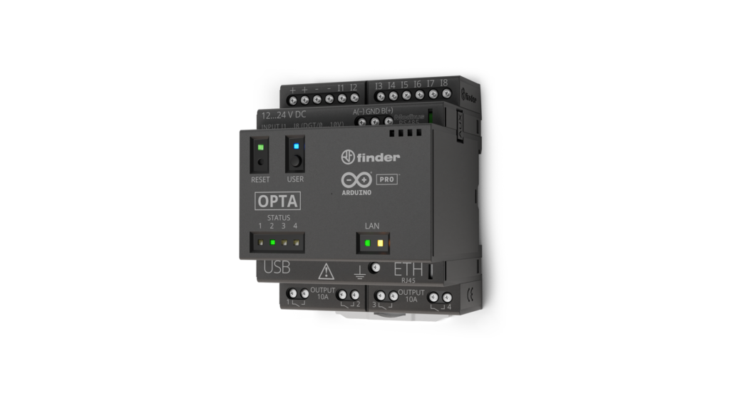
Arduino OPTA plc
Overview
To showcase how easy it is to integrate Edge Impulse with the Arduino Opta PLC, we’ll walk through a practical example using the Arduino DIN Celsius board that comes with the kit, but also a Motor to demonstrate this setup can be used interchangeably. This example demonstrates how to set up a temperature-controlled system, collect data, train a machine learning model, and deploy it for anomaly detection. In this tutorial, you will:- Collect temperature data from a sensor connected to the Opta PLC.
- Train a machine learning model in Edge Impulse to detect anomalies in the data.
- Deploy the model to the Opta PLC for real-time inference.
- Optionally, integrate the model with Arduino Cloud for remote monitoring and visualization.
Webinar: Integrating Edge Impulse with Arduino Opta PLC and Blues Wireless
We ran a webinar on integrating Edge Impulse with Arduino Opta PLC and Blues Wireless for remote monitoring and anomaly detection. The webinar covered the following topics:
- Arduino Opta PLC: Learn about the flexibility and ease of integration of the Arduino Opta micro PLC, designed for industrial environments.
- Edge Impulse for Machine Learning: Understand how to train and implement ML models for anomaly detection on industrial data directly on your Opta PLC.
- Blues for Wireless Connectivity: Explore how Blues’ Wireless for PLC Expansion enables secure cellular connectivity, allowing your Opta PLC to communicate with cloud-based monitoring systems.
Prerequisites
Hardware
- Arduino Opta PLC (Wi-Fi version recommended)
- Opta PLC Starter Kit
Software
- Arduino IDE 2 (Download here)
- Edge Impulse account (Sign up here)
- Edge Impulse CLI (Installation guide)
Step 1: Set Up Your Hardware
Hardware Setup
About the DIN Celsius Board

DIN Celsius
Connecting the DIN Celsius to the Opta PLC
Safety First: Before making any connections, ensure that all power sources are disconnected to prevent electric shock or short circuits. Connections Overview: Power Connections:- Connect the +24V and GND terminals of the DIN Celsius to the corresponding power supply pins.
- Connect Relay 3 (pin 2) on the Opta PLC to Input Heat 1 on the DIN Celsius.
- Connect Relay 4 (pin 3) on the Opta PLC to Input Heat 2 on the DIN Celsius.
- These connections will control the two independent heaters on the DIN Celsius.
- Connect the Output Voltage from the DIN Celsius to the I8 input (analog pin A7) on the Opta PLC.
- This connection allows the PLC to read the temperature sensor data.
- HEAT_LEFT (Relay 3) connected to pin 2
- HEAT_RIGHT (Relay 4) connected to pin 3
- TEMP_SENS connected to analog pin A7
- BTN (User Button) on the Opta PLC
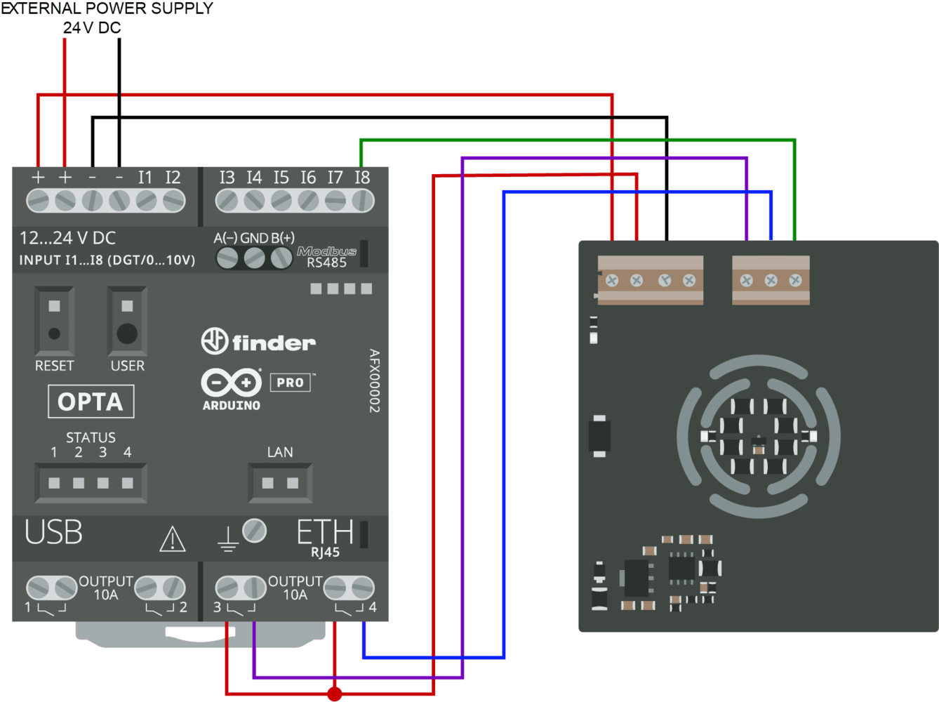
Wiring Diagram
Step 2: Set Up Your Software
Arduino IDE Configuration
Install Necessary Libraries:- Ensure you have the latest Arduino IDE 2 installed.
- Install any required libraries via the Library Manager, such as Edge Impulse SDK and Arduino_HTS221 if using temperature/humidity sensors.
Testing the Connections
Heater Control Test Code:- Upload the Code: Use the Arduino IDE to upload the sketch to the Opta PLC.
- Verify Operation: The LEDs on the DIN Celsius should blink, indicating the heaters are being activated.
- Open Serial Monitor: Set the baud rate to 9600.
- Observe Readings: You should see numerical values corresponding to the temperature sensor output.
Step 3: Collecting Data with Edge Impulse
Create a New Project
- Log In: Access your Edge Impulse account.
- New Project: Create a project named, for example, “Opta PLC Anomaly Detection.”
Data Forwarding Sketch
Upload a sketch to the Opta PLC that reads the temperature sensor and sends data to Edge Impulse. Steps:- Upload the Data Forwarder Sketch: Use the Arduino IDE to upload the sketch to the Opta PLC.
- Run Data Forwarder: In your terminal, execute the data forwarding command.
- Select Serial Port: Choose the serial port corresponding to the Opta PLC.
- Label the Data: As you collect data, assign labels to your data (e.g., “normal,” “anomalous”) based on the system’s behavior.
Note: If you are new to Edge Impulse, please refer to our CLI Data Forwarder documentation for detailed instructions.
Toggle to expand - Data Forwarder Sketch
Toggle to expand - Data Forwarder Sketch
Data Forwarder Sketch:
- Run Data Forwarder: In your terminal, execute:
- Select Serial Port: Choose the serial port corresponding to the Opta PLC.
- Label the Data: Assign labels to your data (e.g., “normal,” “anomalous”) as you collect it.
Step 4: Training the Machine Learning Model
Create an Impulse
Add Blocks: 2. Add Blocks:- Processing Block: Select a Time Series or Spectral Analysis block based on your data characteristics.
- Learning Block: Choose Anomaly Detection using the Gaussian Mixture Model (GMM).
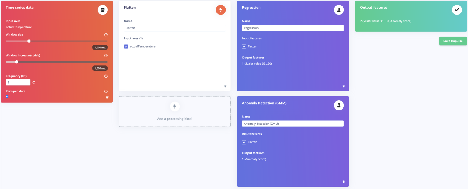
Impulse Studio
Configure the Impulse
- Window Size: Set according to the data frequency (e.g., 1000 ms).
- Window Increase: Set overlap (e.g., 500 ms).
Generate Features
- Compute Features: Navigate to the Generate Features tab and run feature generation.
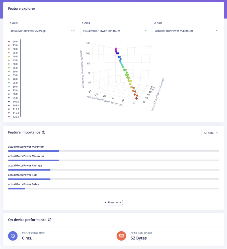
Generate Features
Train the Model
Training Parameters:- Epochs: Start with 100 and adjust as needed.
- Learning Rate: Default of 0.005 is usually sufficient. Start Training: Monitor the accuracy and loss graphs.
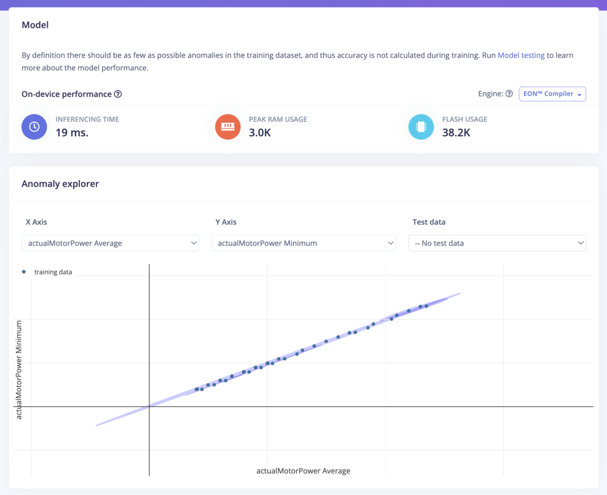
Training Model
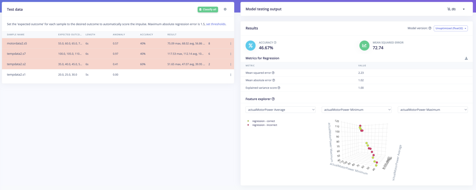
Validate the Model
- Model Testing: Use a separate dataset to evaluate model performance.
- Adjust if Necessary: Retrain or adjust parameters based on results.
Model Validation
Step 5: Deploying the Model to the Opta PLC
Download the Arduino Library
- Deployment Tab: In Edge Impulse, go to Deployment.
- Select Arduino Library: Download the library tailored for your model.
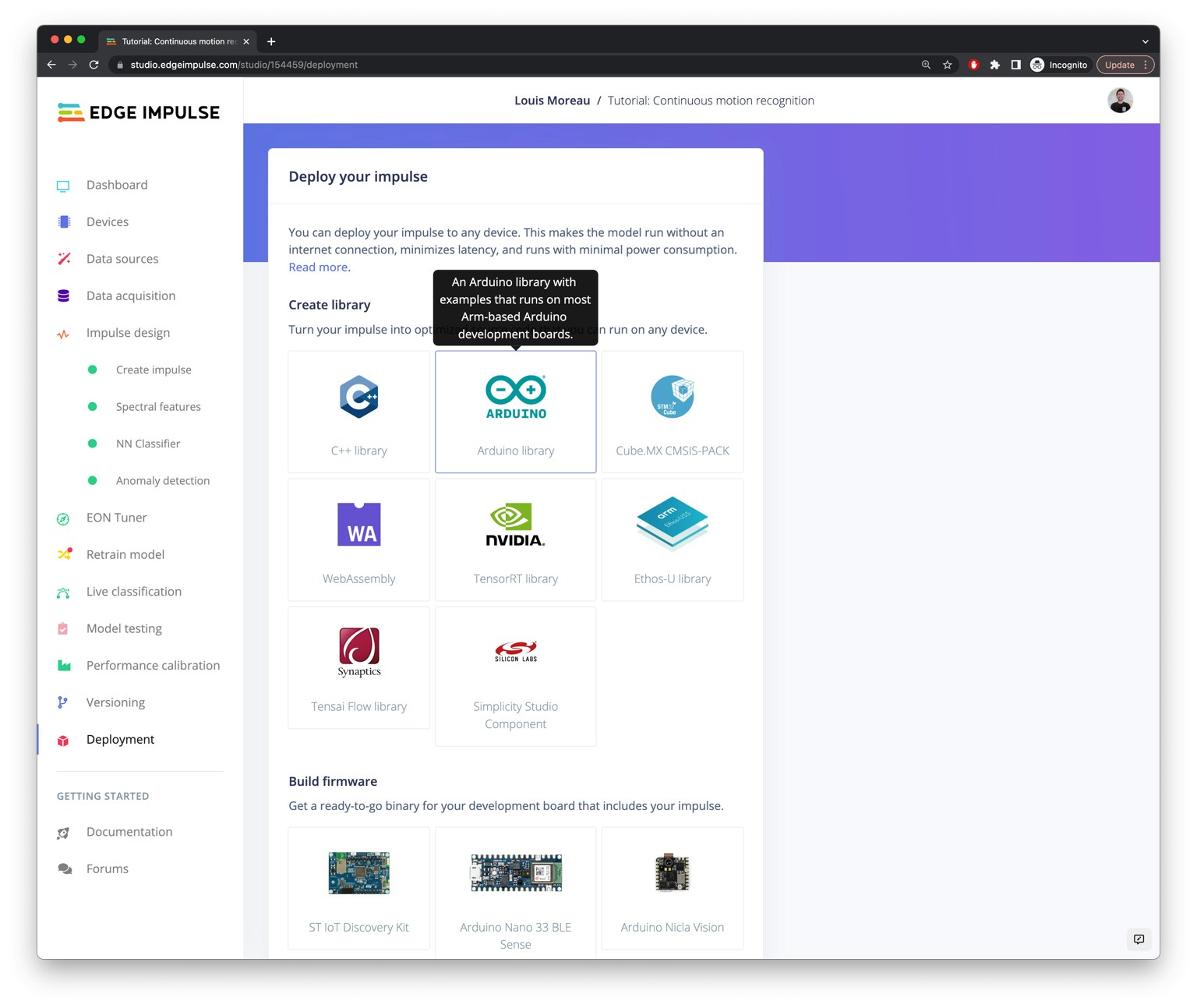
Download Library
Include the Library in Your Sketch
- Add Library to IDE: Import the downloaded library into your Arduino IDE.
Add the Inference Code
If you are new to Arduino inference code, see our Arduino inference code documentation here for more information.Toggle to expand - Inference Code Example
Toggle to expand - Inference Code Example
Inference Code Example:
- Replace
Your_Edge_Impulse_Inference_Library.hwith the actual header file name from your downloaded library. - Set
ANOMALY_THRESHOLDto an appropriate value based on your model’s performance.
Upload the Sketch
- Compile and Upload: Use the Arduino IDE to program the Opta PLC with your new inference code.
- Monitor Output: Open the Serial Monitor to observe inference results and system behavior.
Step 6: Viewing Data on Arduino Cloud via Blues Wireless (Optional)
This section demonstrates integrating Blues Wireless for remote connectivity and monitoring. By connecting your Opta PLC to the cloud, you can visualize data, receive alerts, and monitor system performance from anywhere.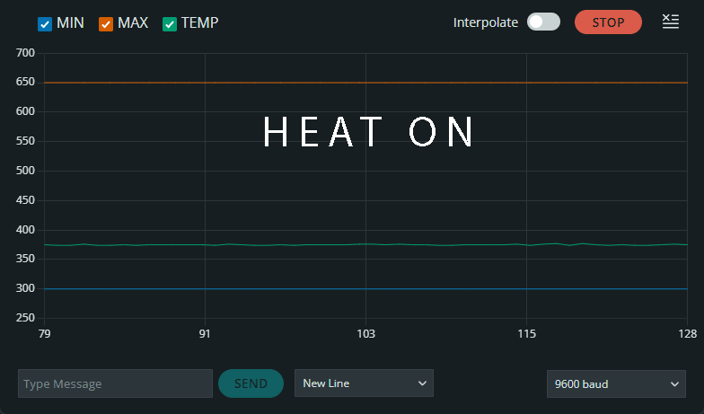
Arduino Cloud
Blues for Wireless Connectivity:
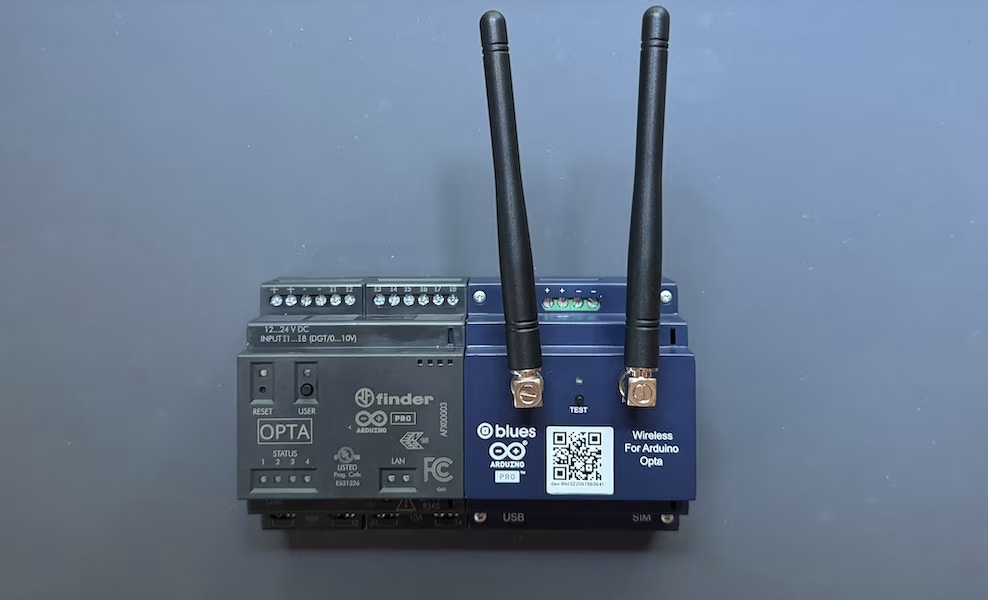
Blues Wireless
This section will be updated following the Blues Wireless Webinar on the 30th of October Sign up here
Step 7: Integration with Ladder Logic (Optional)
In this section, we will integrate the anomaly detection model deployed on the Arduino Opta PLC with a ladder logic program. This integration will allow the machine learning inferences to interact with the PLC’s native ladder logic control system, providing intelligent control responses to anomalies in temperature or motor power.Overview of Ladder Logic Integration
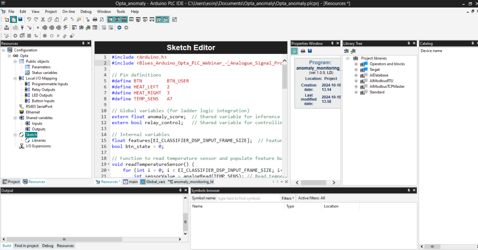
The Arduino PLC IDE allows you to combine an Arduino sketch with ladder logic using Shared Variables. These shared variables act as a bridge between the Edge Impulse inference running on the PLC and the PLC’s control logic written in Ladder Diagram (LD) or other IEC-61131-3 programming languages (such as Function Block Diagram or Structured Text). This enables real-time decision-making based on the machine learning model’s output.Steps for Integration
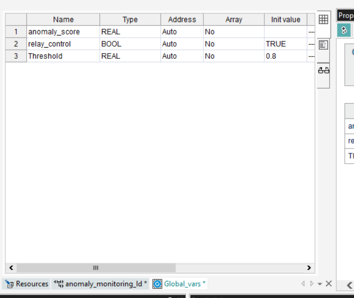
Create Shared Variables
In the Arduino PLC IDE, navigate to theGlobal_vars section to create shared variables that will store the results from the Edge Impulse inference. Define a shared variable for the anomaly score or classification output of the model.
Example:
Shared variable for storing inference result (e.g., float anomaly_score).
Modify Inference Sketch
Update the Edge Impulse inference sketch to store the inference result in the shared variable. This will allow the ladder logic to access the result. Example:Ladder Logic Program
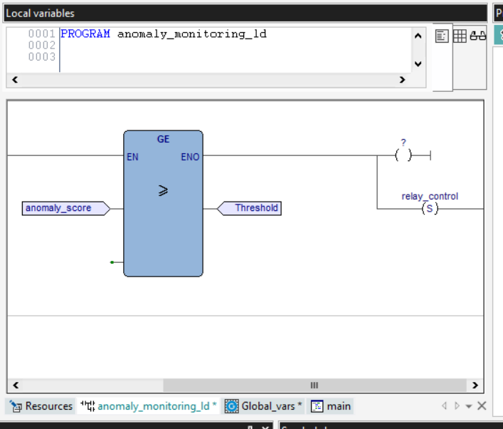
In the PLC IDE, create a new ladder logic program that will read theanomaly_score shared variable. The logic can then trigger actions based on the value, such as activating relays, generating alarms, or shutting down equipment in response to detected anomalies.
Example Ladder Logic:
Create a rung that monitors the anomaly_score. If the score exceeds a certain threshold, the logic can trigger an alarm (e.g., turn on an LED or activate a relay).
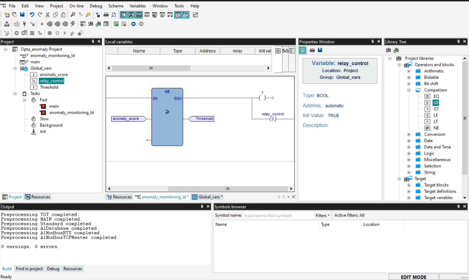
Ladder Logic - Anomaly integration
- Define Inputs (e.g., sensor values, inference results from the Arduino sketch) and Outputs (e.g., control signals like turning on a relay).
- Click Add in the “Shared Inputs” and “Shared Outputs” sections to create global variables. These variables will allow communication between your inference sketch and ladder logic.
Shared Variables
- Inputs: Define variables that will receive values from the Arduino sketch (e.g., anomaly_score).
- Outputs: Define variables that will control actuators (e.g., relay_control).
Step 2: Accessing the Ladder Logic Editor
Create a New Ladder Logic Program:- Go to the Project tab (top-left section).
- Right-click on Programs and select New Program.
- Name the program (e.g., AnomalyDetection_LD) and select Ladder Diagram (LD) as the language.
- Once the program is created, double-click it to open the Ladder Diagram editor. You will see a canvas where you can start adding blocks.
Step 3: Designing the Ladder Logic
Ladder Logic Editor
- On the right panel under the Library Tree, you can see various block types, such as Comparison, Logic, and Arithmetic.
- Comparison blocks will allow you to compare the input (e.g., anomaly_score) to a threshold (e.g., >=).
- Input Condition: Drag a Comparison block (e.g., >=) to compare the anomaly_score to a threshold (e.g., 0.8).
- Output Control: Connect the result of the comparison to an Output coil that controls the relay (e.g., relay_control).
- Input: Select anomaly_score as the input to the comparison block.
- Condition: Set the threshold (e.g., >= 0.8).
- Output: Set the output to control a relay (e.g., activate relay_control when the condition is met).
Assigning the Ladder Logic to a Task
In the PLC IDE, assign the Arduino sketch (which runs the inference) to a task such as Fast (runs every 10ms) or Background (runs every 500ms) based on your system’s real-time requirements. Attach the ladder logic program to the same or another appropriate task to ensure it reacts to the updated shared variables in a timely manner. Steps:- Go to the Project tab and locate the Tasks section.
- Assign the ladder logic program (e.g., AnomalyDetection_LD) to an appropriate task (e.g., Fast Task for real-time control).
Ladder Logic - Sketch Integration
Monitor and Debug
Use the Watch window in the PLC IDE to monitor the shared variables and ensure the system responds correctly to anomalies detected by the machine learning model. Upload the Arduino Sketch:- Ensure your Arduino sketch is uploaded to the Opta PLC to provide the inference results.
- Start the ladder logic program from the Arduino PLC IDE.
- Monitor the shared variables using the Watch window to see how the ladder logic reacts to the inference results.
Benefits of Ladder Logic Integration
- Real-time Control: By integrating anomaly detection with ladder logic, you can implement real-time, intelligent control systems that take action based on data-driven decisions from the Edge Impulse model.
- Easy Troubleshooting: Using ladder logic alongside machine learning allows for clear, visual representation of control logic, making it easier to debug and monitor the system’s responses to anomalies.
- Seamless PLC Integration: The Arduino PLC IDE provides a smooth environment for combining traditional control logic with modern machine learning, ensuring compatibility and ease of use.
Conclusion
Congratulations! You have successfully implemented anomaly detection on an Arduino Opta PLC using Edge Impulse. This tutorial demonstrates the seamless integration of machine learning models with industrial automation systems, enabling real-time monitoring and fault detection. Please share your experiences and feedback with us on the Edge Impulse forum. For more information on Edge Impulse and Arduino Opta PLC, visit the official websites:- Arduino Opta PLC
- Arduino Cloud Issues: We are aware of issues with Arduino Cloud .properties file format vs IDE and are working with Arduino. If you have issues try moving the .properties file to the same folder as the .ino file and re-uploading the sketch.