LogoLogo
HomeAPI & SDKsProjectsForumStudio
  • Getting started
    • For beginners
    • For ML practitioners
    • For embedded engineers
  • Frequently asked questions (FAQ)
  • Tutorials
    • End-to-end tutorials
      • Computer vision
        • Image classification
        • Object detection
          • Object detection with bounding boxes
          • Detect objects with centroid (FOMO)
        • Visual anomaly detection
        • Visual regression
      • Audio
        • Sound recognition
        • Keyword spotting
      • Time-series
        • Motion recognition + anomaly detection
        • Regression + anomaly detection
        • HR/HRV
        • Environmental (Sensor fusion)
    • Data
      • Data ingestion
        • Collecting image data from the Studio
        • Collecting image data with your mobile phone
        • Collecting image data with the OpenMV Cam H7 Plus
        • Using the Edge Impulse Python SDK to upload and download data
        • Trigger connected board data sampling
        • Ingest multi-labeled data using the API
      • Synthetic data
        • Generate audio datasets using Eleven Labs
        • Generate image datasets using Dall-E
        • Generate keyword spotting datasets using Google TTS
        • Generate physics simulation datasets using PyBullet
        • Generate timeseries data with MATLAB
      • Labeling
        • Label audio data using your existing models
        • Label image data using GPT-4o
      • Edge Impulse Datasets
    • Feature extraction
      • Building custom processing blocks
      • Sensor fusion using embeddings
    • Machine learning
      • Classification with multiple 2D input features
      • Visualize neural networks decisions with Grad-CAM
      • Sensor fusion using embeddings
      • FOMO self-attention
    • Inferencing & post-processing
      • Count objects using FOMO
      • Continuous audio sampling
      • Multi-impulse (C++)
      • Multi-impulse (Python)
    • Lifecycle management
      • CI/CD with GitHub Actions
      • Data aquisition from S3 object store - Golioth on AI
      • OTA model updates
        • with Arduino IDE (for ESP32)
        • with Arduino IoT Cloud
        • with Blues Wireless
        • with Docker on Allxon
        • with Docker on Balena
        • with Docker on NVIDIA Jetson
        • with Espressif IDF
        • with Nordic Thingy53 and the Edge Impulse app
        • with Particle Workbench
        • with Zephyr on Golioth
    • API examples
      • Customize the EON Tuner
      • Ingest multi-labeled data using the API
      • Python API bindings example
      • Running jobs using the API
      • Trigger connected board data sampling
    • Python SDK examples
      • Using the Edge Impulse Python SDK to run EON Tuner
      • Using the Edge Impulse Python SDK to upload and download data
      • Using the Edge Impulse Python SDK with Hugging Face
      • Using the Edge Impulse Python SDK with SageMaker Studio
      • Using the Edge Impulse Python SDK with TensorFlow and Keras
      • Using the Edge Impulse Python SDK with Weights & Biases
    • Expert network projects
  • Edge Impulse Studio
    • Organization hub
      • Users
      • Data campaigns
      • Data
        • Cloud data storage
      • Data pipelines
      • Data transformation
        • Transformation blocks
      • Upload portals
      • Custom blocks
        • Custom AI labeling blocks
        • Custom deployment blocks
        • Custom learning blocks
        • Custom processing blocks
        • Custom synthetic data blocks
        • Custom transformation blocks
      • Health reference design
        • Synchronizing clinical data with a bucket
        • Validating clinical data
        • Querying clinical data
        • Transforming clinical data
    • Project dashboard
      • Select AI hardware
    • Devices
    • Data acquisition
      • Uploader
      • Data explorer
      • Data sources
      • Synthetic data
      • Labeling queue
      • AI labeling
      • CSV Wizard (time-series)
      • Multi-label (time-series)
      • Tabular data (pre-processed & non-time-series)
      • Metadata
      • Auto-labeler | deprecated
    • Impulses
    • EON Tuner
      • Search space
    • Processing blocks
      • Audio MFCC
      • Audio MFE
      • Audio Syntiant
      • Flatten
      • HR/HRV features
      • Image
      • IMU Syntiant
      • Raw data
      • Spectral features
      • Spectrogram
      • Custom processing blocks
      • Feature explorer
    • Learning blocks
      • Anomaly detection (GMM)
      • Anomaly detection (K-means)
      • Classification
      • Classical ML
      • Object detection
        • MobileNetV2 SSD FPN
        • FOMO: Object detection for constrained devices
      • Object tracking
      • Regression
      • Transfer learning (images)
      • Transfer learning (keyword spotting)
      • Visual anomaly detection (FOMO-AD)
      • Custom learning blocks
      • Expert mode
      • NVIDIA TAO | deprecated
    • Retrain model
    • Live classification
    • Model testing
    • Performance calibration
    • Deployment
      • EON Compiler
      • Custom deployment blocks
    • Versioning
    • Bring your own model (BYOM)
    • File specifications
      • deployment-metadata.json
      • ei-metadata.json
      • ids.json
      • parameters.json
      • sample_id_details.json
      • train_input.json
  • Tools
    • API and SDK references
    • Edge Impulse CLI
      • Installation
      • Serial daemon
      • Uploader
      • Data forwarder
      • Impulse runner
      • Blocks
      • Himax flash tool
    • Edge Impulse for Linux
      • Linux Node.js SDK
      • Linux Go SDK
      • Linux C++ SDK
      • Linux Python SDK
      • Flex delegates
      • Rust Library
    • Rust Library
    • Edge Impulse Python SDK
  • Run inference
    • C++ library
      • As a generic C++ library
      • On Android
      • On your desktop computer
      • On your Alif Ensemble Series Device
      • On your Espressif ESP-EYE (ESP32) development board
      • On your Himax WE-I Plus
      • On your Raspberry Pi Pico (RP2040) development board
      • On your SiLabs Thunderboard Sense 2
      • On your Spresense by Sony development board
      • On your Syntiant TinyML Board
      • On your TI LaunchPad using GCC and the SimpleLink SDK
      • On your Zephyr-based Nordic Semiconductor development board
    • Arm Keil MDK CMSIS-PACK
    • Arduino library
      • Arduino IDE 1.18
    • Cube.MX CMSIS-PACK
    • Docker container
    • DRP-AI library
      • DRP-AI on your Renesas development board
      • DRP-AI TVM i8 on Renesas RZ/V2H
    • IAR library
    • Linux EIM executable
    • OpenMV
    • Particle library
    • Qualcomm IM SDK GStreamer
    • WebAssembly
      • Through WebAssembly (Node.js)
      • Through WebAssembly (browser)
    • Edge Impulse firmwares
    • Hardware specific tutorials
      • Image classification - Sony Spresense
      • Audio event detection with Particle boards
      • Motion recognition - Particle - Photon 2 & Boron
      • Motion recognition - RASynBoard
      • Motion recognition - Syntiant
      • Object detection - SiLabs xG24 Dev Kit
      • Sound recognition - TI LaunchXL
      • Keyword spotting - TI LaunchXL
      • Keyword spotting - Syntiant - RC Commands
      • Running NVIDIA TAO models on the Renesas RA8D1
      • Two cameras, two models - running multiple object detection models on the RZ/V2L
  • Edge AI Hardware
    • Overview
    • Production-ready
      • Advantech ICAM-540
      • Seeed SenseCAP A1101
      • Industry reference design - BrickML
    • MCU
      • Ambiq Apollo4 family of SoCs
      • Ambiq Apollo510
      • Arducam Pico4ML TinyML Dev Kit
      • Arduino Nano 33 BLE Sense
      • Arduino Nicla Sense ME
      • Arduino Nicla Vision
      • Arduino Portenta H7
      • Blues Wireless Swan
      • Espressif ESP-EYE
      • Himax WE-I Plus
      • Infineon CY8CKIT-062-BLE Pioneer Kit
      • Infineon CY8CKIT-062S2 Pioneer Kit
      • Nordic Semi nRF52840 DK
      • Nordic Semi nRF5340 DK
      • Nordic Semi nRF9160 DK
      • Nordic Semi nRF9161 DK
      • Nordic Semi nRF9151 DK
      • Nordic Semi nRF7002 DK
      • Nordic Semi Thingy:53
      • Nordic Semi Thingy:91
      • Open MV Cam H7 Plus
      • Particle Photon 2
      • Particle Boron
      • RAKwireless WisBlock
      • Raspberry Pi RP2040
      • Renesas CK-RA6M5 Cloud Kit
      • Renesas EK-RA8D1
      • Seeed Wio Terminal
      • Seeed XIAO nRF52840 Sense
      • Seeed XIAO ESP32 S3 Sense
      • SiLabs Thunderboard Sense 2
      • Sony's Spresense
      • ST B-L475E-IOT01A
      • TI CC1352P Launchpad
    • MCU + AI accelerators
      • Alif Ensemble
      • Arduino Nicla Voice
      • Avnet RASynBoard
      • Seeed Grove - Vision AI Module
      • Seeed Grove Vision AI Module V2 (WiseEye2)
      • Himax WiseEye2 Module and ISM Devboard
      • SiLabs xG24 Dev Kit
      • STMicroelectronics STM32N6570-DK
      • Synaptics Katana EVK
      • Syntiant Tiny ML Board
    • CPU
      • macOS
      • Linux x86_64
      • Raspberry Pi 4
      • Raspberry Pi 5
      • Texas Instruments SK-AM62
      • Microchip SAMA7G54
      • Renesas RZ/G2L
    • CPU + AI accelerators
      • AVNET RZBoard V2L
      • BrainChip AKD1000
      • i.MX 8M Plus EVK
      • Digi ConnectCore 93 Development Kit
      • MemryX MX3
      • MistyWest MistySOM RZ/V2L
      • Qualcomm Dragonwing RB3 Gen 2 Dev Kit
      • Renesas RZ/V2L
      • Renesas RZ/V2H
      • IMDT RZ/V2H
      • Texas Instruments SK-TDA4VM
      • Texas Instruments SK-AM62A-LP
      • Texas Instruments SK-AM68A
      • Thundercomm Rubik Pi 3
    • GPU
      • Advantech ICAM-540
      • NVIDIA Jetson
      • Seeed reComputer Jetson
    • Mobile phone
    • Porting guide
  • Integrations
    • Arduino Machine Learning Tools
    • AWS IoT Greengrass
    • Embedded IDEs - Open-CMSIS
    • NVIDIA Omniverse
    • Scailable
    • Weights & Biases
  • Tips & Tricks
    • Combining impulses
    • Increasing model performance
    • Optimizing compute time
    • Inference performance metrics
  • Concepts
    • Glossary
    • Course: Edge AI Fundamentals
      • Introduction to edge AI
      • What is edge computing?
      • What is machine learning (ML)?
      • What is edge AI?
      • How to choose an edge AI device
      • Edge AI lifecycle
      • What is edge MLOps?
      • What is Edge Impulse?
      • Case study: Izoelektro smart grid monitoring
      • Test and certification
    • Data engineering
      • Audio feature extraction
      • Motion feature extraction
    • Machine learning
      • Data augmentation
      • Evaluation metrics
      • Neural networks
        • Layers
        • Activation functions
        • Loss functions
        • Optimizers
          • Learned optimizer (VeLO)
        • Epochs
    • What is embedded ML, anyway?
    • What is edge machine learning (edge ML)?
Powered by GitBook
On this page
  • Overview
  • Prerequisites
  • Step 1: Set Up Your Hardware
  • Step 2: Set Up Your Software
  • Step 3: Collecting Data with Edge Impulse
  • Step 4: Training the Machine Learning Model
  • Step 5: Deploying the Model to the Opta PLC
  • Step 6: Viewing Data on Arduino Cloud via Blues Wireless (Optional)
  • Step 7: Integration with Ladder Logic (Optional)
  • Conclusion
  • Troubleshooting

Was this helpful?

Export as PDF
  1. Tutorials
  2. End-to-end tutorials
  3. Time-series

Regression + anomaly detection

PreviousMotion recognition + anomaly detectionNextHR/HRV

Last updated 3 months ago

Was this helpful?

This tutorial demonstrates how to implement and integrate anomaly detection on an Arduino Opta PLC using Edge Impulse. Anomaly detection is a machine learning technique that identifies unusual patterns in data, making it ideal for monitoring industrial processes and equipment. By training a model to recognize normal behavior, you can detect deviations that may indicate faults or malfunctions.

Overview

To showcase how easy it is to integrate Edge Impulse with the Arduino Opta PLC, we'll walk through a practical example using the Arduino DIN Celsius board that comes with the kit, but also a Motor to demonstrate this setup can be used interchangeably. This example demonstrates how to set up a temperature-controlled system, collect data, train a machine learning model, and deploy it for anomaly detection.

In this tutorial, you will:

  • Collect temperature data from a sensor connected to the Opta PLC.

  • Train a machine learning model in Edge Impulse to detect anomalies in the data.

  • Deploy the model to the Opta PLC for real-time inference.

  • Optionally, integrate the model with Arduino Cloud for remote monitoring and visualization.

Webinar: Integrating Edge Impulse with Arduino Opta PLC and Blues Wireless

We ran a webinar on integrating Edge Impulse with Arduino Opta PLC and Blues Wireless for remote monitoring and anomaly detection. The webinar covered the following topics:

  • Arduino Opta PLC: Learn about the flexibility and ease of integration of the Arduino Opta micro PLC, designed for industrial environments.

  • Edge Impulse for Machine Learning: Understand how to train and implement ML models for anomaly detection on industrial data directly on your Opta PLC.

  • Blues for Wireless Connectivity: Explore how Blues' Wireless for PLC Expansion enables secure cellular connectivity, allowing your Opta PLC to communicate with cloud-based monitoring systems.

The webinar is now available on-demand here.

Prerequisites

Hardware

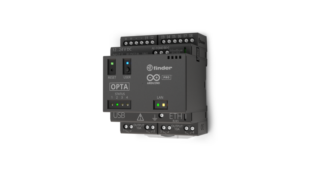
  • Arduino Opta PLC (Wi-Fi version recommended)

  • Opta PLC Starter Kit

Software

  • Arduino IDE 2 (Download here)

  • Edge Impulse account (Sign up here)

  • Edge Impulse CLI (Installation guide

Step 1: Set Up Your Hardware

Hardware Setup

About the DIN Celsius Board
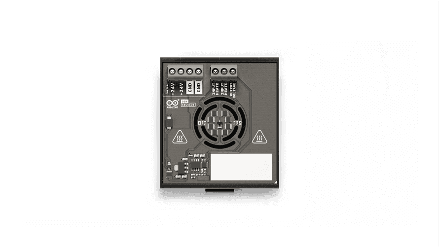
The DIN Celsius is an all-in-one temperature laboratory offering two independent heaters and a temperature sensor. It allows you to simulate heating scenarios and monitor temperature changes, making it ideal for testing our anomaly detection use case, we can introduce an anomaly by turning off one of the heaters to cause a deviation from the normal condition.

Connecting the DIN Celsius to the Opta PLC

Safety First: Before making any connections, ensure that all power sources are disconnected to prevent electric shock or short circuits.

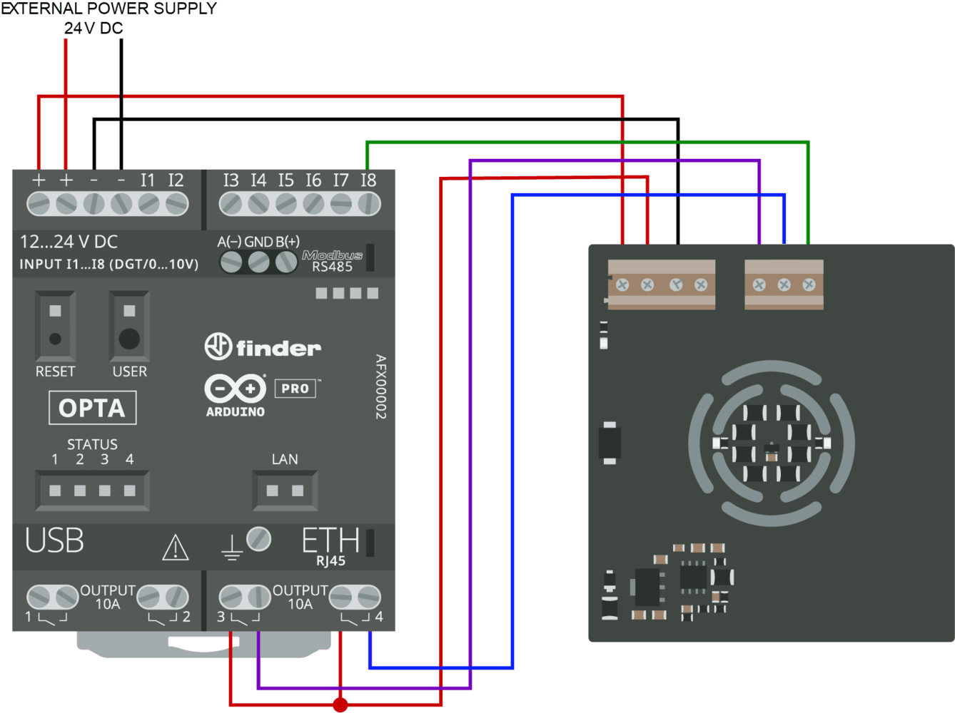
Connections Overview:

Power Connections:

  • Connect the +24V and GND terminals of the DIN Celsius to the corresponding power supply pins.

Heater Control:

  • Connect Relay 3 (pin 2) on the Opta PLC to Input Heat 1 on the DIN Celsius.

  • Connect Relay 4 (pin 3) on the Opta PLC to Input Heat 2 on the DIN Celsius.

  • These connections will control the two independent heaters on the DIN Celsius.

Temperature Sensor Input:

  • Connect the Output Voltage from the DIN Celsius to the I8 input (analog pin A7) on the Opta PLC.

  • This connection allows the PLC to read the temperature sensor data.

Pin Definitions:

  • HEAT_LEFT (Relay 3) connected to pin 2

  • HEAT_RIGHT (Relay 4) connected to pin 3

  • TEMP_SENS connected to analog pin A7

  • BTN (User Button) on the Opta PLC

Step 2: Set Up Your Software

Arduino IDE Configuration

Install Necessary Libraries:

  • Ensure you have the latest Arduino IDE 2 installed.

  • Install any required libraries via the Library Manager, such as Edge Impulse SDK and Arduino_HTS221 if using temperature/humidity sensors.

Define Pin Constants:

#define BTN         BTN_USER       // User button on Opta WiFi
#define HEAT_LEFT   2              // Left heater control pin
#define HEAT_RIGHT  3              // Right heater control pin
#define TEMP_SENS   A7             // Temperature sensor analog pin

Testing the Connections

Heater Control Test Code:

void setup() {
  pinMode(HEAT_LEFT, OUTPUT);
  pinMode(HEAT_RIGHT, OUTPUT);
}

void loop() {
  digitalWrite(HEAT_LEFT, HIGH);
  digitalWrite(HEAT_RIGHT, HIGH);
  delay(1000);
  digitalWrite(HEAT_LEFT, LOW);
  digitalWrite(HEAT_RIGHT, LOW);
  delay(1000);
}
  • Upload the Code: Use the Arduino IDE to upload the sketch to the Opta PLC.

  • Verify Operation: The LEDs on the DIN Celsius should blink, indicating the heaters are being activated.

Temperature Sensor Reading Test:

void setup() {
  Serial.begin(9600);
  pinMode(TEMP_SENS, INPUT);
}

void loop() {
  int sensorValue = analogRead(TEMP_SENS);
  Serial.println(sensorValue);
  delay(250);
}
  • Open Serial Monitor: Set the baud rate to 9600.

  • Observe Readings: You should see numerical values corresponding to the temperature sensor output.

Step 3: Collecting Data with Edge Impulse

Create a New Project

  • Log In: Access your Edge Impulse account.

  • New Project: Create a project named, for example, "Opta PLC Anomaly Detection."

Data Forwarding Sketch

Upload a sketch to the Opta PLC that reads the temperature sensor and sends data to Edge Impulse.

Steps:

  1. Upload the Data Forwarder Sketch: Use the Arduino IDE to upload the sketch to the Opta PLC.

  2. Run Data Forwarder: In your terminal, execute the data forwarding command.

  3. Select Serial Port: Choose the serial port corresponding to the Opta PLC.

  4. Label the Data: As you collect data, assign labels to your data (e.g., "normal," "anomalous") based on the system's behavior.

Note: If you are new to Edge Impulse, please refer to our CLI Data Forwarder documentation for detailed instructions.

Toggle to expand - Data Forwarder Sketch

Data Forwarder Sketch:

void setup() {
  Serial.begin(115200);
  while (!Serial);

  pinMode(TEMP_SENS, INPUT);
  Serial.println("Edge Impulse Data Forwarder Example");
}

void loop() {
  float temperature = analogRead(TEMP_SENS) * (10.0 / 1024.0); // Convert to voltage
  Serial.print("Temperature: ");
  Serial.println(temperature);

  // Send data in edge-impulse-data-forwarder format
  Serial.print("1,");
  Serial.println(temperature);

  delay(1000);
}
  • Run Data Forwarder: In your terminal, execute:

    edge-impulse-data-forwarder
  • Select Serial Port: Choose the serial port corresponding to the Opta PLC.

  • Label the Data: Assign labels to your data (e.g., "normal," "anomalous") as you collect it.

If you are new to Edge Impulse please see our CLI Data Forwarder documentation.

Step 4: Training the Machine Learning Model

Create an Impulse

Add Blocks: 2. Add Blocks:

  • Processing Block: Select a Time Series or Spectral Analysis block based on your data characteristics.

  • Learning Block: Choose Anomaly Detection using the Gaussian Mixture Model (GMM).
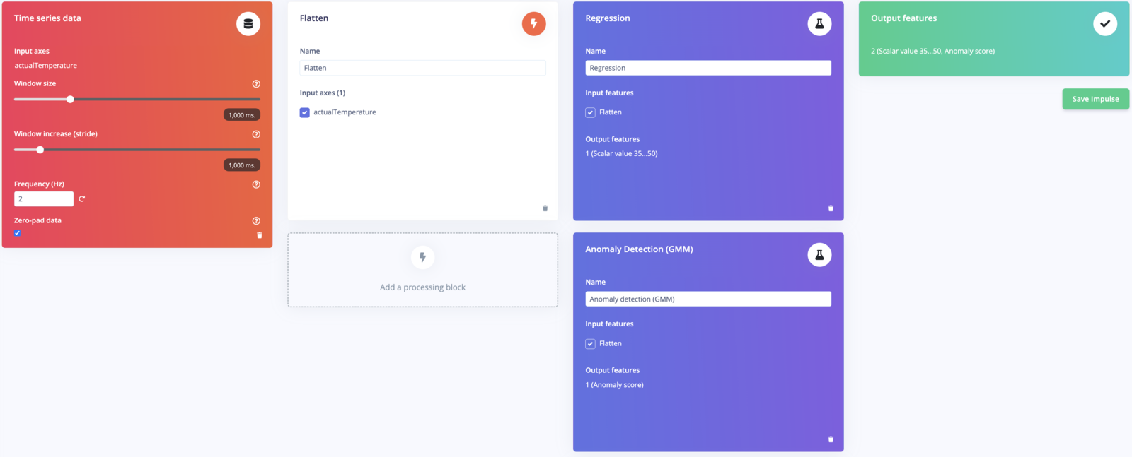
Configure the Impulse

  • Window Size: Set according to the data frequency (e.g., 1000 ms).

  • Window Increase: Set overlap (e.g., 500 ms).

Generate Features

  • Compute Features: Navigate to the Generate Features tab and run feature generation.
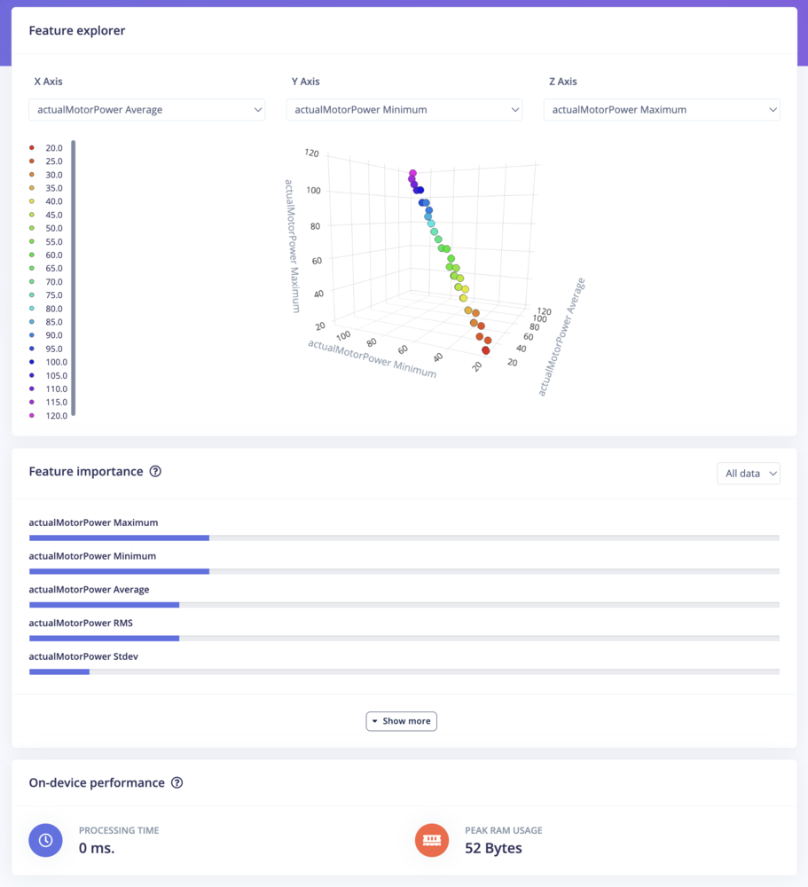
Train the Model

Training Parameters:

  • Epochs: Start with 100 and adjust as needed.

  • Learning Rate: Default of 0.005 is usually sufficient. Start Training: Monitor the accuracy and loss graphs.
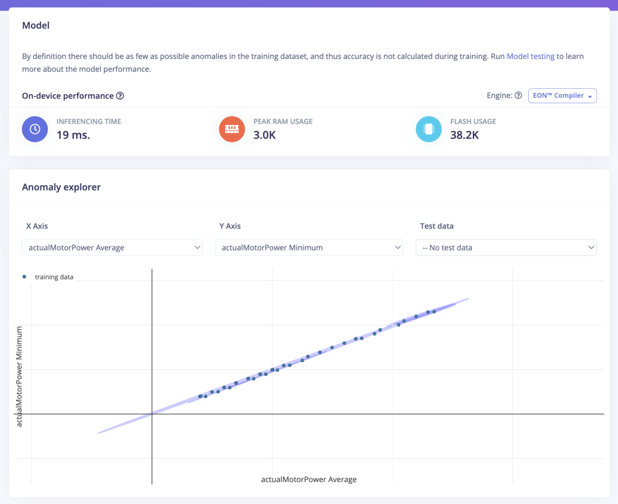
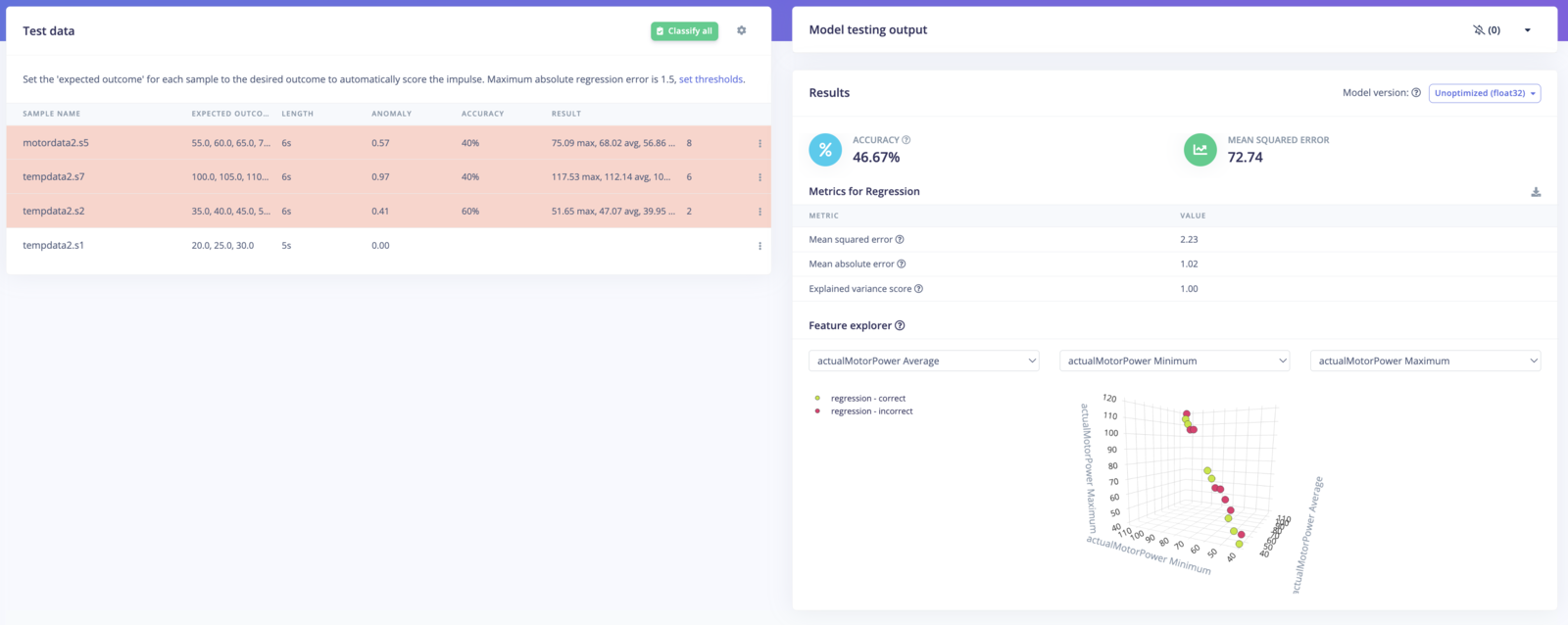
Validate the Model

  • Model Testing: Use a separate dataset to evaluate model performance.

  • Adjust if Necessary: Retrain or adjust parameters based on results.
Step 5: Deploying the Model to the Opta PLC

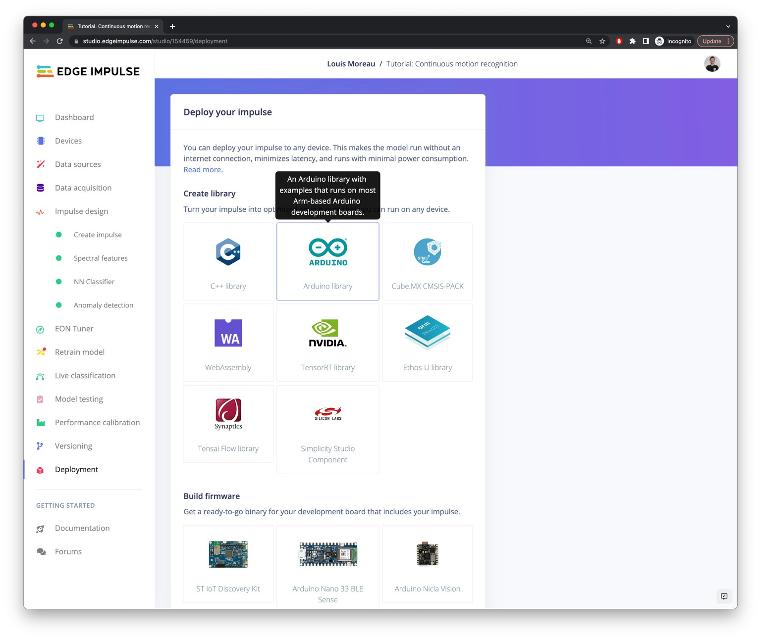
Download the Arduino Library

  • Deployment Tab: In Edge Impulse, go to Deployment.

  • Select Arduino Library: Download the library tailored for your model.
Include the Library in Your Sketch

  • Add Library to IDE: Import the downloaded library into your Arduino IDE.

Add the Inference Code

If you are new to Arduino inference code, see our Arduino inference code documentation here for more information.

Toggle to expand - Inference Code Example

Inference Code Example:

#include <Your_Edge_Impulse_Inference_Library.h>
#include <edge-impulse-sdk/classifier/ei_run_classifier.h>

// Define the feature buffer
float features[EI_CLASSIFIER_DSP_INPUT_FRAME_SIZE];

void setup() {
  Serial.begin(115200);
  while (!Serial);

  pinMode(TEMP_SENS, INPUT);
  Serial.println("Edge Impulse Inference Example");
}

void loop() {
  // Collect data
  for (size_t i = 0; i < EI_CLASSIFIER_DSP_INPUT_FRAME_SIZE; i++) {
    features[i] = analogRead(TEMP_SENS) * (10.0 / 1024.0);
    delay(10); // Adjust delay as needed
  }

  // Prepare signal
  signal_t signal;
  numpy::signal_from_buffer(features, EI_CLASSIFIER_DSP_INPUT_FRAME_SIZE, &signal);

  // Run inference
  ei_impulse_result_t result = { 0 };
  EI_IMPULSE_ERROR res = run_classifier(&signal, &result, false);

  if (res != EI_IMPULSE_OK) {
    Serial.print("ERR: Failed to run classifier (");
    Serial.print(res);
    Serial.println(")");
    return;
  }

  // Print results
  Serial.println("Inference results:");
  for (size_t ix = 0; ix < EI_CLASSIFIER_LABEL_COUNT; ix++) {
    Serial.print(result.classification[ix].label);
    Serial.print(": ");
    Serial.println(result.classification[ix].value);
  }

  // Control heaters based on anomaly detection
  if (result.anomaly > ANOMALY_THRESHOLD) {
    // Anomaly detected, take action
    Serial.println("Anomaly detected!");
    digitalWrite(HEAT_LEFT, LOW);
    digitalWrite(HEAT_RIGHT, LOW);
  } else {
    // Normal operation
    digitalWrite(HEAT_LEFT, HIGH);
    digitalWrite(HEAT_RIGHT, HIGH);
  }

  delay(1000);
}
  • Replace Your_Edge_Impulse_Inference_Library.h with the actual header file name from your downloaded library.

  • Set ANOMALY_THRESHOLD to an appropriate value based on your model's performance.

Upload the Sketch

  • Compile and Upload: Use the Arduino IDE to program the Opta PLC with your new inference code.

  • Monitor Output: Open the Serial Monitor to observe inference results and system behavior.

Step 6: Viewing Data on Arduino Cloud via Blues Wireless (Optional)

This section demonstrates integrating Blues Wireless for remote connectivity and monitoring. By connecting your Opta PLC to the cloud, you can visualize data, receive alerts, and monitor system performance from anywhere.
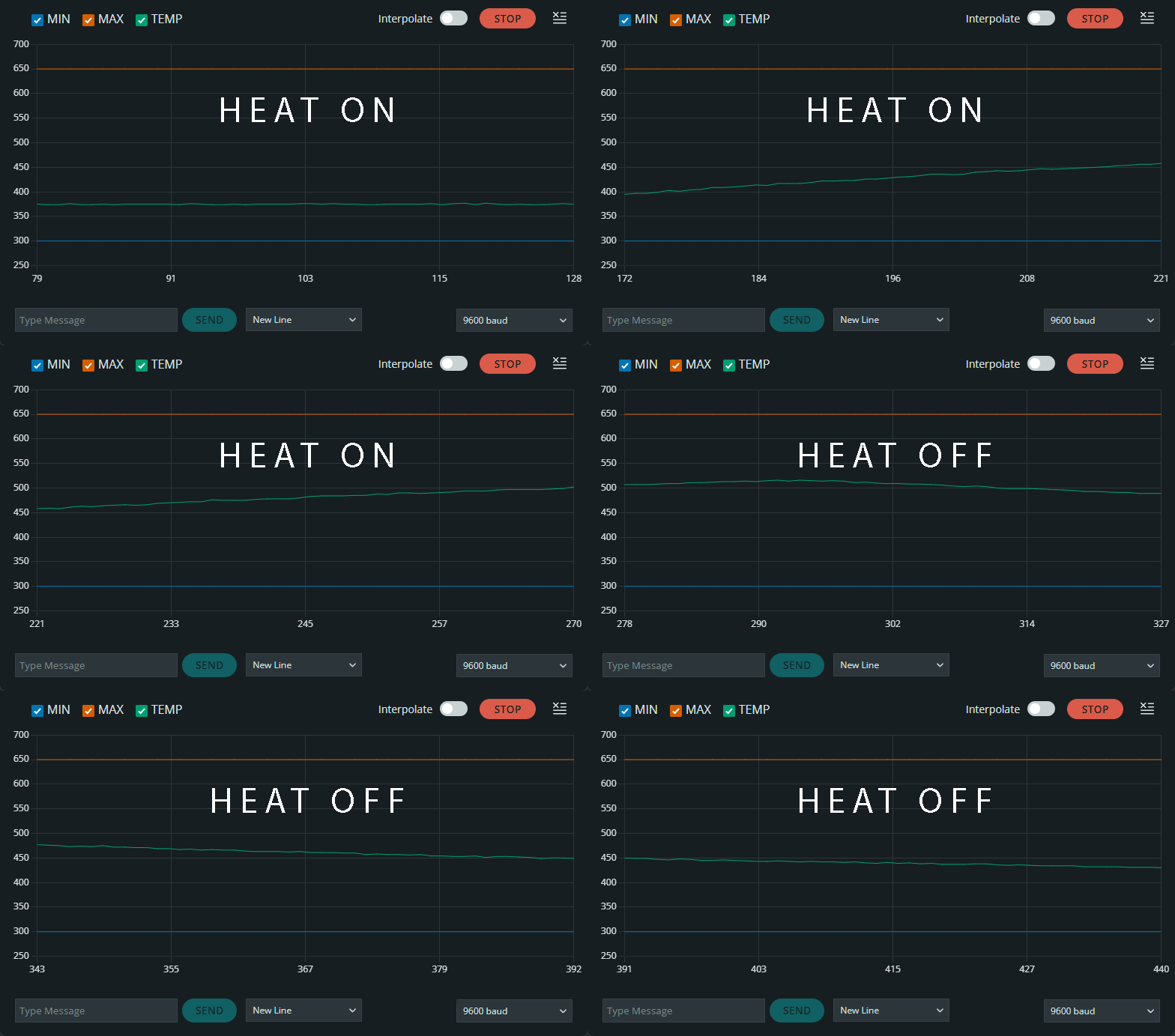
See the full Arduino OPTA for Arduino Cloud guide here.

Blues for Wireless Connectivity:

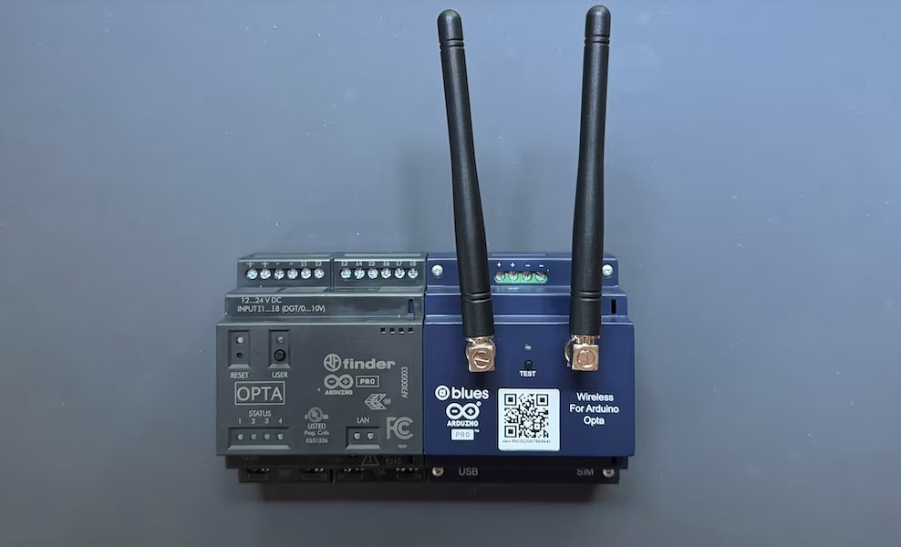
Explore how Blues' Wireless for PLC Expansion enables seamless, secure cellular connectivity, allowing your Opta PLC to communicate with your cloud-based monitoring systems, regardless of location and without the hassle of local Wi-Fi.

See the Blues Wireless here.

This section will be updated following the Blues Wireless Webinar on the 30th of October Sign up here

Step 7: Integration with Ladder Logic (Optional)

In this section, we will integrate the anomaly detection model deployed on the Arduino Opta PLC with a ladder logic program. This integration will allow the machine learning inferences to interact with the PLC's native ladder logic control system, providing intelligent control responses to anomalies in temperature or motor power.

Overview of Ladder Logic Integration

The Arduino PLC IDE allows you to combine an Arduino sketch with ladder logic using Shared Variables. These shared variables act as a bridge between the Edge Impulse inference running on the PLC and the PLC's control logic written in Ladder Diagram (LD) or other IEC-61131-3 programming languages (such as Function Block Diagram or Structured Text). This enables real-time decision-making based on the machine learning model's output.

Steps for Integration

Create Shared Variables

In the Arduino PLC IDE, navigate to the Global_vars section to create shared variables that will store the results from the Edge Impulse inference. Define a shared variable for the anomaly score or classification output of the model.

Example:

Shared variable for storing inference result (e.g., float anomaly_score).

Modify Inference Sketch

Update the Edge Impulse inference sketch to store the inference result in the shared variable. This will allow the ladder logic to access the result.

Example:

float anomaly_score;  // Shared variable to store the inference result

void setup() {
  Serial.begin(115200);
  pinMode(A7, INPUT);  // Sensor input
}

void loop() {
  float sensorValue = analogRead(A7) * (10.0 / 1024.0);  // Read sensor value
  anomaly_score = run_inference(sensorValue);  // Store inference result
  delay(1000);  // Adjust as needed
}

Ladder Logic Program

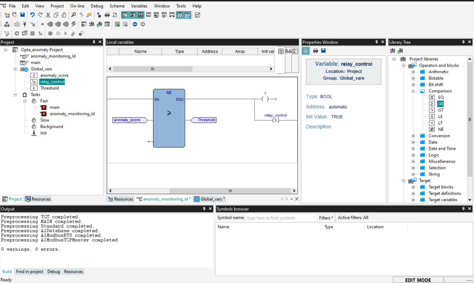
In the PLC IDE, create a new ladder logic program that will read the anomaly_score shared variable. The logic can then trigger actions based on the value, such as activating relays, generating alarms, or shutting down equipment in response to detected anomalies.

Example Ladder Logic:

Create a rung that monitors the anomaly_score. If the score exceeds a certain threshold, the logic can trigger an alarm (e.g., turn on an LED or activate a relay).
Add Inputs and Outputs:

  • Define Inputs (e.g., sensor values, inference results from the Arduino sketch) and Outputs (e.g., control signals like turning on a relay).

  • Click Add in the "Shared Inputs" and "Shared Outputs" sections to create global variables. These variables will allow communication between your inference sketch and ladder logic.
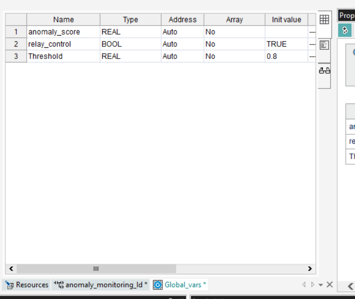
Set up the Inputs/Outputs:

  • Inputs: Define variables that will receive values from the Arduino sketch (e.g., anomaly_score).

  • Outputs: Define variables that will control actuators (e.g., relay_control).

Step 2: Accessing the Ladder Logic Editor

Create a New Ladder Logic Program:

  • Go to the Project tab (top-left section).

  • Right-click on Programs and select New Program.

  • Name the program (e.g., AnomalyDetection_LD) and select Ladder Diagram (LD) as the language.

Opening the Ladder Logic Editor:

  • Once the program is created, double-click it to open the Ladder Diagram editor. You will see a canvas where you can start adding blocks.

Step 3: Designing the Ladder Logic
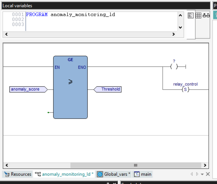
Drag and Drop Components:

  • On the right panel under the Library Tree, you can see various block types, such as Comparison, Logic, and Arithmetic.

  • Comparison blocks will allow you to compare the input (e.g., anomaly_score) to a threshold (e.g., >=).

Creating Logic:

  • Input Condition: Drag a Comparison block (e.g., >=) to compare the anomaly_score to a threshold (e.g., 0.8).

  • Output Control: Connect the result of the comparison to an Output coil that controls the relay (e.g., relay_control).

Steps for Adding Logic:

  • Input: Select anomaly_score as the input to the comparison block.

  • Condition: Set the threshold (e.g., >= 0.8).

  • Output: Set the output to control a relay (e.g., activate relay_control when the condition is met).

Assigning the Ladder Logic to a Task

In the PLC IDE, assign the Arduino sketch (which runs the inference) to a task such as Fast (runs every 10ms) or Background (runs every 500ms) based on your system’s real-time requirements. Attach the ladder logic program to the same or another appropriate task to ensure it reacts to the updated shared variables in a timely manner.

Steps:

  • Go to the Project tab and locate the Tasks section.

  • Assign the ladder logic program (e.g., AnomalyDetection_LD) to an appropriate task (e.g., Fast Task for real-time control).
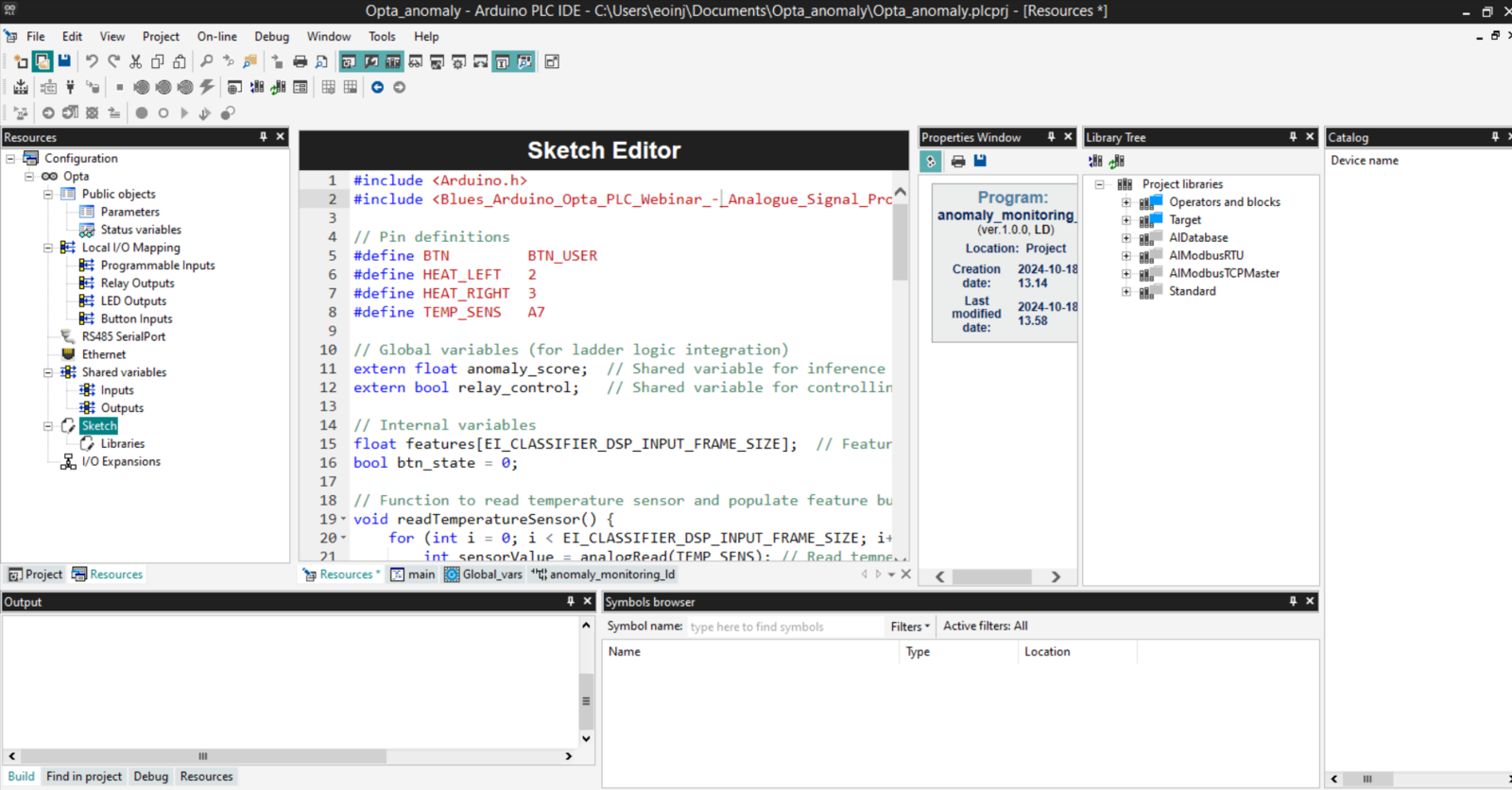
Monitor and Debug

Use the Watch window in the PLC IDE to monitor the shared variables and ensure the system responds correctly to anomalies detected by the machine learning model.

Upload the Arduino Sketch:

  • Ensure your Arduino sketch is uploaded to the Opta PLC to provide the inference results.

Run the Ladder Logic:

  • Start the ladder logic program from the Arduino PLC IDE.

  • Monitor the shared variables using the Watch window to see how the ladder logic reacts to the inference results.

Benefits of Ladder Logic Integration

  • Real-time Control: By integrating anomaly detection with ladder logic, you can implement real-time, intelligent control systems that take action based on data-driven decisions from the Edge Impulse model.

  • Easy Troubleshooting: Using ladder logic alongside machine learning allows for clear, visual representation of control logic, making it easier to debug and monitor the system's responses to anomalies.

  • Seamless PLC Integration: The Arduino PLC IDE provides a smooth environment for combining traditional control logic with modern machine learning, ensuring compatibility and ease of use.

Later will will revisit this with C++ and Siemens PLCs, for now, you can explore the Arduino PLC IDE.

Conclusion

Congratulations! You have successfully implemented anomaly detection on an Arduino Opta PLC using Edge Impulse. This tutorial demonstrates the seamless integration of machine learning models with industrial automation systems, enabling real-time monitoring and fault detection.

Please share your experiences and feedback with us on the Edge Impulse forum.

For more information on Edge Impulse and Arduino Opta PLC, visit the official websites:

  • Arduino Opta PLC

Troubleshooting

  • Arduino Cloud Issues: We are aware of issues with Arduino Cloud .properties file format vs IDE and are working with Arduino. If you have issues try moving the .properties file to the same folder as the .ino file and re-uploading the sketch.

Read on

here
Arduino OPTA plc
DIN Celsius
Wiring Diagram
Impulse Studio
Generate Features
Training Model
Model Validation
Arduino Cloud
Ladder Logic - Anomaly integration
Shared Variables
Ladder Logic Editor
Ladder Logic - Sketch Integration
Download Library
Blues Wireless