Installing dependencies
To set this device up in Edge Impulse, you will need to install the following software:- Edge Impulse CLI.
- Texas Instruments UniFlash
- Install the desktop version for your operating system here
- Add the installation directory to your PATH
- See Troubleshooting for more details
- On Linux:
- GNU Screen: install for example via
sudo apt install screen.
- GNU Screen: install for example via
Connecting to Edge Impulse
With all the software in place it’s time to connect the development board to Edge Impulse.1. Configure your hardware
To interface the Launchpad with sensor hardware, you will need to either connect the BOOSTXL-SENSORS to collect accelerometer data, or the CC3200AUDBOOST to collect audio data. Follow the guides below based on what data you want to collect.Before you startThe Launchpad jumper connections should be in their original configuration out of the box. If you have already modified the jumper connections, see the Launchpad’s User Guide for the original configuration.
Accelerometer Hardware Configuration Guide
Connecting the BOOSTXL-SENSORS board to the Launchpad is simple. Just orient the sensor board such that the3V3 and GND markings on the booster pack line up with the Launchpad, and then attach the booster pack to the top header pins of the Launchpad, as shown below:

Launchpad connected with sensor booster pack
Audio Hardware Configuration Guide
Extra Hardware Required You will need five extra 0.1” jumper wires to connect the CC3200AUDBOOST to the Launchpad, as described in the Texas Instruments documentation. The CC3200AUDBOOST board requires modifications to interface properly with the CC1352P series of Launchpads. The full documentation regarding these modifications is available from Texas Instruments in their Quick Start Guide, and a summary of the steps to configure the board are shown below.- Disconnect conflicting pins on the Launchpad.
Pins 26-30 on header J3 conflict with the CC3200AUDBOOST pins and need to be disconnected. To do this easily, TI recommends bending the pins down as shown below.
Disconnected pins on the CC1352P Launchpad
Launchpad modifications are compatible across booster packs
All Edge Impulse supported booster packs do not usepins 26-30 on header J3. If you have modified your Launchpad to interface with the audio booster pack, you can leave these pins disconnected when connecting other boards.
-
Connect jumper wires to the required pins
The pin connections shown below are required by TI to interface between the two boards. Connect the pins by using jumper wires and following the diagram. For more information see the CC3200AUDBOOST User Guide and Quick Start Guide
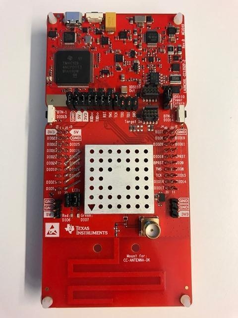
With the pins connected, your board should appear as shown below.
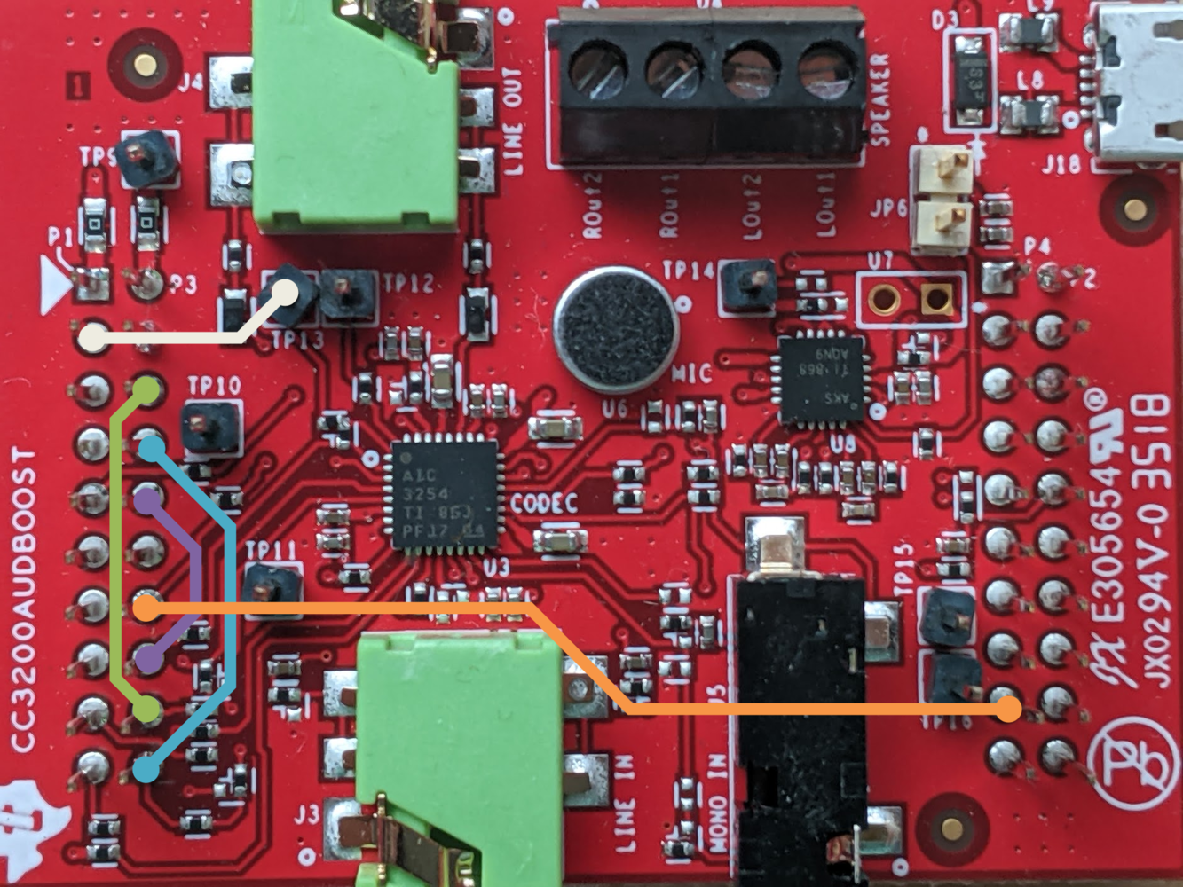
Jumper connections for CC3200AUDBOOST
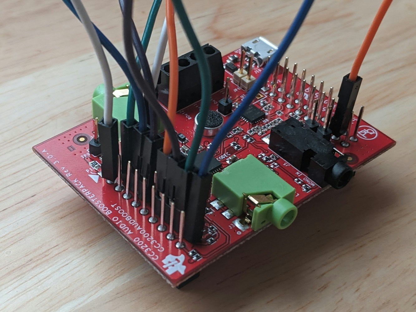
Properly configured CC3200AUDBOOST
-
Align the
P1pin on the booster pack with3V3pin on the Launchpad, and connect the two boards together.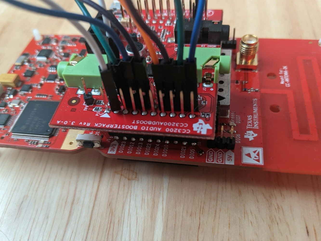
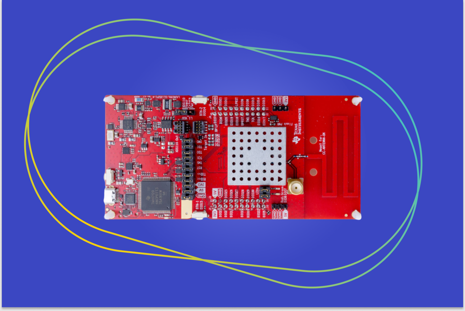
TI Launchpad connected with audio booster pack
Using Audio and Accelerometer Hardware Simultaneously
In most cases it is possible to connect the sensor and audio booster pack at the same time. Allowing you to quickly switch between accelerometer and audio data collection. The primary constraint is that the BOOSTXL-SENSORS board must not have the TMP007 temperature sensor soldered on, as this conflicts with the audio interface when both booster packs are connected.-
Ensure that the TMP007 temperature sensor is not present on the sensor booster pack. The board should have an unpopulated footprint for
U5as shown below: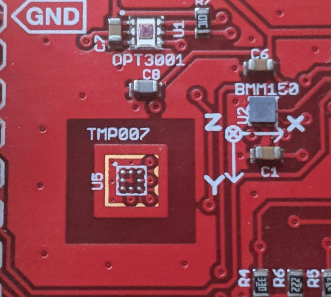
Unpopulated TMP007 footprint on sensor booster pack
- Perform all modifications to the Launchpad and audio booster pack described in the Audio Hardware Configuration Guide
-
Connect the BOOSTXL-SENSORS booster pack directly to the Launchpad.
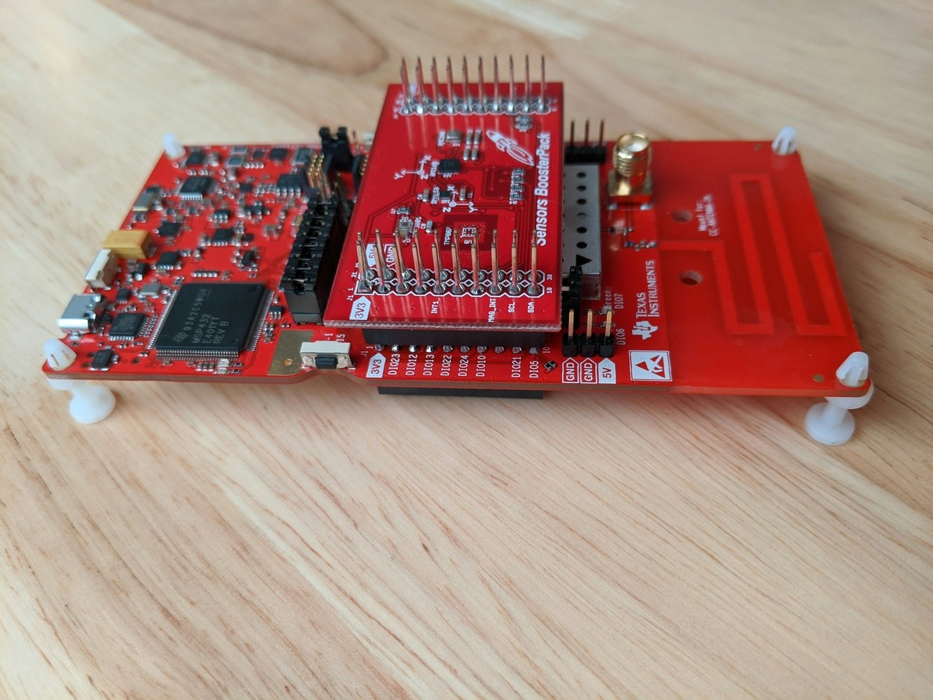
Launchpad connected with sensor booster pack
-
Connect the audio booster pack on top of the sensors booster pack. The final board should appear as shown below:
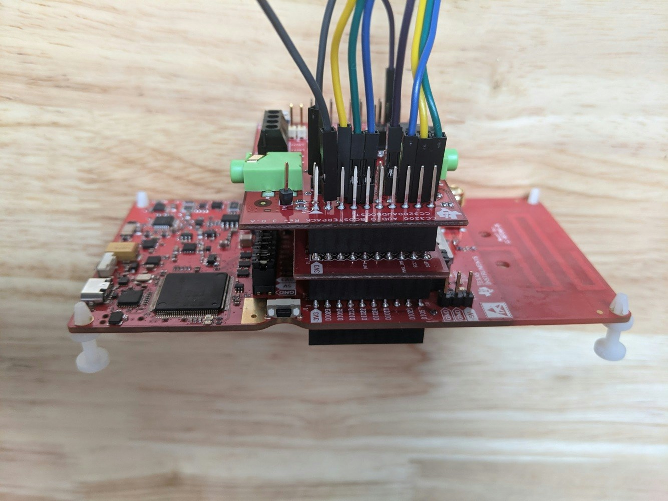
Launchpad connected with sensor and audio booster packs
2. Connect the development board to your computer
Use a micro-USB cable to connect the development board to your computer.3. Update the firmware
The development board does not come with the right firmware yet. To update the firmware:- Download the latest Edge Impulse firmware, and unzip the file.
- Open the flash script for your operating system (
flash_windows.bat,flash_mac.commandorflash_linux.sh) to flash the firmware. - Wait until flashing is complete, and press the RESET button once to launch the new firmware.
4. Setting keys
From a command prompt or terminal, run:--clean.
Which device do you want to connect to?
The Launchpad enumerates two serial ports. The first is the Application/User UART, which the edge-impulse firmware communicates through. The other is an Auxiliary Data Port, which is unused.
When running the edge-impulse-daemon you will be prompted on which serial port to connect to. On Mac & Linux, this will appear as:
5. Verifying that the device is connected
That’s all! Your device is now connected to Edge Impulse. To verify this, go to your Edge Impulse project, and click Devices. The device will be listed here.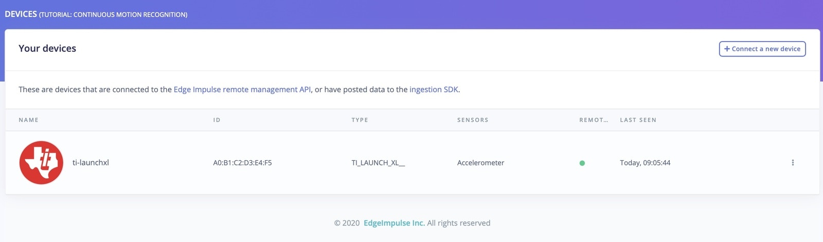
Device connected to Edge Impulse
Next steps: building a machine learning model
With everything set up you can now build and run your first machine learning model with these tutorials: Looking to connect different sensors? The Data forwarder lets you easily send data from any sensor into Edge Impulse, and you can [run your impulse locally]/run-inference/cpp-library/) with custom firmware or sensor data.Troubleshooting
Failed to flash If the UniFlash CLI is not added to your PATH, the install scripts will fail. To fix this, add the installation directory of UniFlash (example/Applications/ti/uniflash_6.4.0 on macOS) to your PATH on:
If during flashing you encounter further issues, ensure:
- The device is properly connected and/or the cable is not damaged.
- You have the proper permissions to access the USB device and run scripts. On macOS you can manually approve blocked scripts via
System Preferences->Security Settings->Unlock Icon - If on Linux you may want to try copying tools/71-ti-permissions.rules to /etc/udev/rules.d/. Then re-attach the USB cable and try again.
gcc/build/edge-impulse-standalone.out binary file may be flashed to the Launchpad using the UniFlash GUI or web-app. See the Texas Instruments Quick Start Guide for more info.