Note: This devkit does not support stacking the shield directly. You’ll need to manually wire the IKS02A1 shield to the DK. A wiring diagram is available below.If you prefer a different sensor, you can also use the Data forwarder, or modify the example firmware (built with nRF Connect SDK and Zephyr RTOS) to support any Zephyr-compatible accelerometers. The Edge Impulse firmware for this development board is open source and hosted on GitHub: edgeimpulse/firmware-nrf54l15.
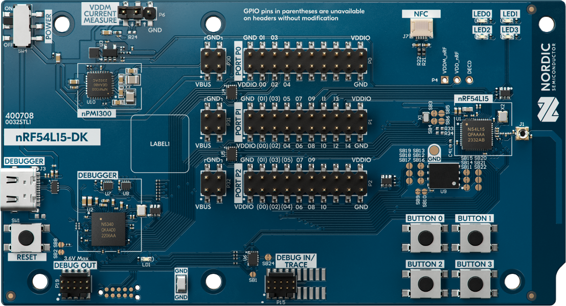
nRF54L15 DK board
Connecting to Edge Impulse
With software in place, here’s how to wire and connect the devkit.1. Wiring the IKS02A1 MEMS sensor shield
Unlike the nRF9161 DK, the nRF54L15 DK does not support direct stacking with the IKS02A1 shield. You must wire it manually. Use the following connections: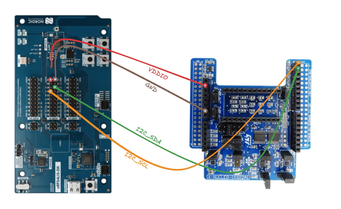
Wiring Diagram Placeholder
2. Connect the development board to your computer
Use a USB-C cable to connect the board. Then set the power switch to “on”.3. Download the latest Edge Impulse firmware
Download the latest Edge Impulse Nordic Semi nRF54L15 DK firmware.4. Flash the Edge Impulse firmware
- Connect the board over USB and ensure it appears as a JLINK USB device.
- Install and open the nRF Connect for Desktop and go to the Programmer application
- Drag and drop the
nrf54l15-dk-full.hexfirmware from the downloaded zip in this Programmer application (this firmware contains both application and networking core firmware). - Click “Erase & Write” and wait for device to boot up.