Introduction:
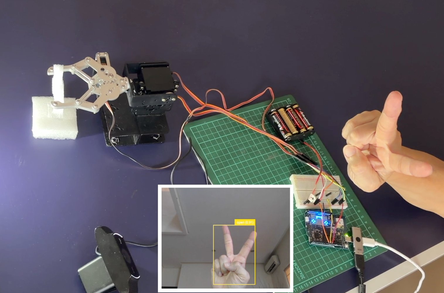
This project utilizes a local network setup where an Arduino UNO Q is connected to a USB camera and a robotic arm, with programming performed via the Arduino App Lab on our computer/laptop. The ease of using the I/O pins on the Arduino UNO Q, which are identical to those of a standard Arduino Uno, makes this project accessible and easy for anyone to carry out. In this relatively simple project, the system will translate the position of hand detected into movements of two servos that control the pan-tilt mechanism on robotic arm, while gesture types (for example, open and close) will control the servo on the claw/gripper. The system can use an existing model (Hand Gesture) available in Arduino App Lab, or a custom model created in Edge Impulse Studio integrated within App Lab. The model will be deployed in Python code for the program logic and then passed to the Arduino Sketch to drive the servos accordingly. This project is intended as a basic implementation of object detection in robotics, featuring real-time object tracking and intuitive robotic arm movement. It is a foundation for applications in more complex robotic systems.Hardware Component:
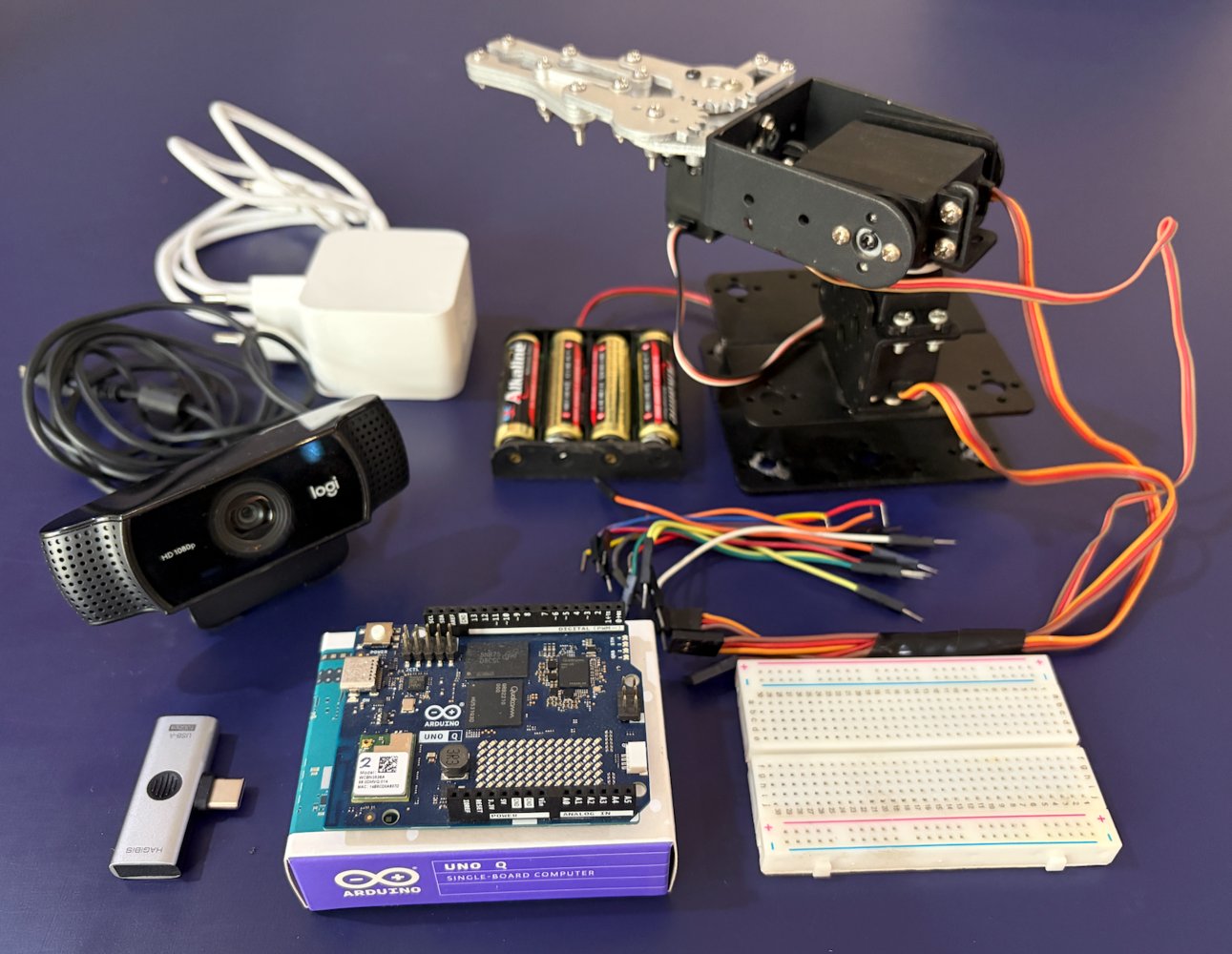
- Arduino UNO Q (2GB or 4GB)
- USB-C Power Adaptor (eg. 27W Pi 5 Power adapter)
- PC/laptop
- USB-C to USB-A hub with PD (except from Apple) or official Arduino USB-C hub (8 in 1)
- USB Camera/webcam (eg. Logitech C920/C922)
- 3 DoF Robotic arm with gripper
- 3 pcs Servos (eg. MG996r)
- Breadboard + jumper cables
- 4 x1,5V battery or 6V power supply
Software & Online Services:
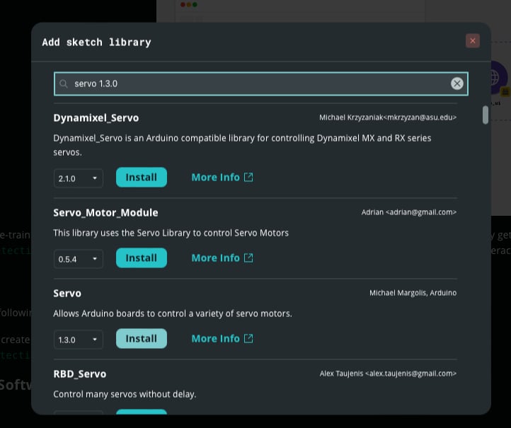
- Arduino App Lab (v 0.8.0)
- Edge Impulse Studio
Steps:
1. UNO Q Setup and Arduino App Lab
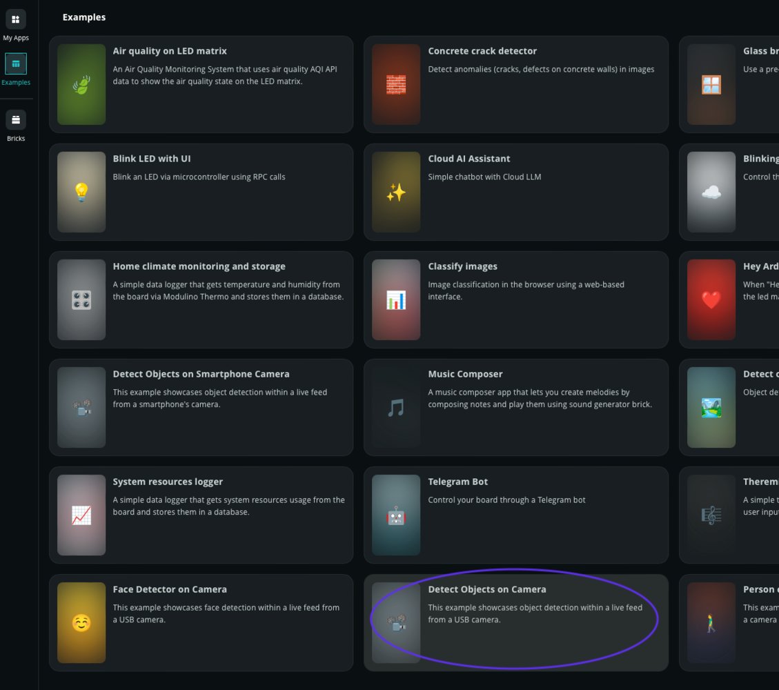
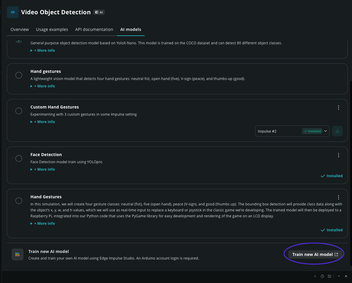
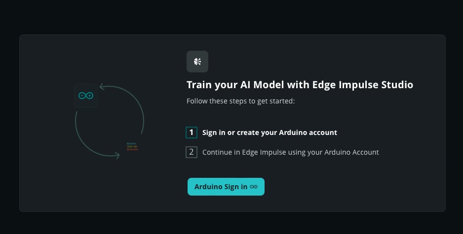
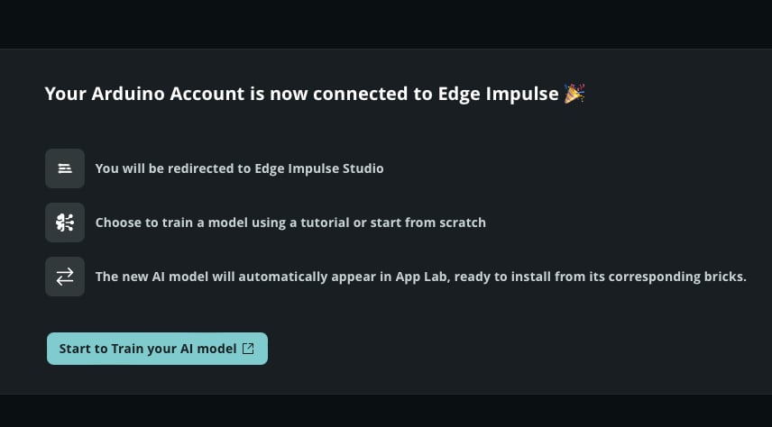
For the initial setup, install the Arduino App Lab on your computer and connect the Arduino UNO Q via a USB-C connection (PC-hosted mode). Once App Lab is opened, the UNO Q device will appear; select it, create an access password, and configure the Wi-Fi network so that we can use it in local network mode for convenience. After completing this process, disconnect the UNO Q and connect it to a power adapter. Open the Arduino App Lab on your computer, and the UNO Q will appear for you to access. To familiarize yourself with this ecosystem, you can select one project from Examples and press Run, which will upload and execute the chosen program on the UNO Q. For the next step, create our project by duplicating “Detect Objects from Camera” from the Examples, because it’s using similar bricks. Open it and click Copy and edit (in the upper right corner), then rename it as desired, for example: “Custom Hand Gestures Detection.” Next, select the AI models tab and click Train new AI model, which will allow you to access Edge Impulse Studio using your Arduino account (sign in or create one if you don’t have one yet). Then, you will be redirected to the Edge Impulse Studio by clicking Start to Train your AI model. We will discuss the stages within Edge Impulse Studio in the next step below.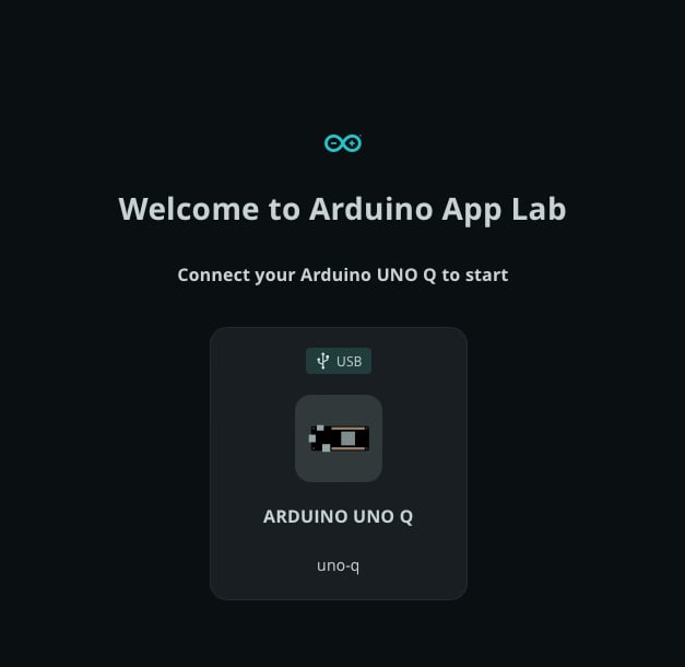
2. Collecting Data
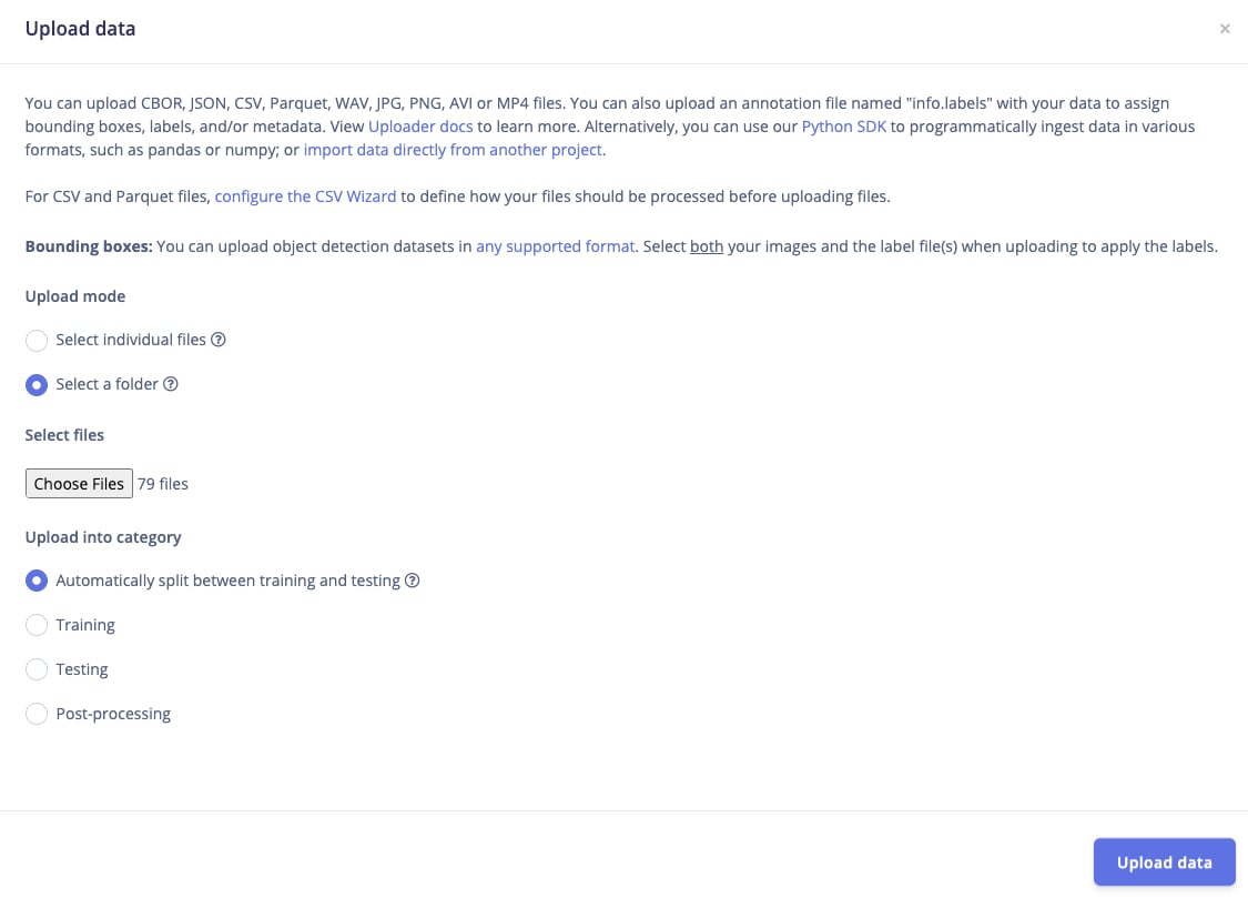
Before we start uploading the photos, we will create three labels/classes: a closed hand (neutral), and a scissor-like hand gesture (open and close). Capture these photos using your camera or your laptop’s built-in webcam. I recommend taking a variety of 30-40 photos for each type, which should be sufficient for this project. Save them in folders, and we will continue in the Edge Impulse Studio. For those who are not familiar with Edge Impulse Studio, choose Images project option, then Object detection. In Dashboard > Project Info, choose Bounding Boxes for labeling method and UNO Q for target device. Then in Data acquisition, click on Upload Data tab. Choose you saved folder then upload.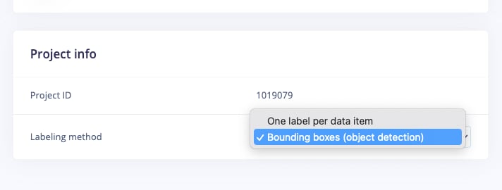
3. Labeling
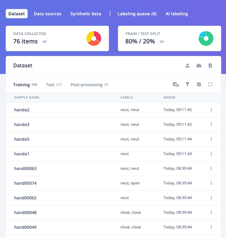
The next step is labeling, now click on Data Acquisition, click on Labeling queue tab, then start drag a box around an object and label it and Save. Repeat.. until all images labelled. After labeling, it’s recommended to split the data into training and testing sets, around an 80/20 ratio. If you haven’t done this yet, click on Train / Test Split to automate this process.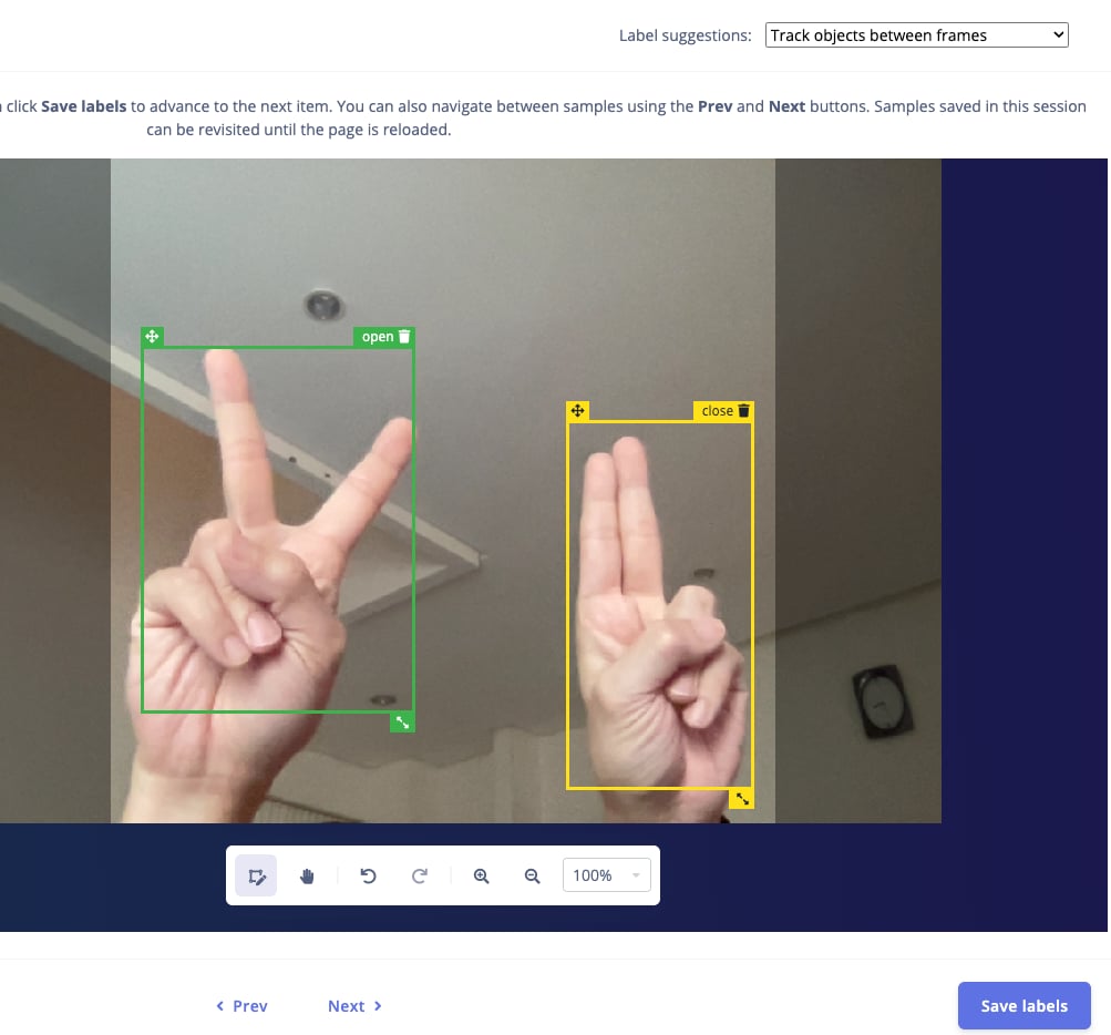
4. Train, Build, Deploy
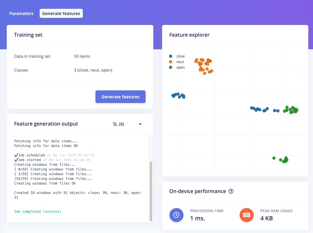
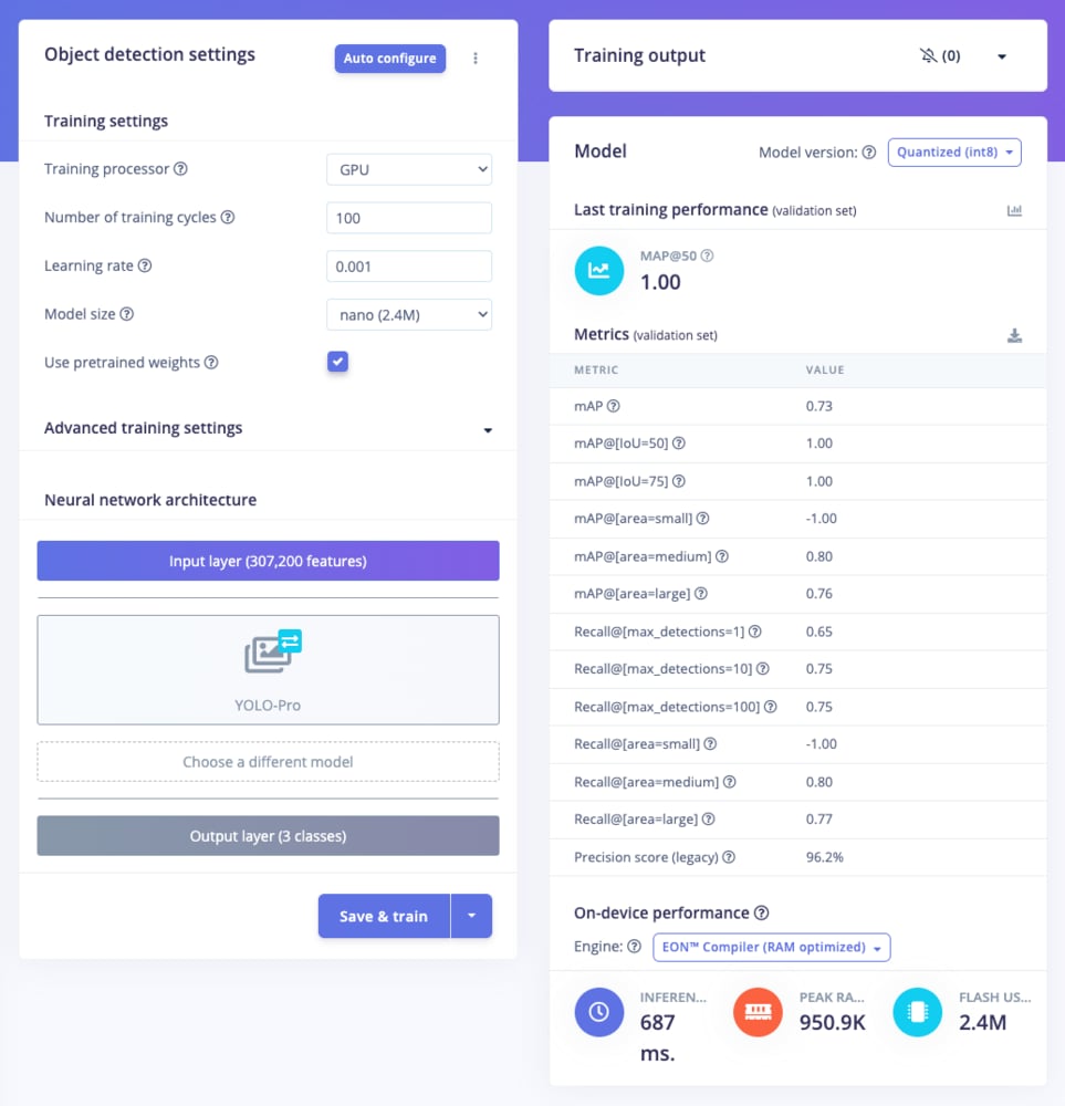
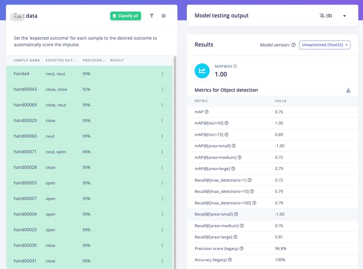
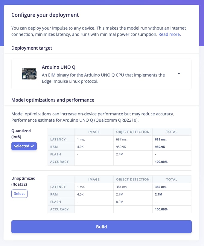
Once your labelled dataset is ready, go to Impulse Design > Create Impulse, and set the image width and height (eg. 320x320). Choose Fit shortest axis, then select Image and Object Detection as the learning blocks, and click Save Impulse. Next, navigate to the Image Parameters section, select RGB as the color depth, and press Save parameters. After that, click on Generate, where you’ll be able to see a graphical distribution. Now, move to the Object Detection section and configure the training settings. Select GPU and set the training cycles to around 100, learning rate to 0.001 and medium for model size. Choose YOLO-Pro or MobileNetV2 SSD FPN-Lite as the NN architecture. Once done, start training by pressing Start, and monitor the progress. If everything goes well; eg MAP@50 = 1.0 or the precision result is more than 90%, proceed to the next step. Go to the Model Testing section, click Classify all, and if the MAP@50 = 1.0 or the accuracy is around 90%, you can move on to Deployment. Select deployment target Arduino UNO Q, select quantized (int 98) then click Build. Next step will be on Arduino App Lab.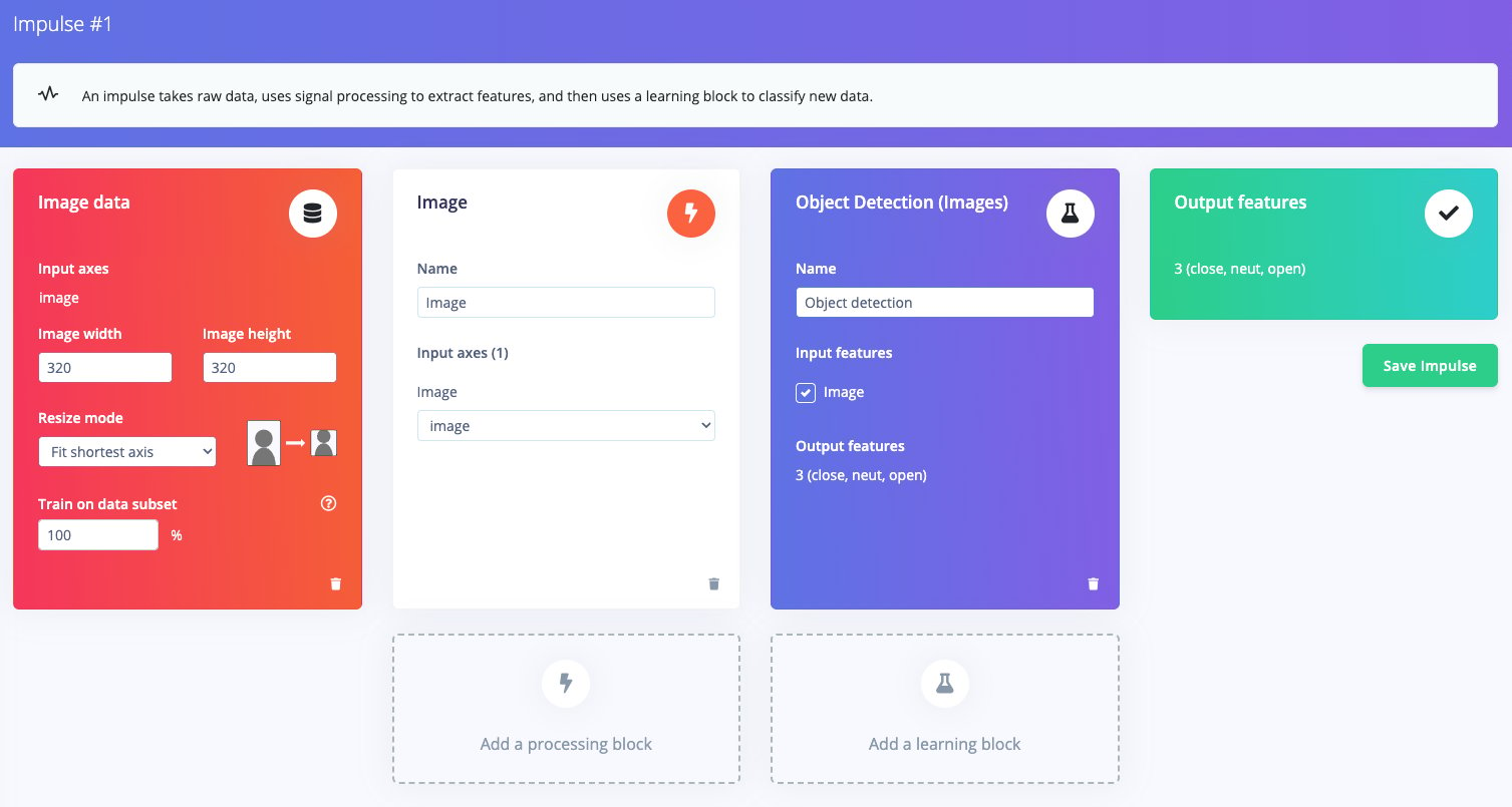
5. Test on UNO Q
After the model has been built, return to the Arduino App Lab, you will find the custom model we built in Edge Impulse Studio earlier-click the Download icon and select it. Now, our custom model is ready to use. To test it, don’t forget to connect the USB-C to USB-A hub and the USB camera to your UNO Q. Then, click Run in App Lab; the upload and execution process on the UNO Q will begin. If everything goes smoothly, the WebUI-HTML program will display live object detection inference in your computer’s browser. Try the 3 types of gestures from our model to ensure it is working properly.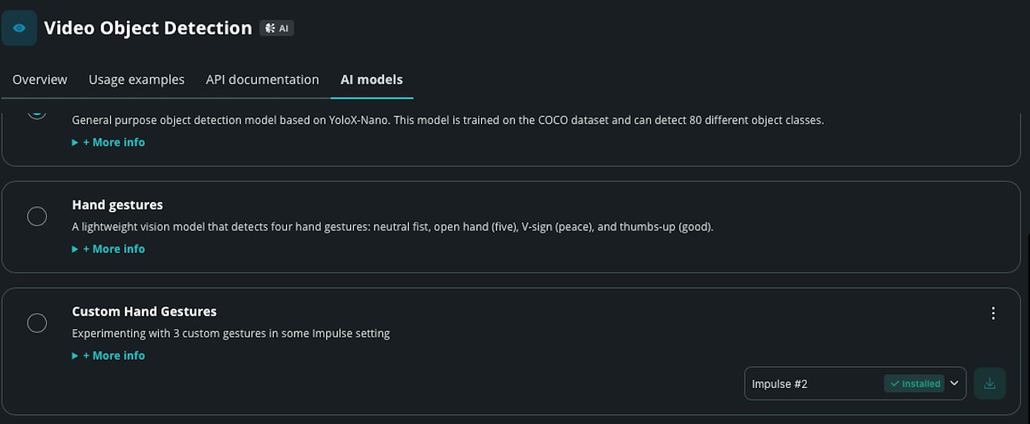
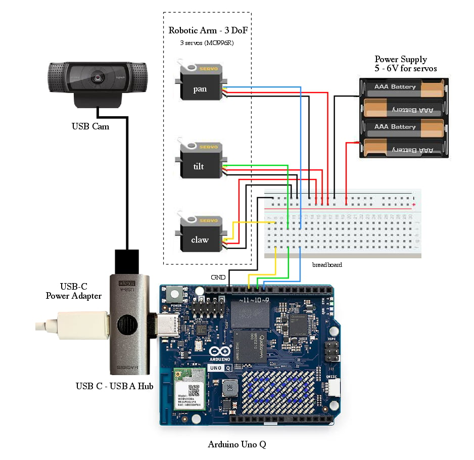
6. Build Your System: UNO Q + usb camera + robotic arm + program