Introduction
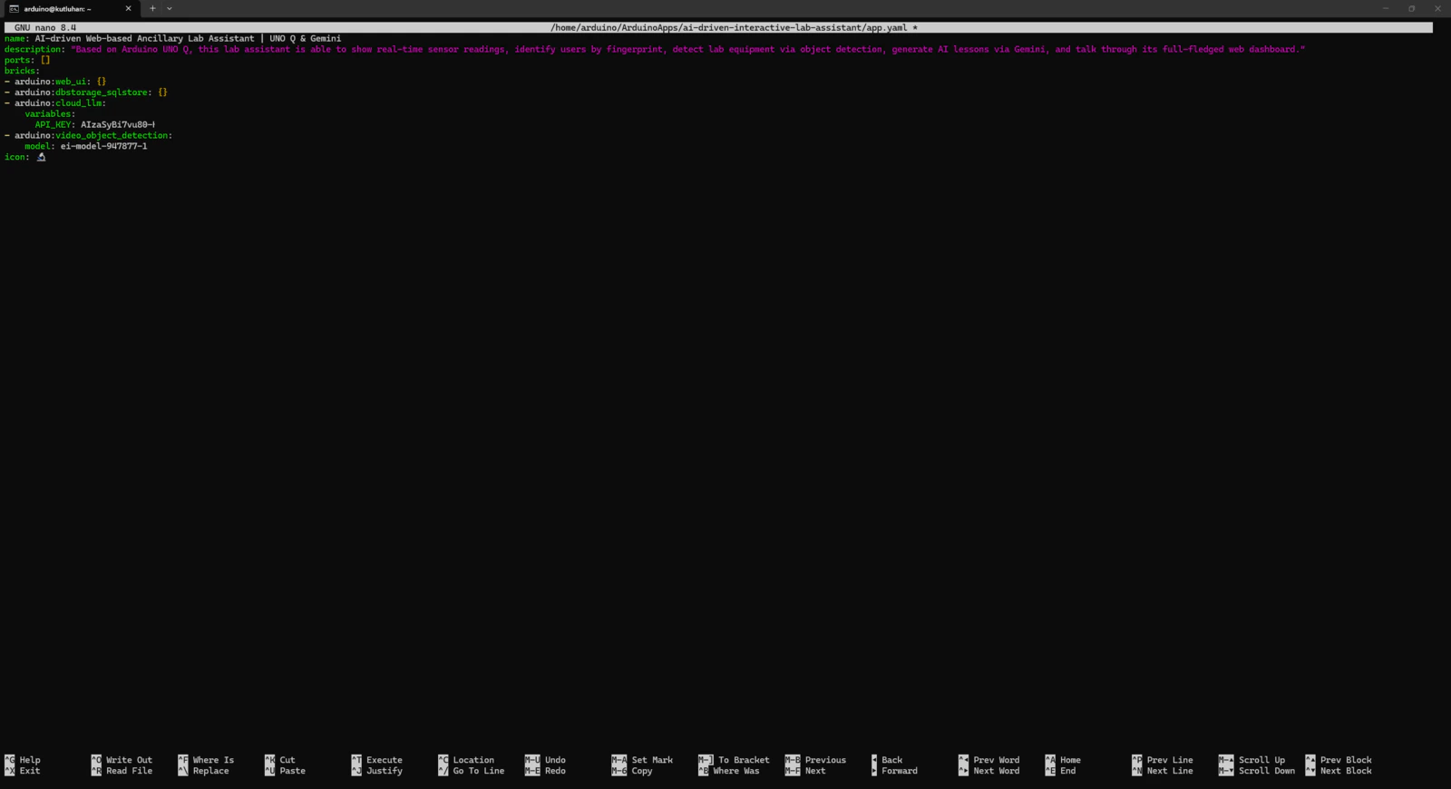
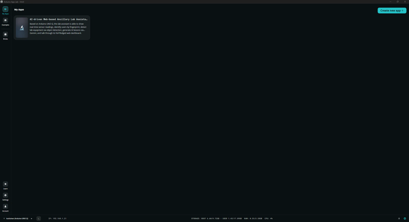
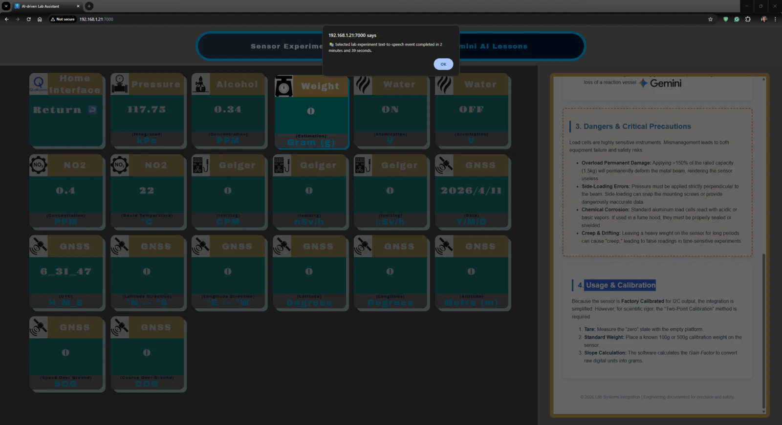
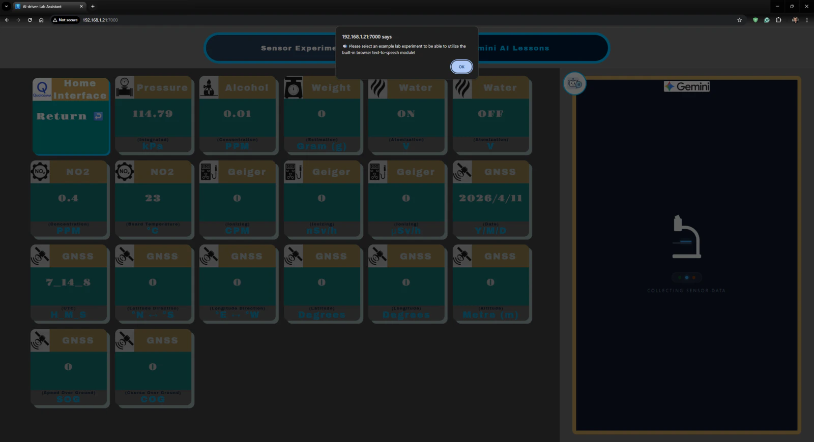
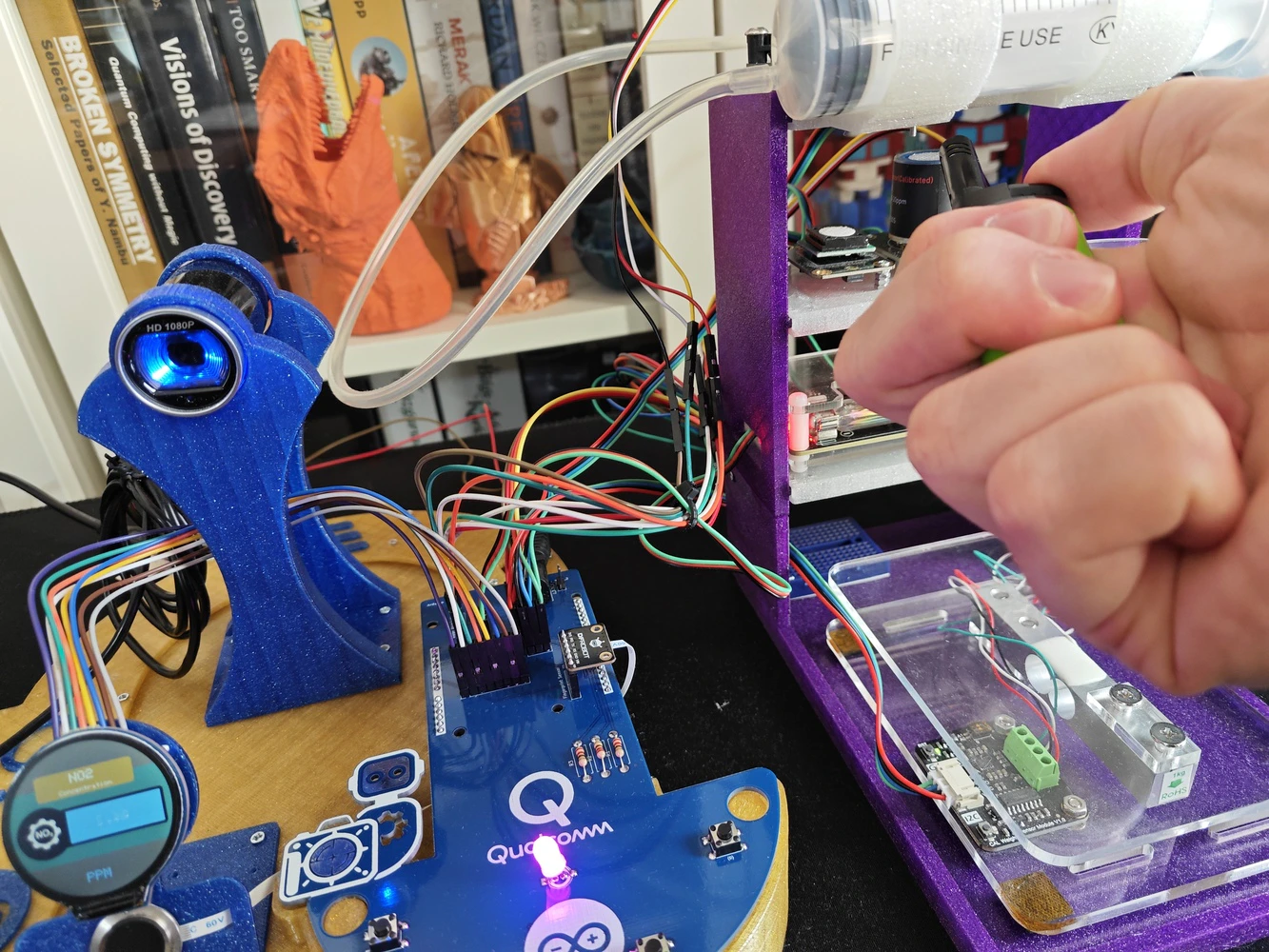
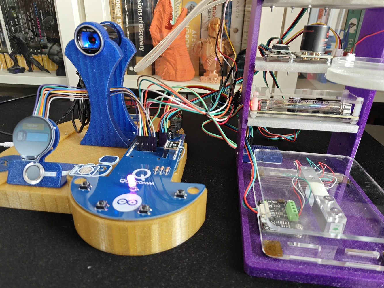
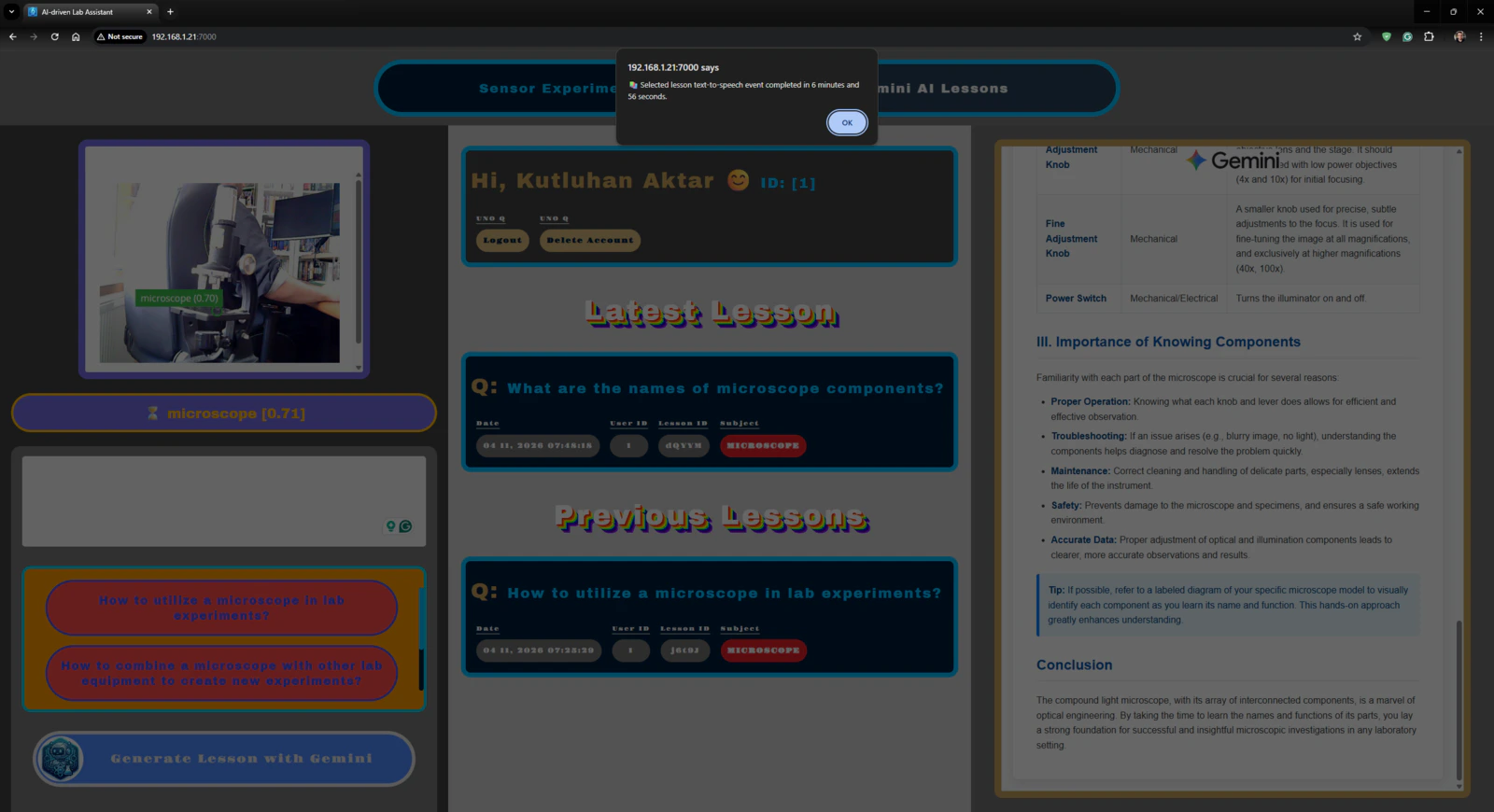
After hearing about the launch of the brand-new Arduino UNO Q, designed as the first SBC (single-board computer) with Arduino’s philosophy of bridging the gap between employing professional development tools and implementing them as novices when creating introductory projects or as experts while prototyping complex mechanisms rapidly yet stably, I thought it would be a great opportunity to redesign my previous AI-driven lab assistant project and enable more developers, beginner or expert, to replicate, experiment, or improve this new AI-based ancillary lab assistant thanks to the built-in Arduino UNO Q features and its beginner-friendly development platform — Arduino App Lab. As you may know, if you have read one of my previous project tutorials, I prefer building my AIoT projects on the target development boards and environments from scratch and enjoy developing unique methods, applications, and mechanisms to collect custom training data and achieve intended device features, strictly following my methodology of developing proof-of-concept research projects. Nonetheless, in this project, I heavily focused on developing all lab assistant features based on the provided UNO Q and Arduino App Lab characteristics, such as the built-in Bricks, native microprocessor-microcontroller communication procedure, and Linux-oriented SBC board architecture, to ensure that anyone with a UNO Q can effortlessly replicate and examine this lab assistant without needing to have a deep understanding of all aspects of this project; coding, web design, neural network training, LLM-implementation, 3D modeling, etc. In this regard, I hope this project serves as an entry point for developing research projects, encouraging readers to reverse-engineer the features of this AI-driven lab assistant to gain a deeper understanding of AIoT development on the edge. As I was taking inspiration from my previous lab assistant project, I heavily modified the device structure and added a lot of new features specific to this iteration, for instance, designing a unique PCB (UNO Q shield) for utilizing various lab sensors to conduct LLM-assisted basic lab experiments. After months of hard work, I managed to complete the reimagined AI-driven ancillary lab assistant structure and develop all the features I envisioned on UNO Q by solely employing the Arduino App Lab development environment, providing foundational building blocks (Bricks). 🤖 To build the ancillary lab assistant structure: ✍🏻 I designed a unique PCB as a UNO Q shield (hat) to connect the selected lab sensors and create the analog lab assistant interface, including the capacitive fingerprint sensor. ✍🏻 Then, I modeled 3D parts to design the ancillary lab assistant base, containing the USB camera and the analog interface. ✍🏻 Finally, I designed a modular lab sensor ladder, organizing all sensors and secondary experiment tools, to create a compact but easy-to-use instrument. 🤖 To accomplish all of the ancillary lab assistant features I contemplated, performed by an Arduino App Lab application: 🛠️ I trained an Edge Impulse object detection model to identify various lab equipment. 🛠️ I programmed the MCU (STM32) to collect real-time sensor information and manage the analog lab assistant interface. 🛠️ I developed a feature-rich web dashboard as the primary user interface and control panel of the lab assistant, hosted directly by the Arduino App Lab. 🛠️ I incorporated Google Gemini to enable the lab assistant to generate LLM-based lessons about the detected lab equipment. 🛠️ Thanks to the built-in background Linux MPU-MCU communication service (Arduino Router), I built the interconnected interface background in Python, handling the data transfer between the web dashboard, the analog interface (MCU), and the Qualcomm QRB (MPU) running the essential App Lab Bricks (Docker containers); database registration, inference running, web dashboard (UI) hosting, etc. 🤖 The finalized ancillary lab assistant allows users to: 🔬 create web dashboard accounts and sign in via fingerprint authentication, 🔬 monitor real-time lab sensor readings via the analog interface or the web dashboard, 🔬 inspect LLM-generated sensor guides and experiment tips for each lab sensor via the web dashboard, 🔬 capitalizing on the built-in browser text-to-speech (TTS) module, listen to LLM-generated sensor guides and experiment tips, 🔬 identify lab equipment via the provided Edge Impulse FOMO object detection model, 🔬 use the predefined equipment questions or enter a specific one to generate AI lessons through Google Gemini, 🔬 access the list of LLM-generated lessons assigned to your account on the web dashboard anytime, 🔬 study LLM-generated lessons by reading or listen to them via the TTS module. 🎁 📢 Although I did not utilize any service or product specifically sponsored for this project, I send my kind regards to DFRobot and Seeed Studio since some of the sensors were sponsored by them for my previous projects :)Development process, thinking in terms of creating an Arduino App Lab application, and final results
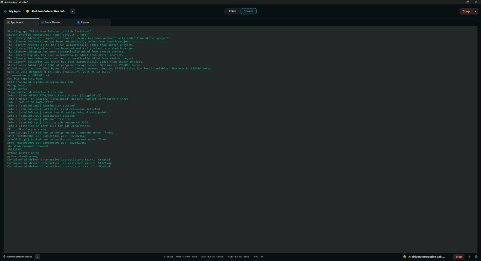
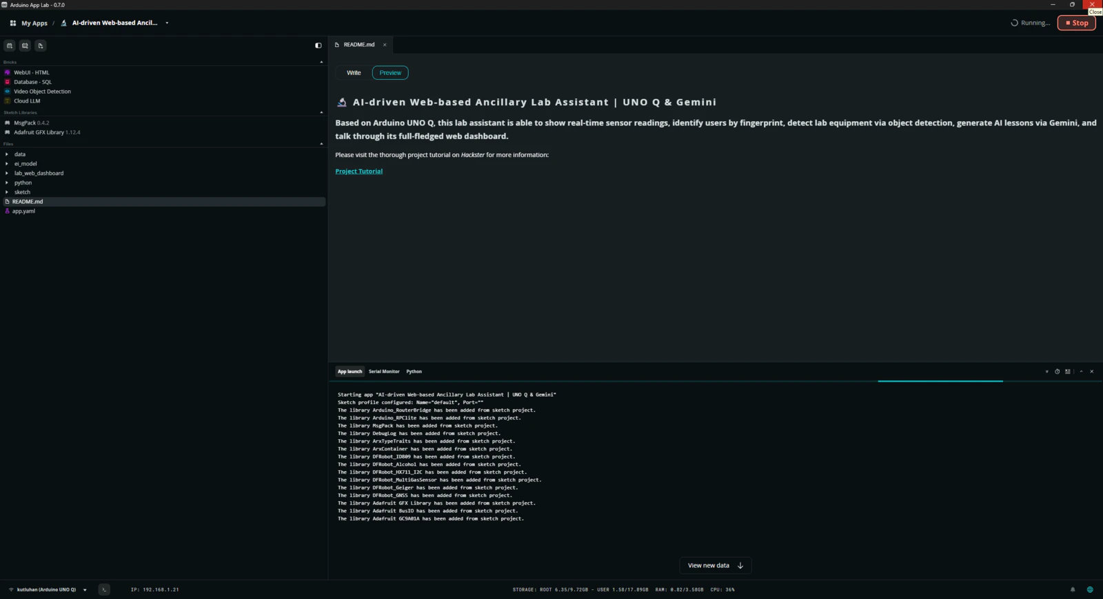
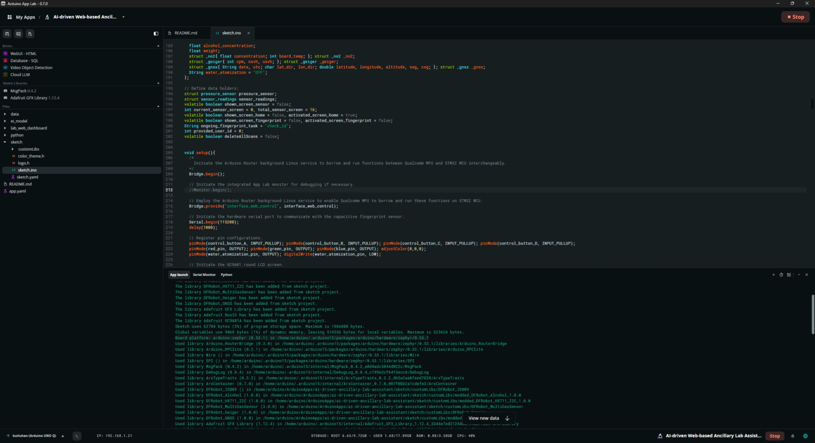
As mentioned in the introduction, the development process of this AI-driven lab assistant differs quite a bit from my previous AIoT projects since I built a single application within the confines of the Arduino App Lab development environment, specifically constructed to capitalize on the dual-brain (MPU-MCU) nature of UNO Q, even though I developed a feature-rich web dashboard and analog lab assistant interface individually. Arduino App Lab provides built-in Bricks (Docker containers) for adding various fundamental attributes to an App Lab application, such as web UI hosting, inference running for custom models, etc., and manages all of the operations of the included Bricks while executing the completed application. Thus, although I still utilized specific programming languages to develop the different aspects of the lab assistant App Lab application, Arduino for programming the STM32 microcontroller (MCU), Python for the application backend (Qualcomm MPU), and HTML, CSS, JavaScript for the web dashboard, as a whole, I built a single application that the App Lab runs and manages. I think the most prominent feature of UNO Q, with the support of the App Lab, is the built-in RPC (Remote Procedure Call) managed by the Arduino Router background Linux service, which enables developers to borrow and run functions between Qualcomm MPU and STM32 MCU interchangeably. App Lab also provides a built-in web socket to establish data transfer between the web dashboard and the Python backend. In this regard, it makes the communication between the STM32 MCU and the web dashboard effortless through the same Python backend. In light of these built-in features, I decided to build the second iteration of my AI-driven lab assistant with UNO Q. Generally, I thoroughly explain the setup process of my interconnected software and hardware applications according to the employed development boards, modules, environments, third-party APIs, etc. However, since I only utilized the built-in Arduino App Lab attributes to enable anyone with a UNO Q to replicate and examine this project effortlessly, I highly recommend inspecting the official Arduino UNO Q specifications and tutorials.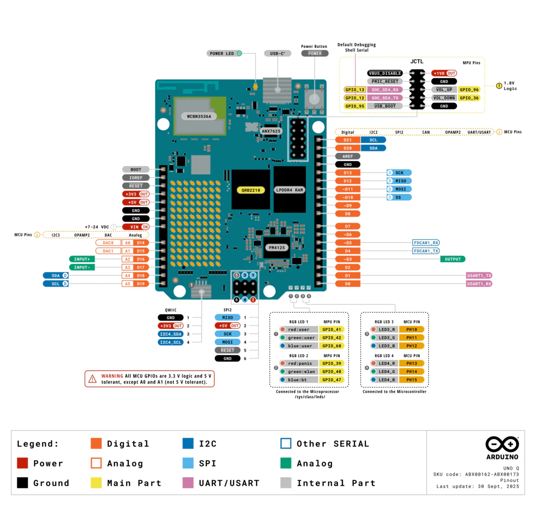
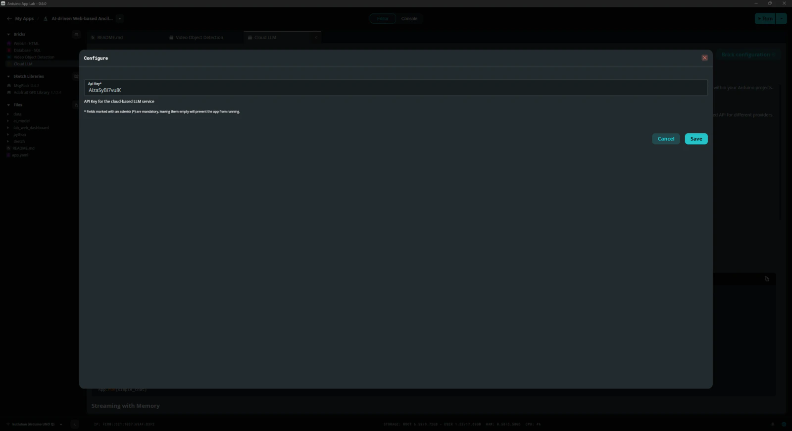
Step 0: Integration and use cases of Google Gemini
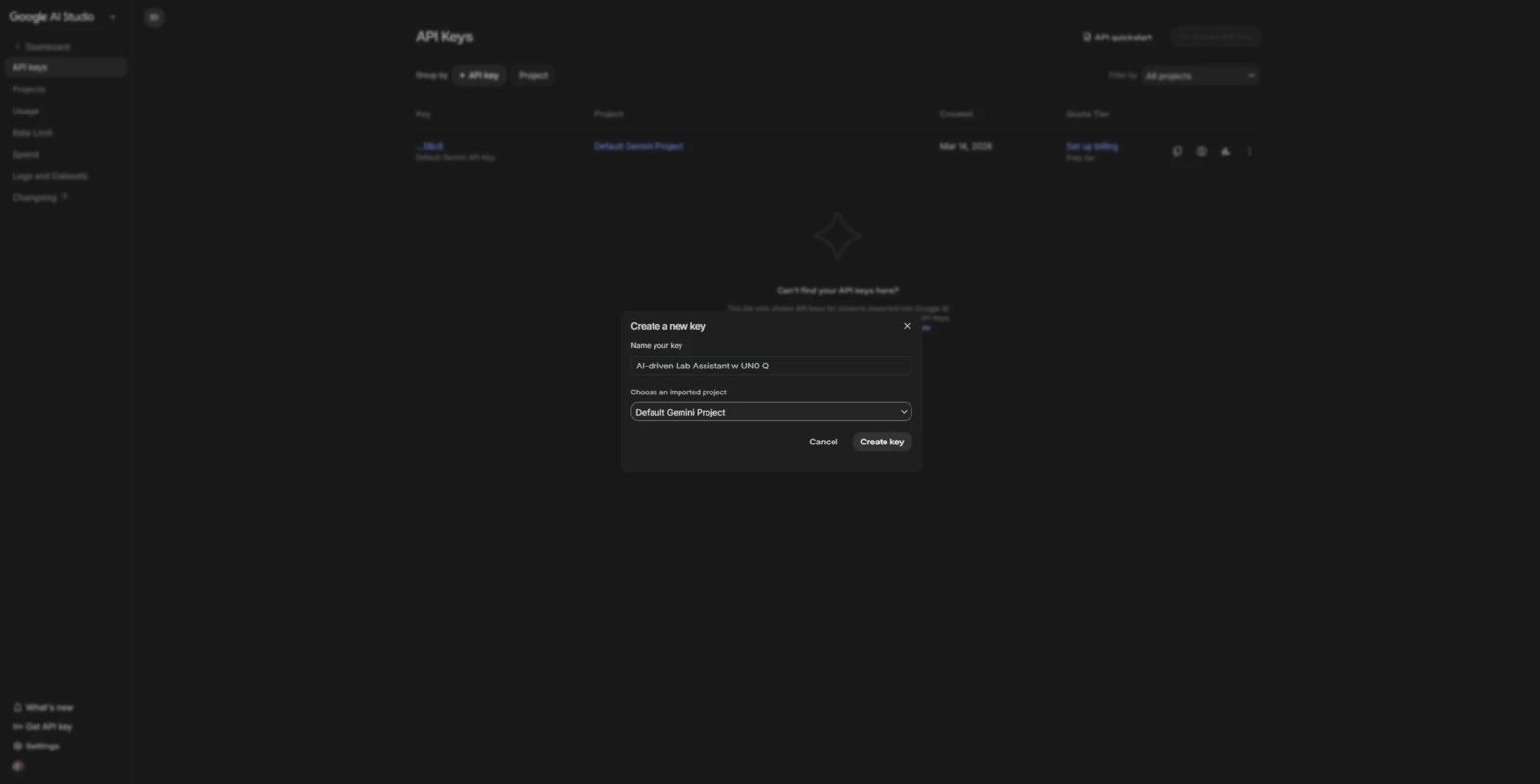
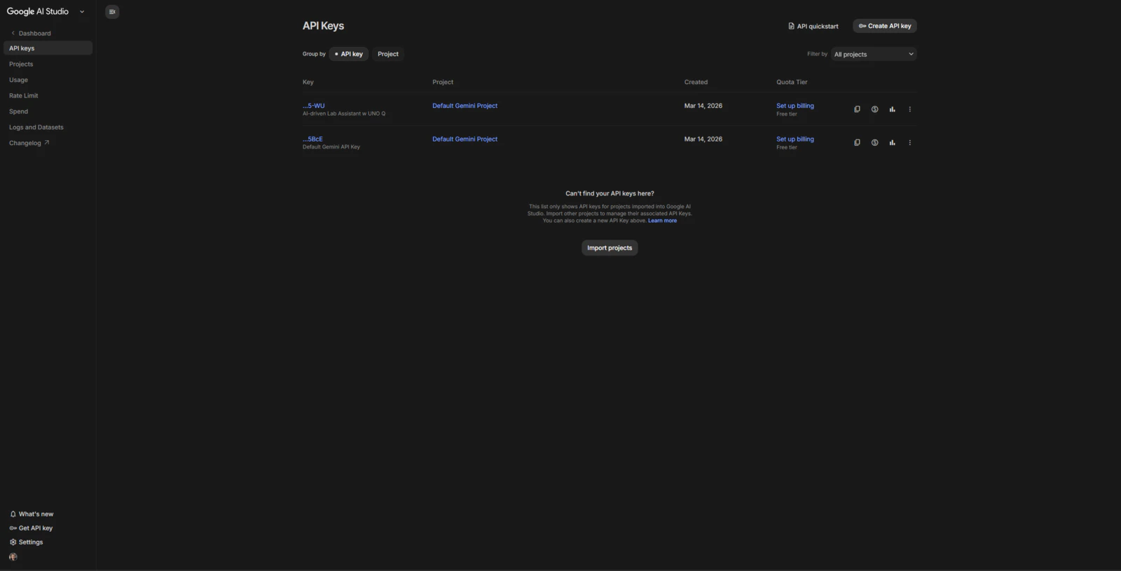
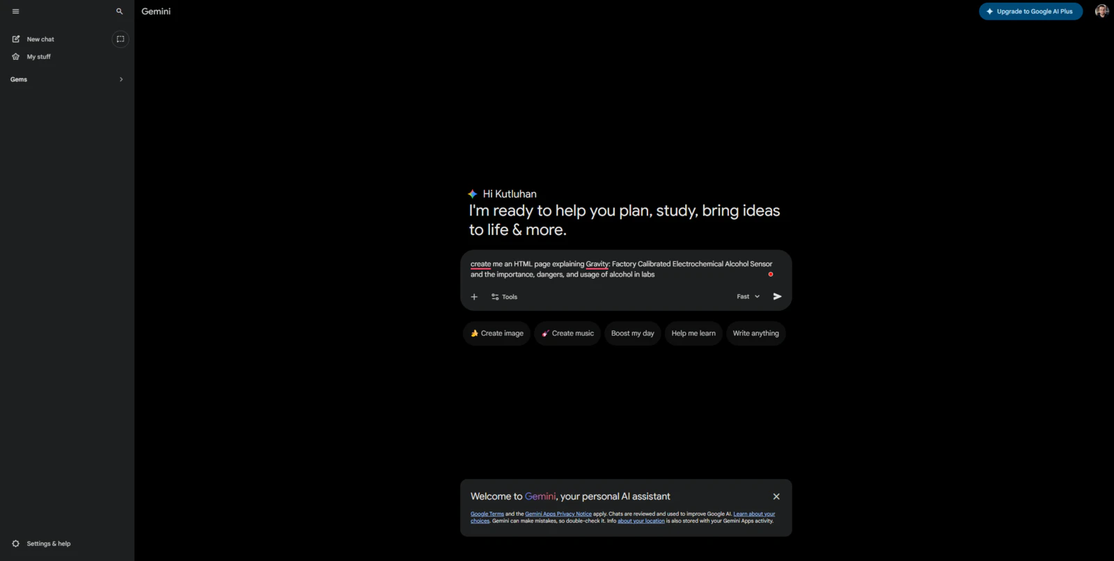
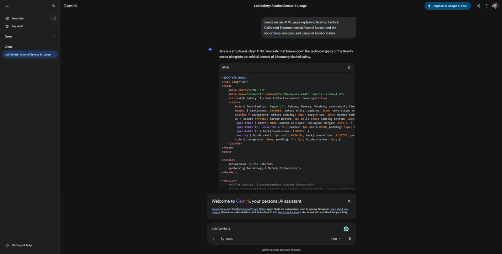
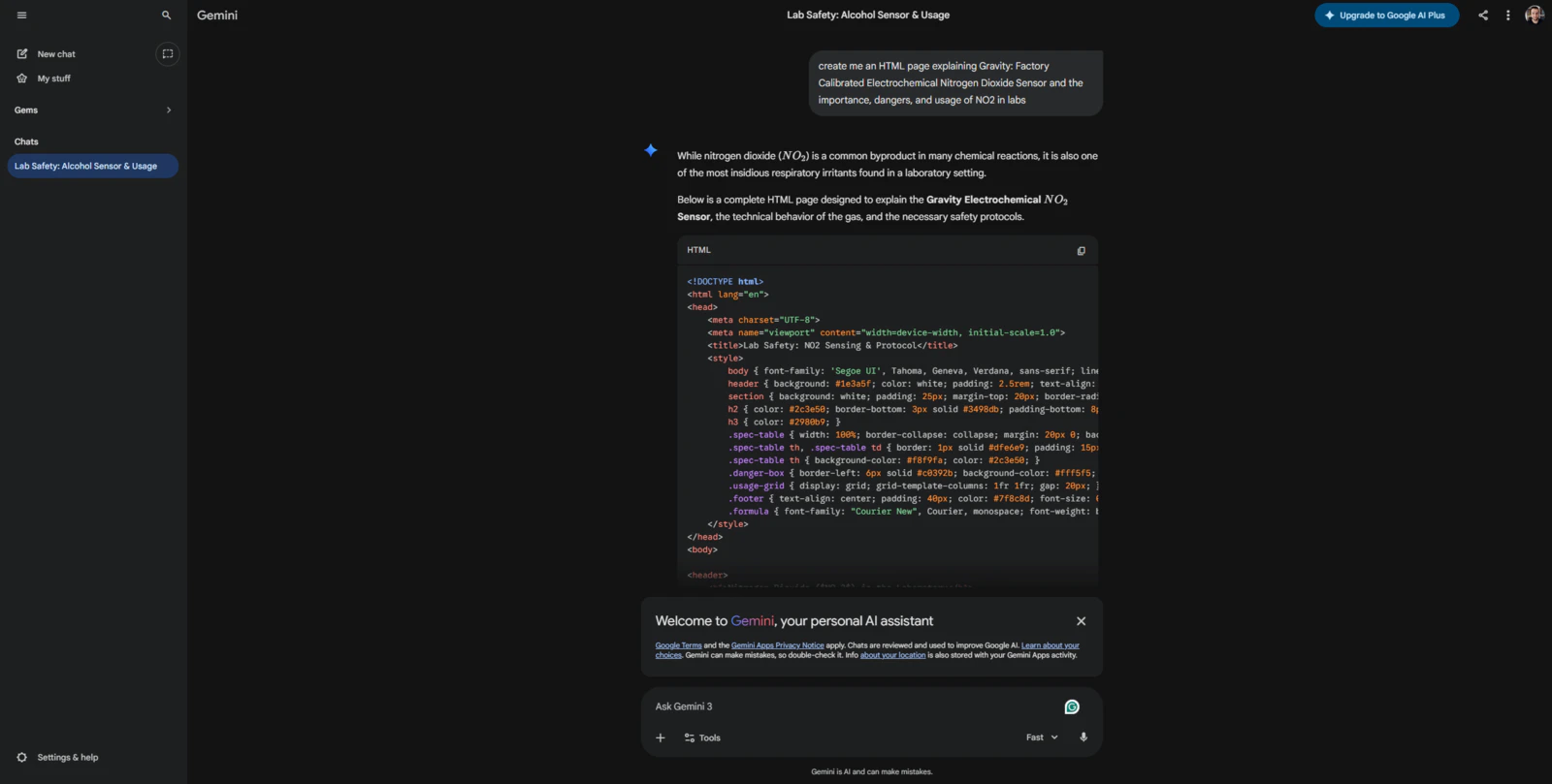
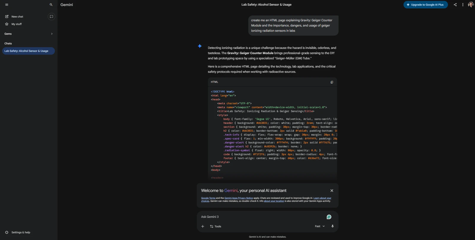
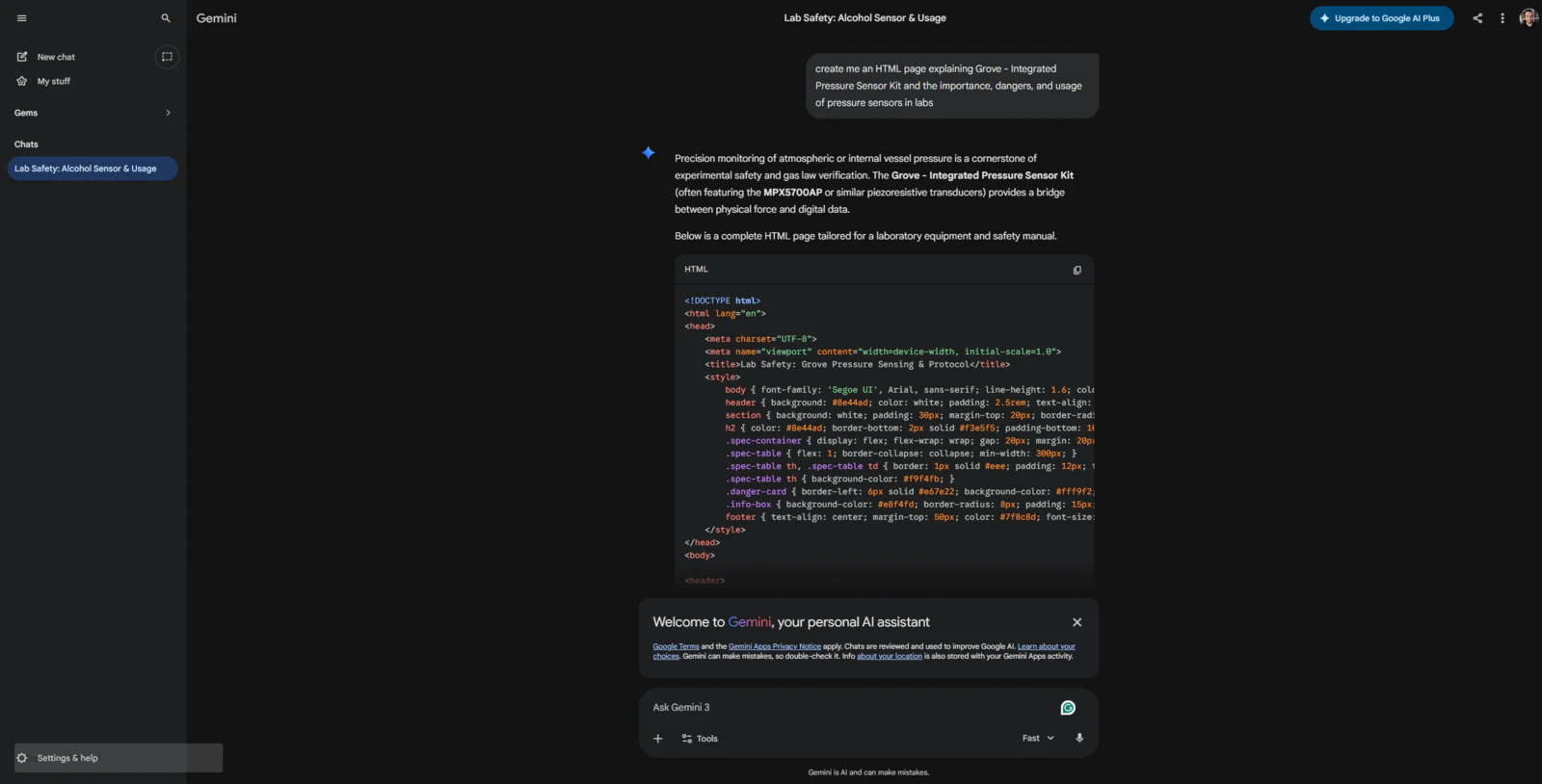
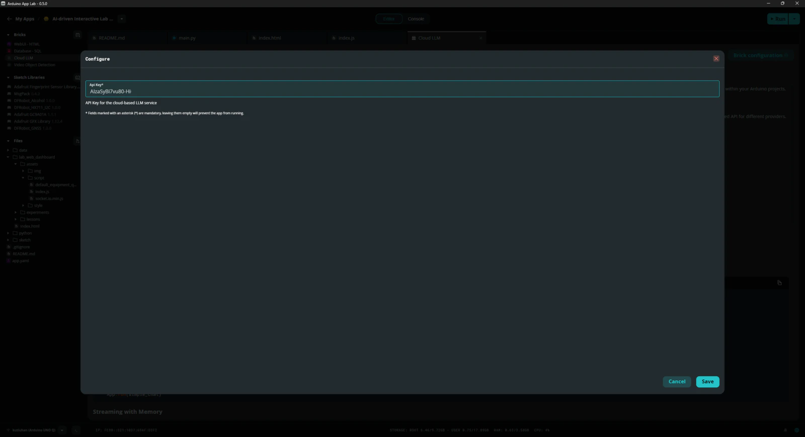
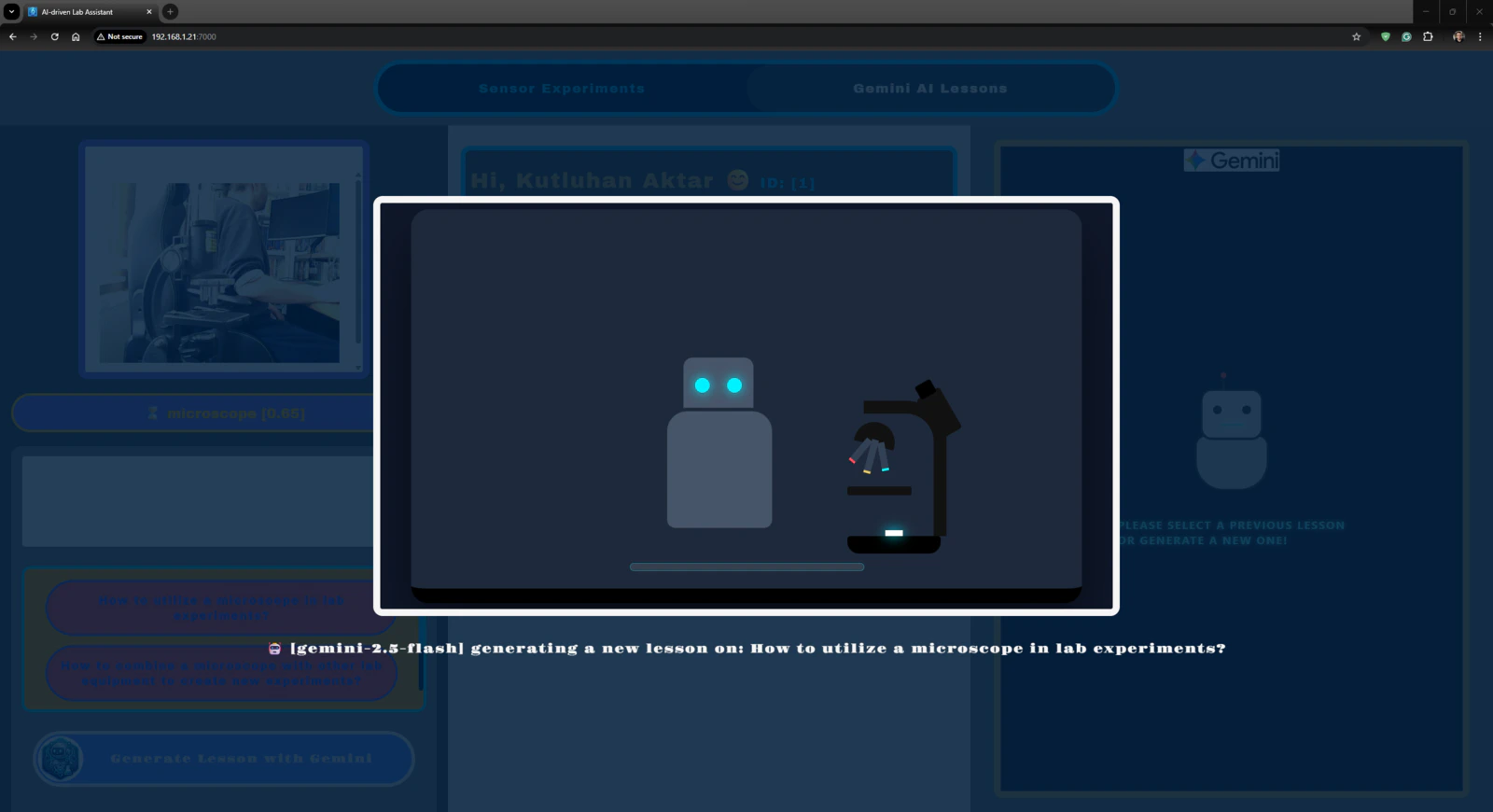
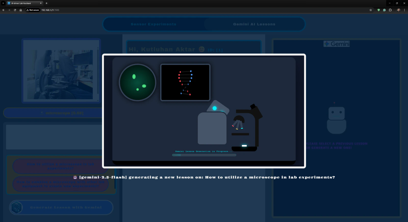
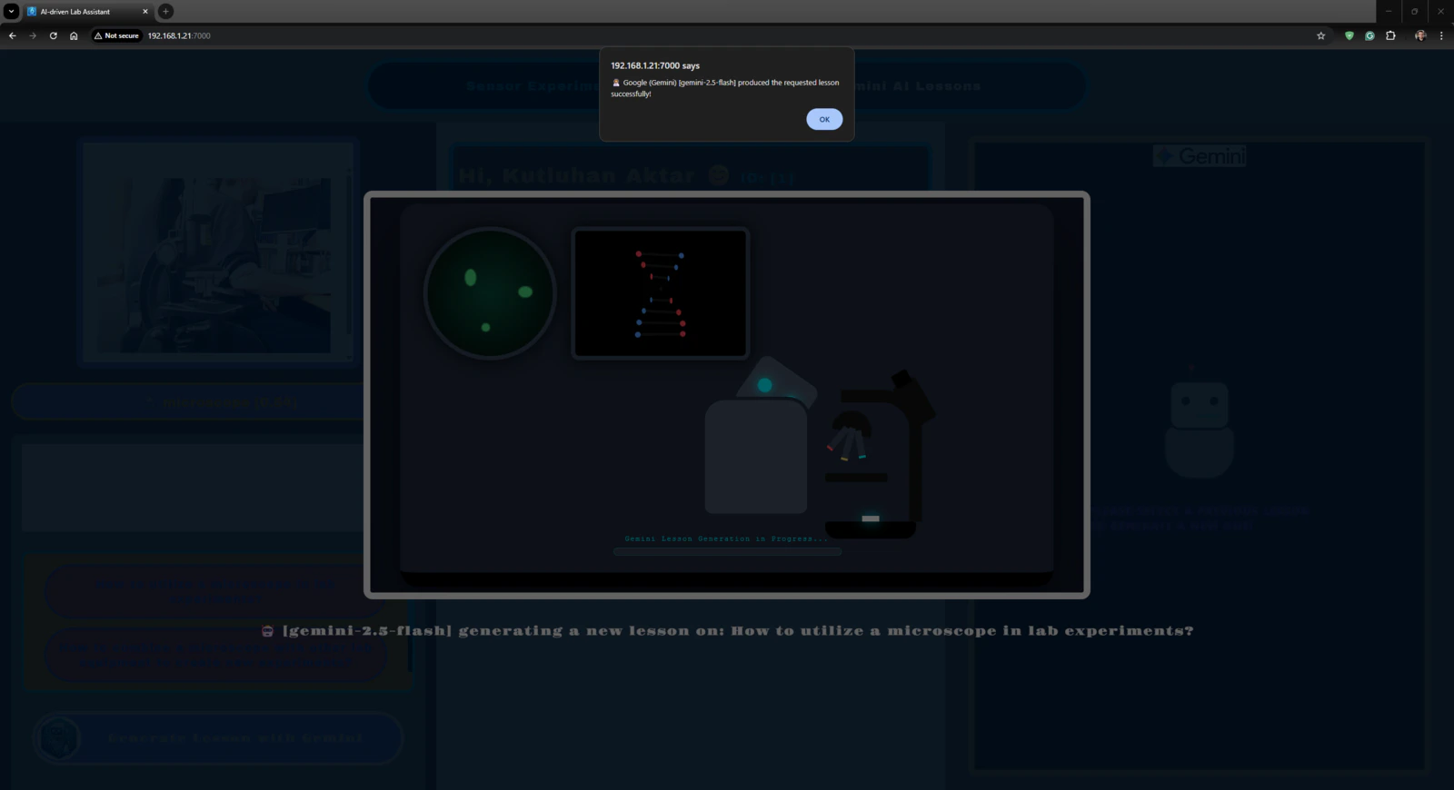
Since I wanted users to generate AI lessons based on questions about specific lab equipment and inspect the LLM-generated lessons via the web dashboard, I decided to fine-tune the large language model responses appropriately to obtain lessons directly in the HTML format. According to my previous experiments with different large language models that I conducted while developing LLM-oriented projects, Google Gemini produced reliable, informative, and concise HTML pages about simple inquiries. Thus, I decided to utilize Google Gemini to enable the ancillary lab assistant to produce AI lessons. Furthermore, Google Gemini has a very low barrier to entry for utilizing its primary chat application and API services. #️⃣ First, to be able to integrate Google Gemini into my Arduino App Lab application, I opened Google AI Studio and created a new API key specific to this project. #️⃣ Since the App Lab already provides a Brick to integrate and use cloud LLMs in Python, I only needed to register the produced API key into my custom application. I will explain how to utilize Bricks in detail in the following steps.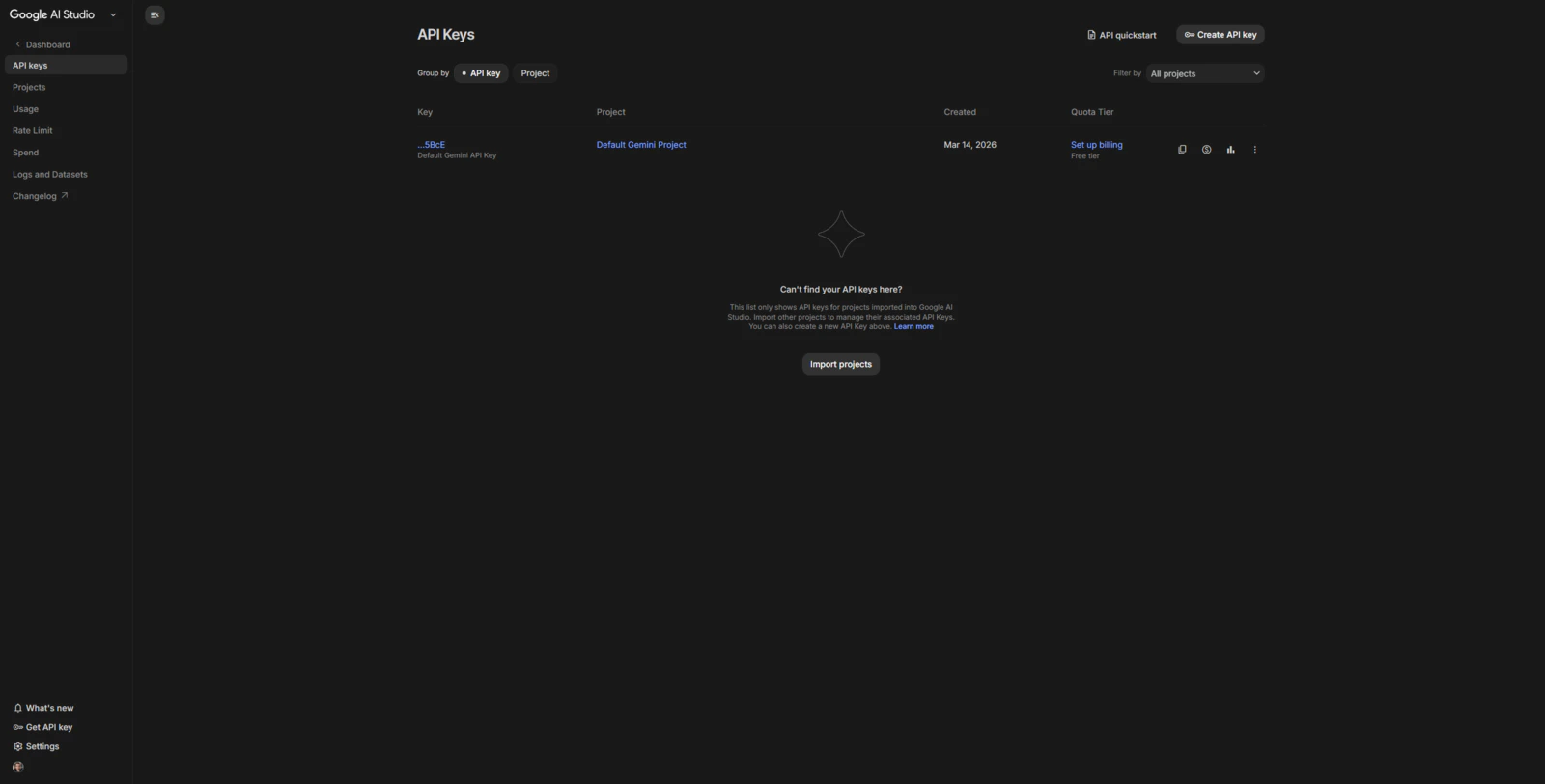
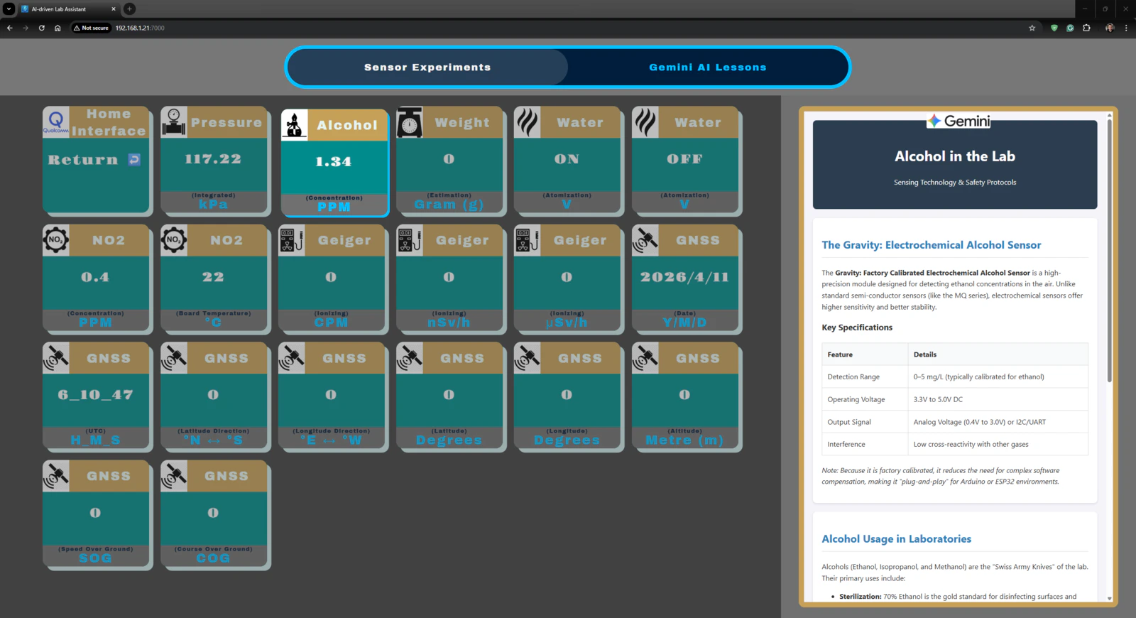
- gemini_alcohol_concentration.html
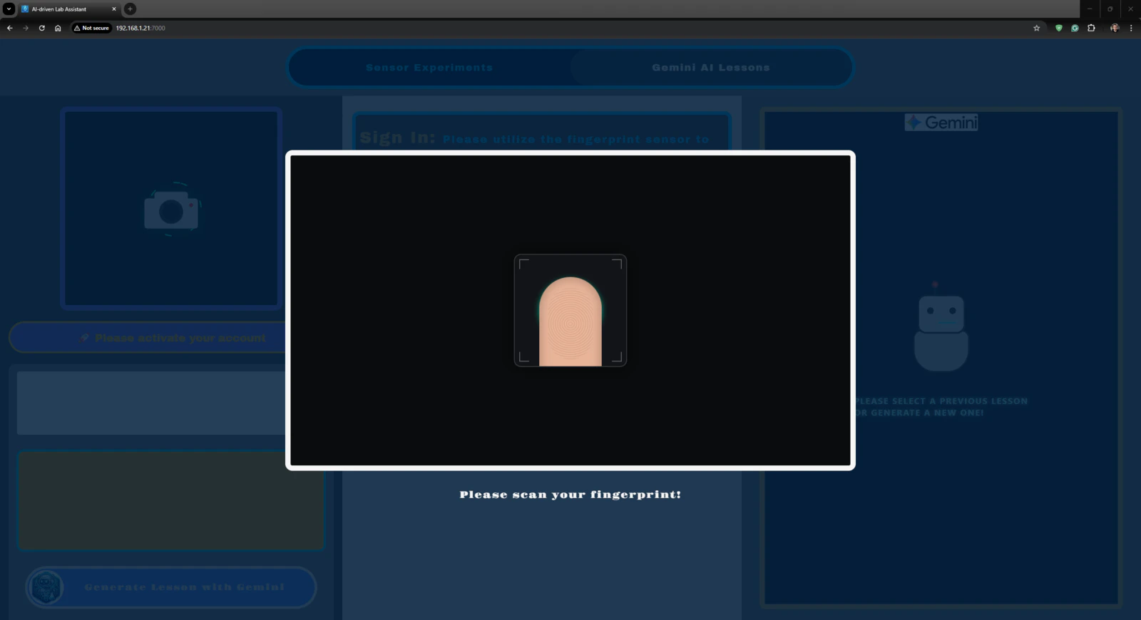
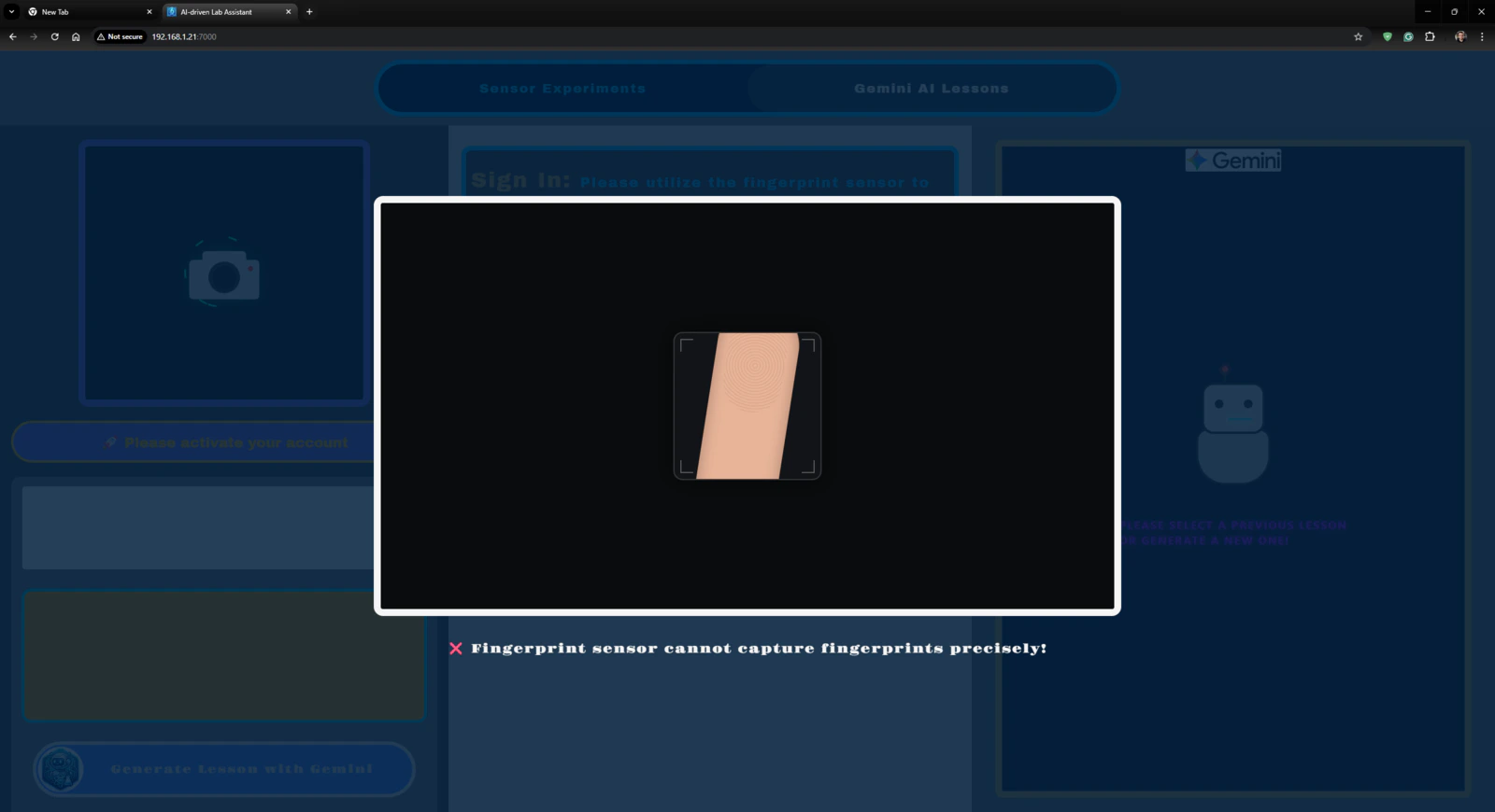
- gemini_fingerprint_waiting.html
- gemini_text_to_speech_stop_logo.png
Step 1: Configuring initial Arduino App Lab settings and determining suitable sensors for the ancillary lab assistant
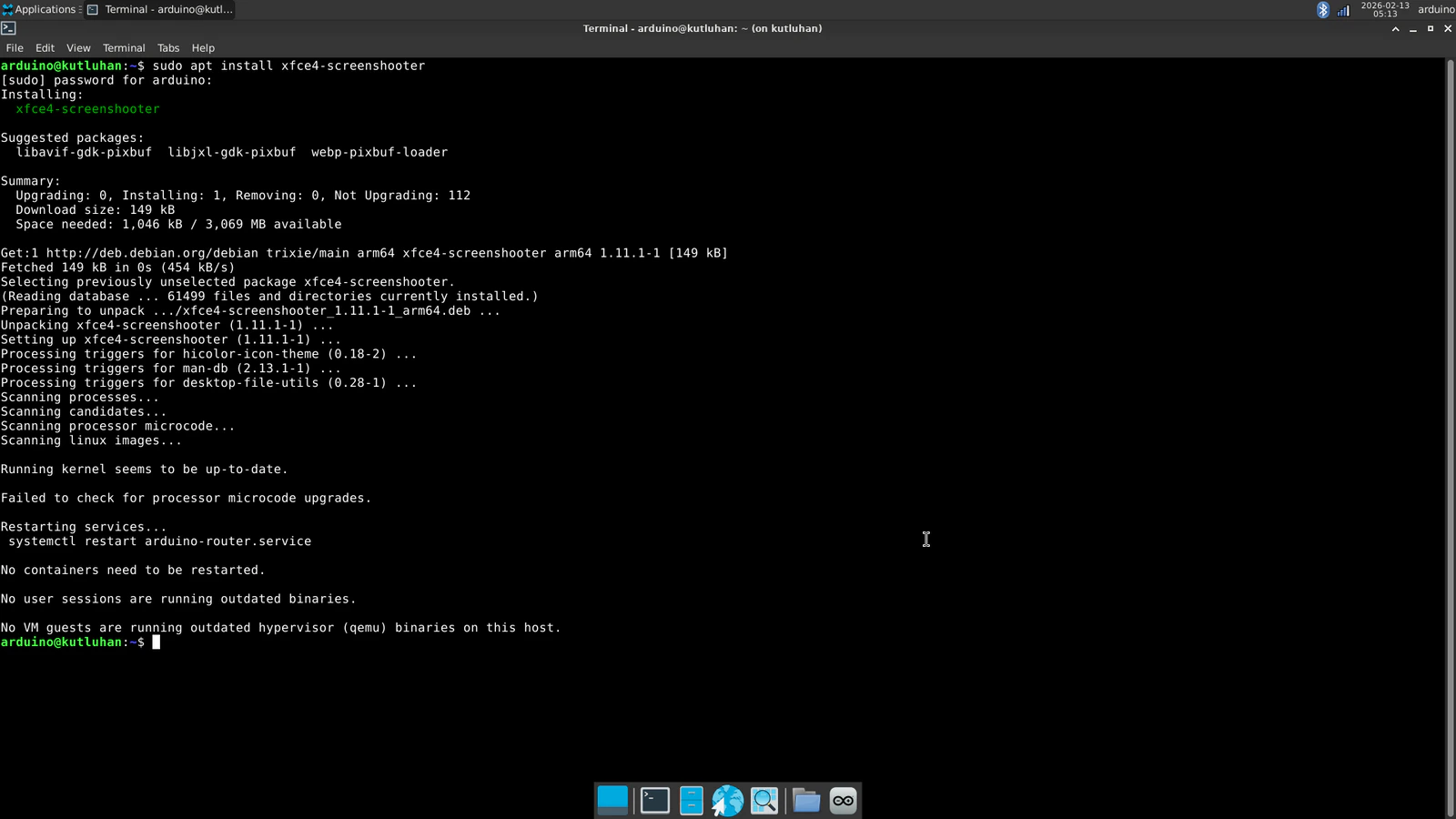
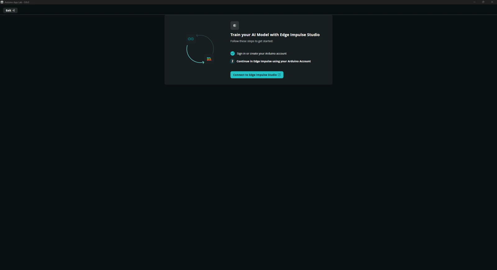
Since Arduino UNO Q comes with the Arduino App Lab installed out of the box, I did not need to take any additional steps to run the App Lab in the SBC mode other than upgrading the Debian Linux operating system and the App Lab to their latest versions. However, to be able to utilize the network mode to program the lab assistant App Lab application remotely, I downloaded the Arduino App Lab on my workstation. #️⃣ First, I connected a compatible USB dongle (hub), UGREEN 5-in-1, to the UNO Q in order to upgrade the Debian operating system and the Arduino App Lab.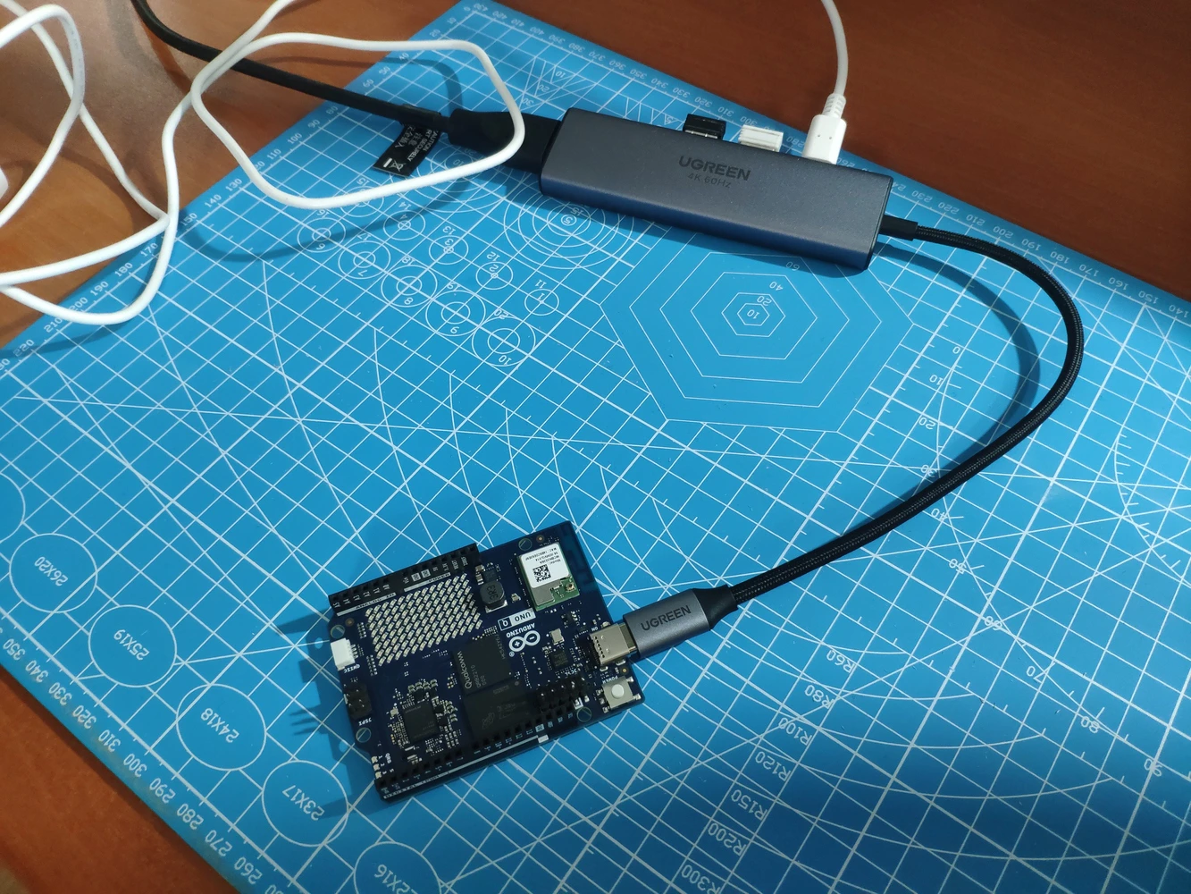

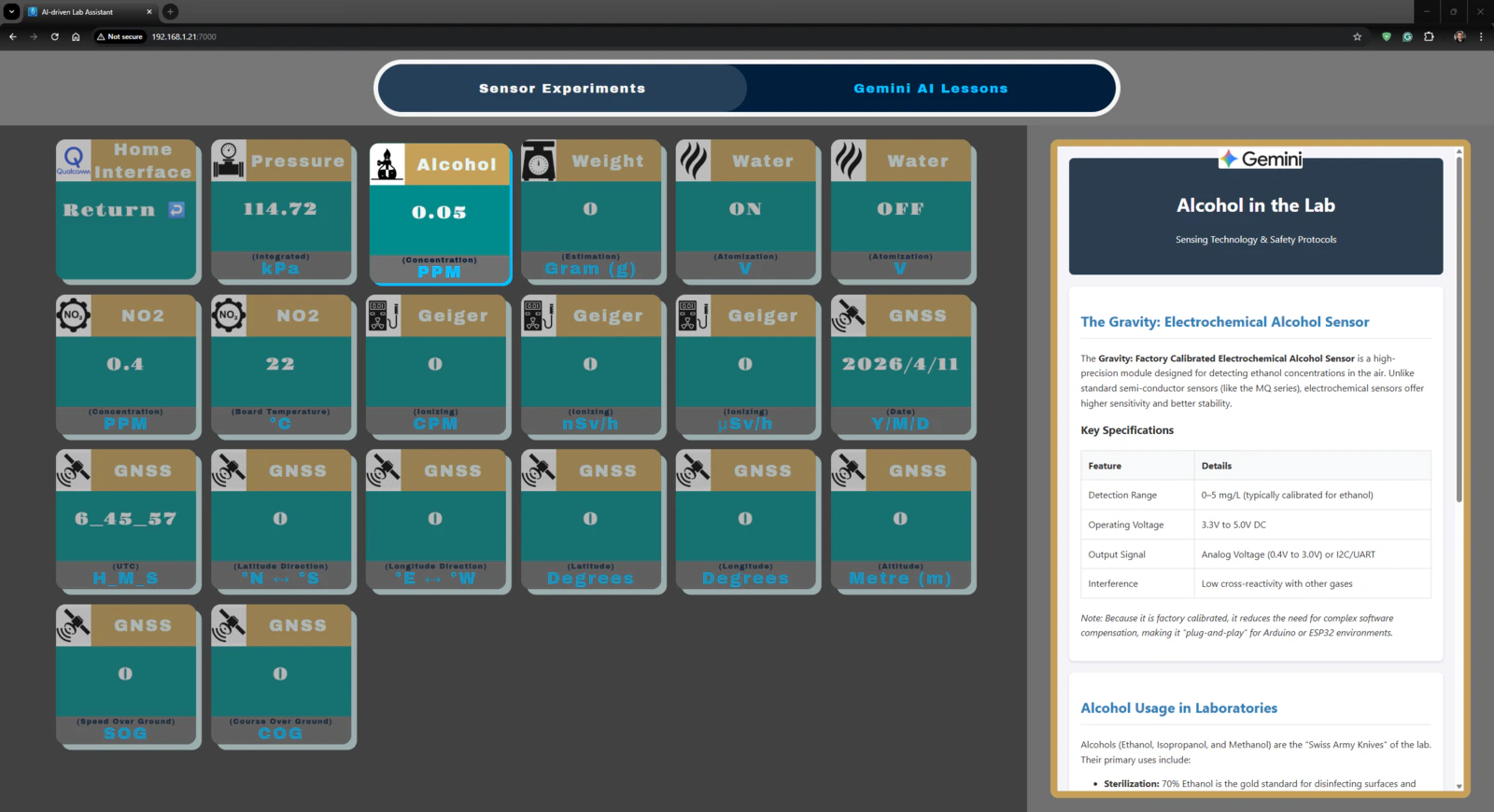
- Gravity: Electrochemical Alcohol Sensor | Guide
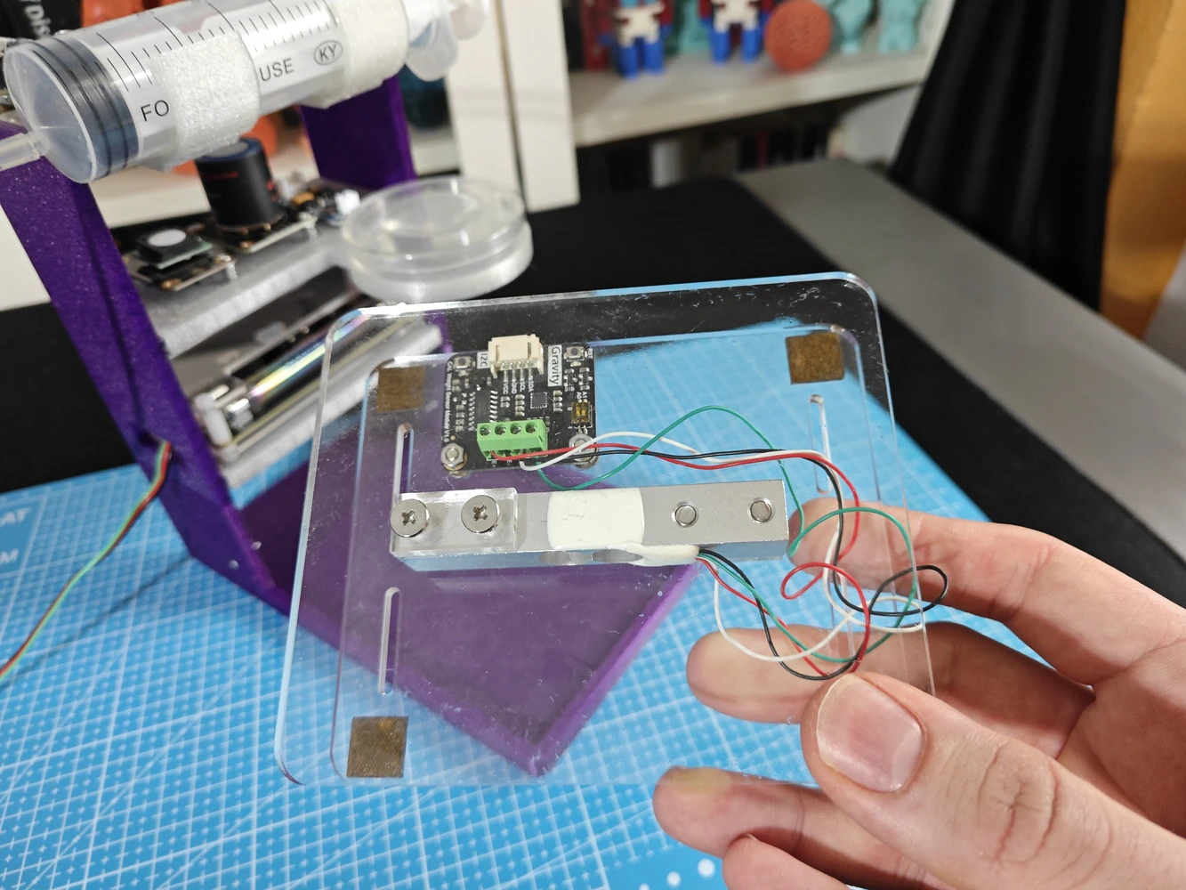
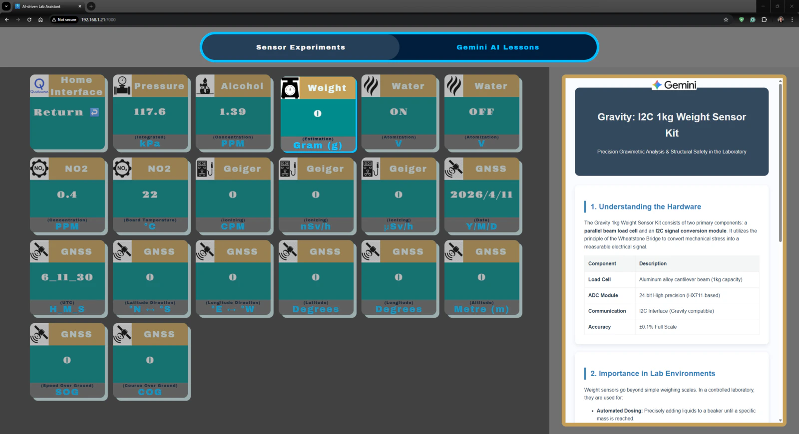
- Gravity: 1Kg Weight Sensor Kit - HX711 | Guide
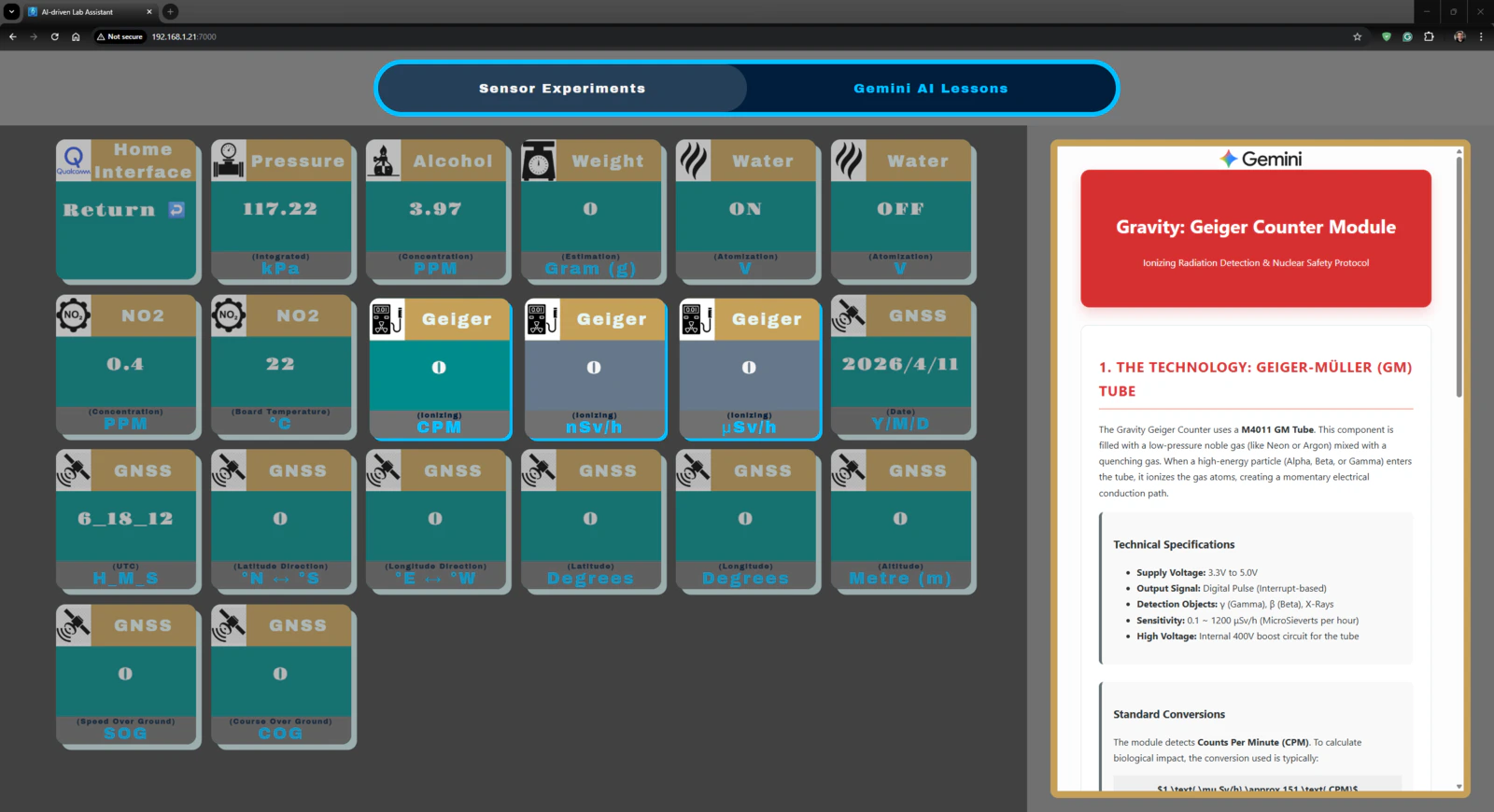
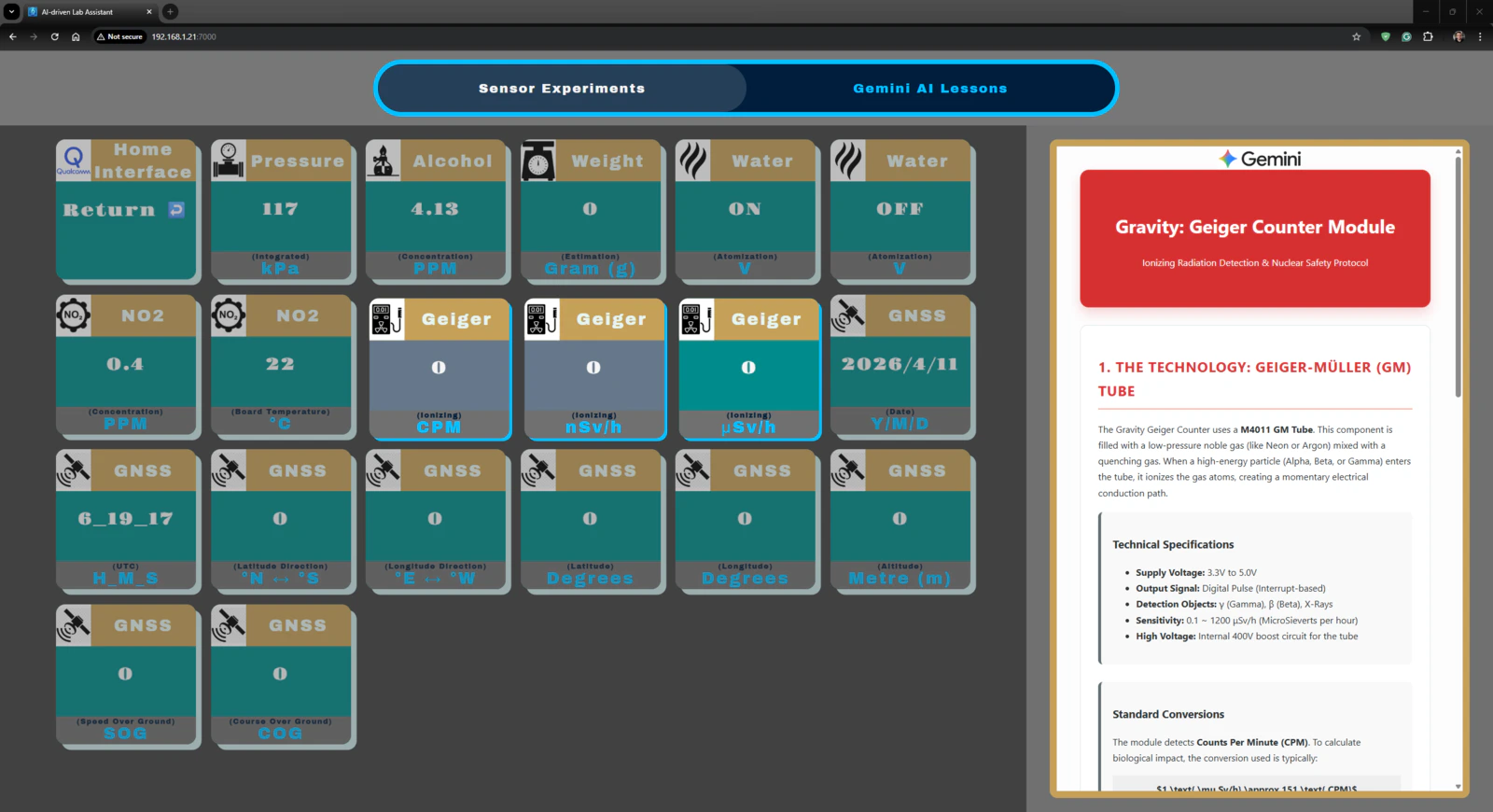
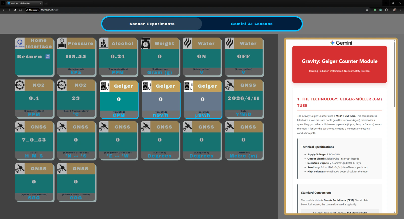
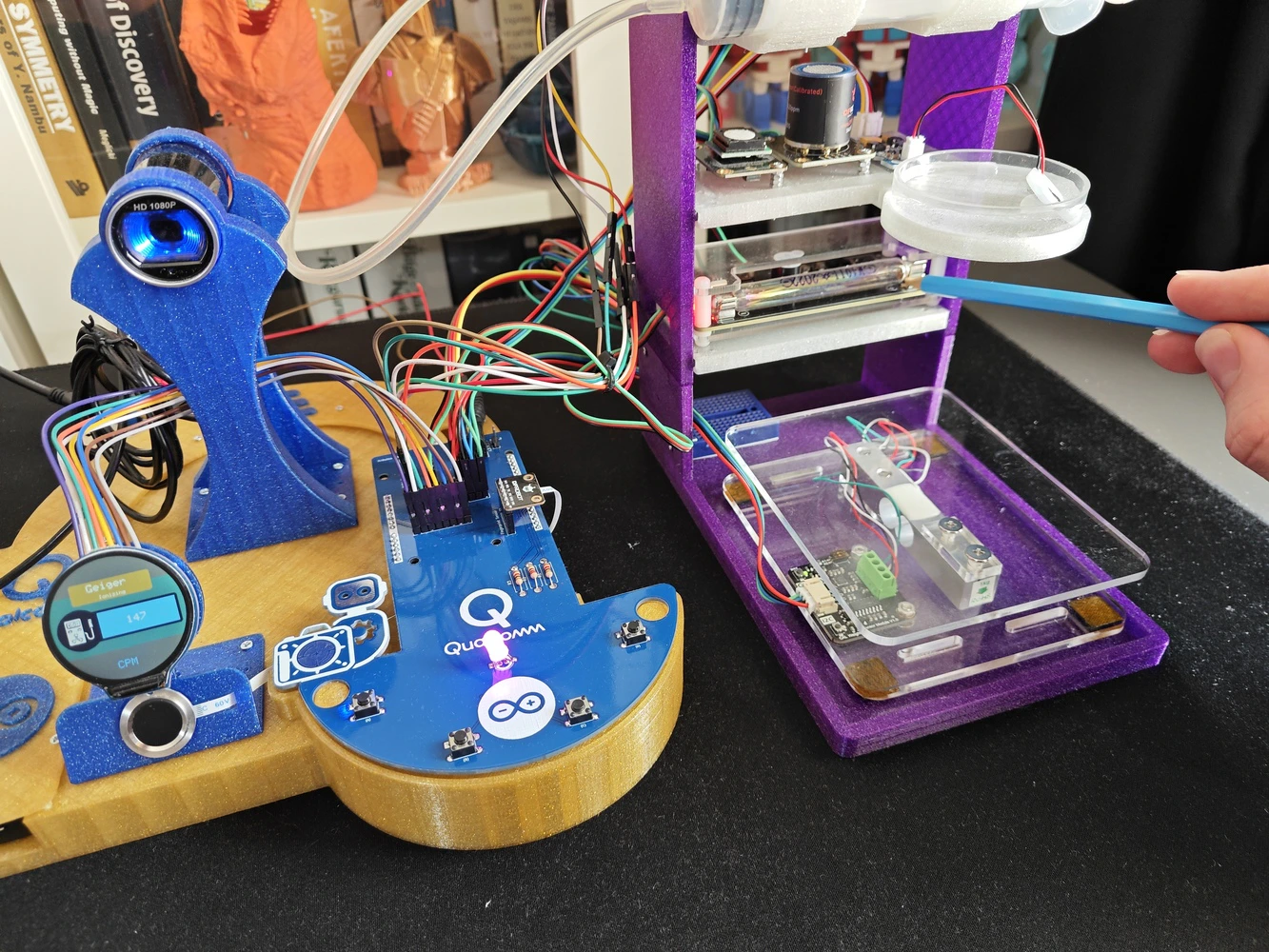
- Gravity: Geiger Counter Module | Guide
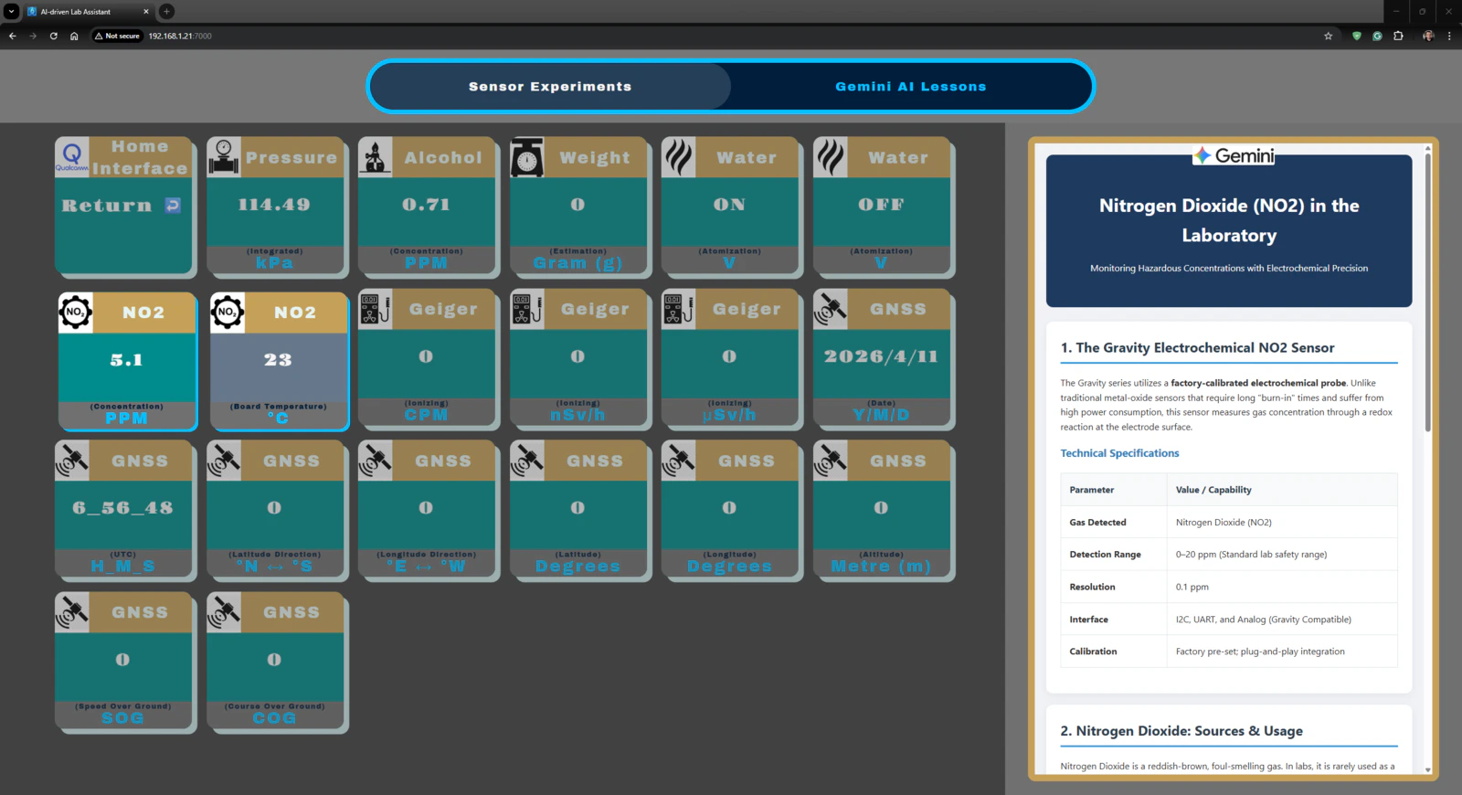
- Gravity: Electrochemical Nitrogen Dioxide Sensor | Guide
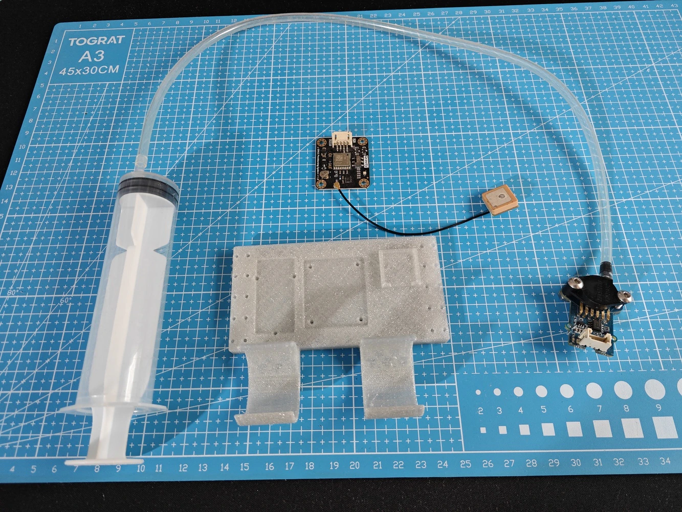
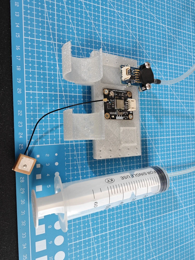
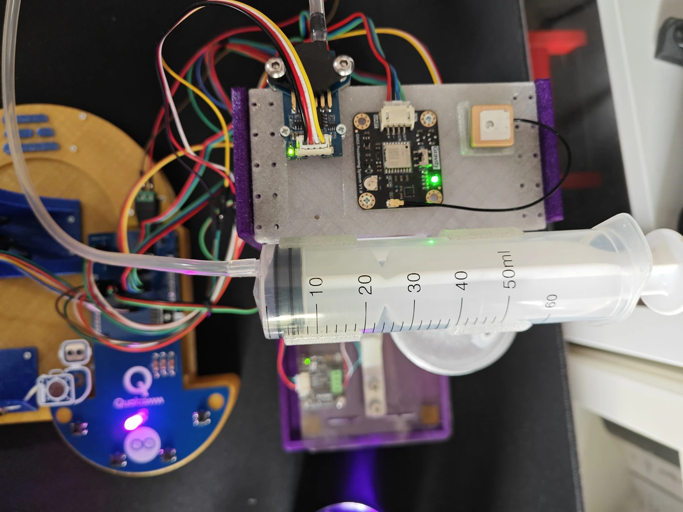
- Grove: Integrated Pressure Sensor Kit (MPX5700AP) | Guide
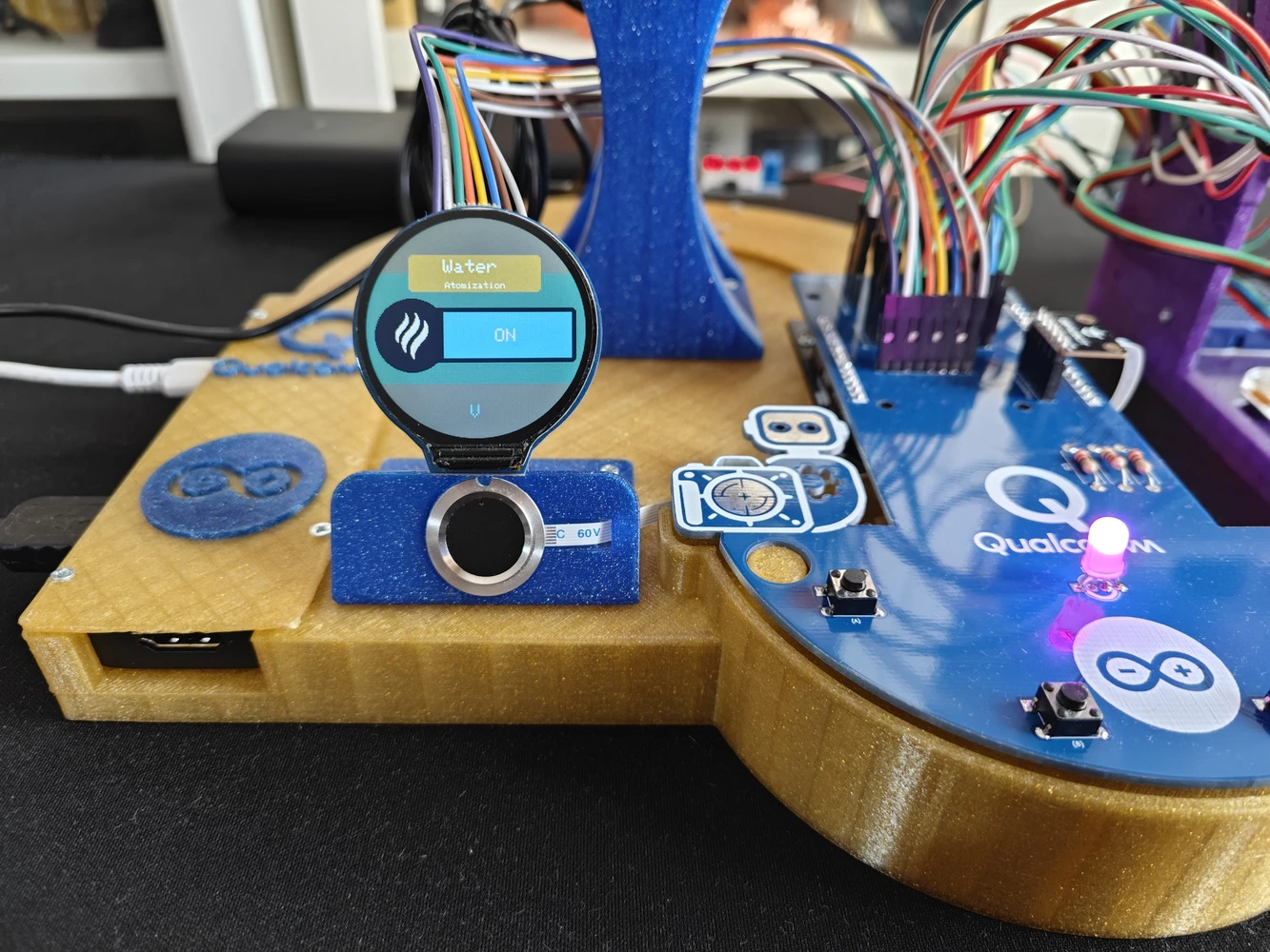
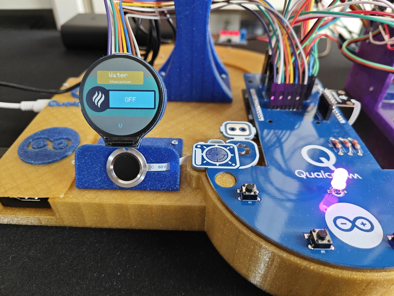
- Grove: Water Atomization Sensor (Ultrasonic) | Guide
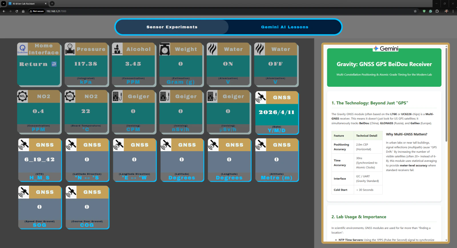
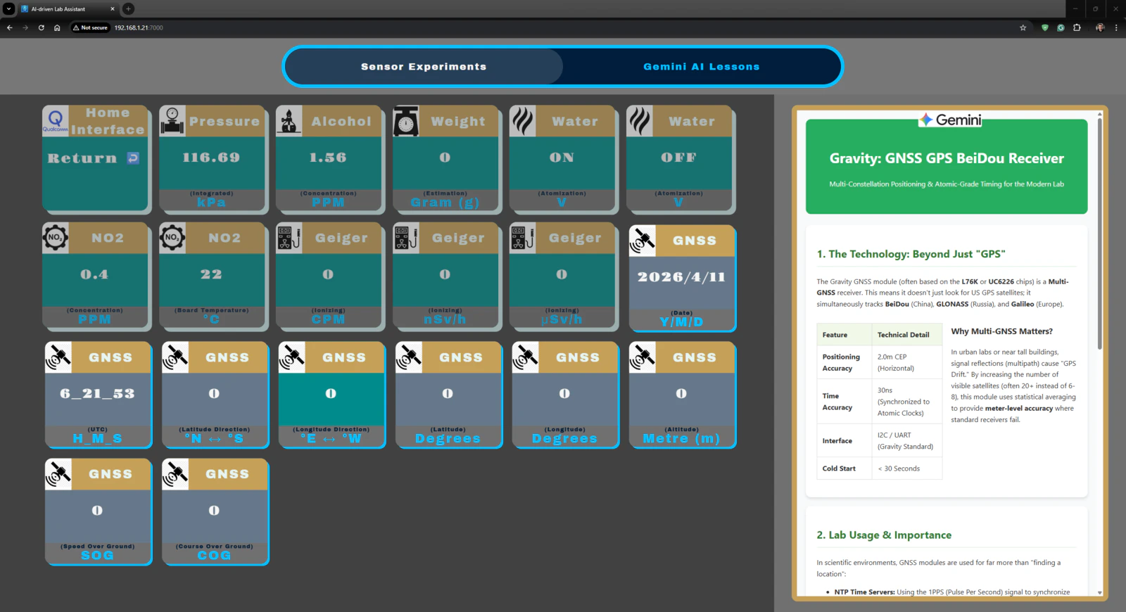
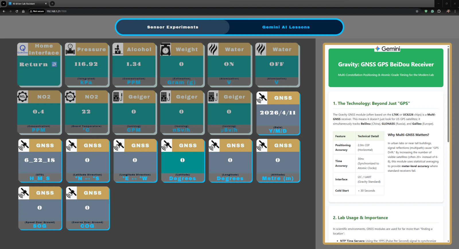
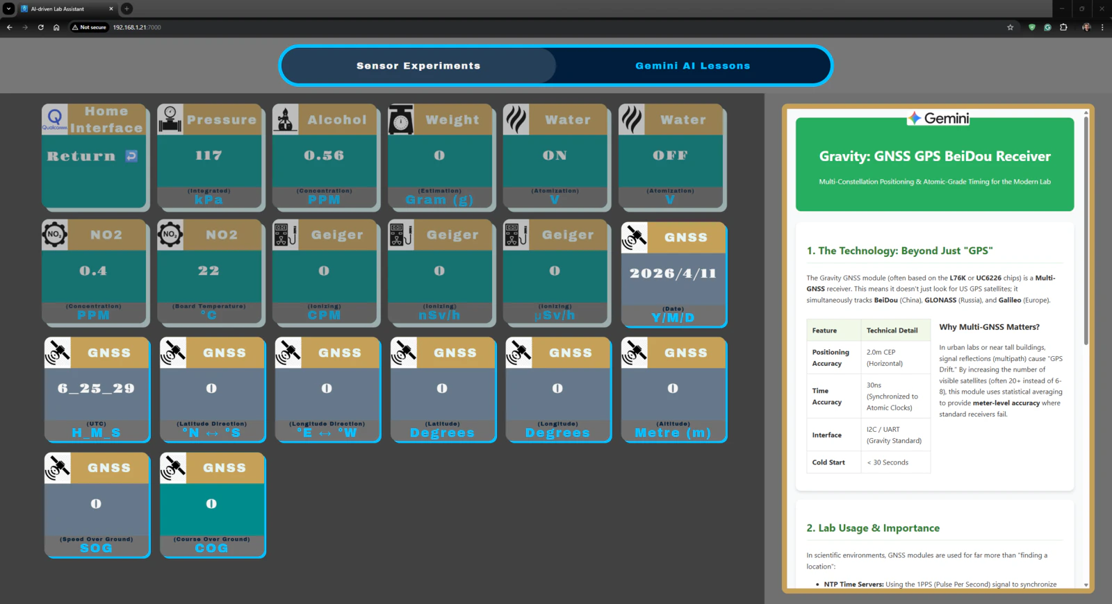
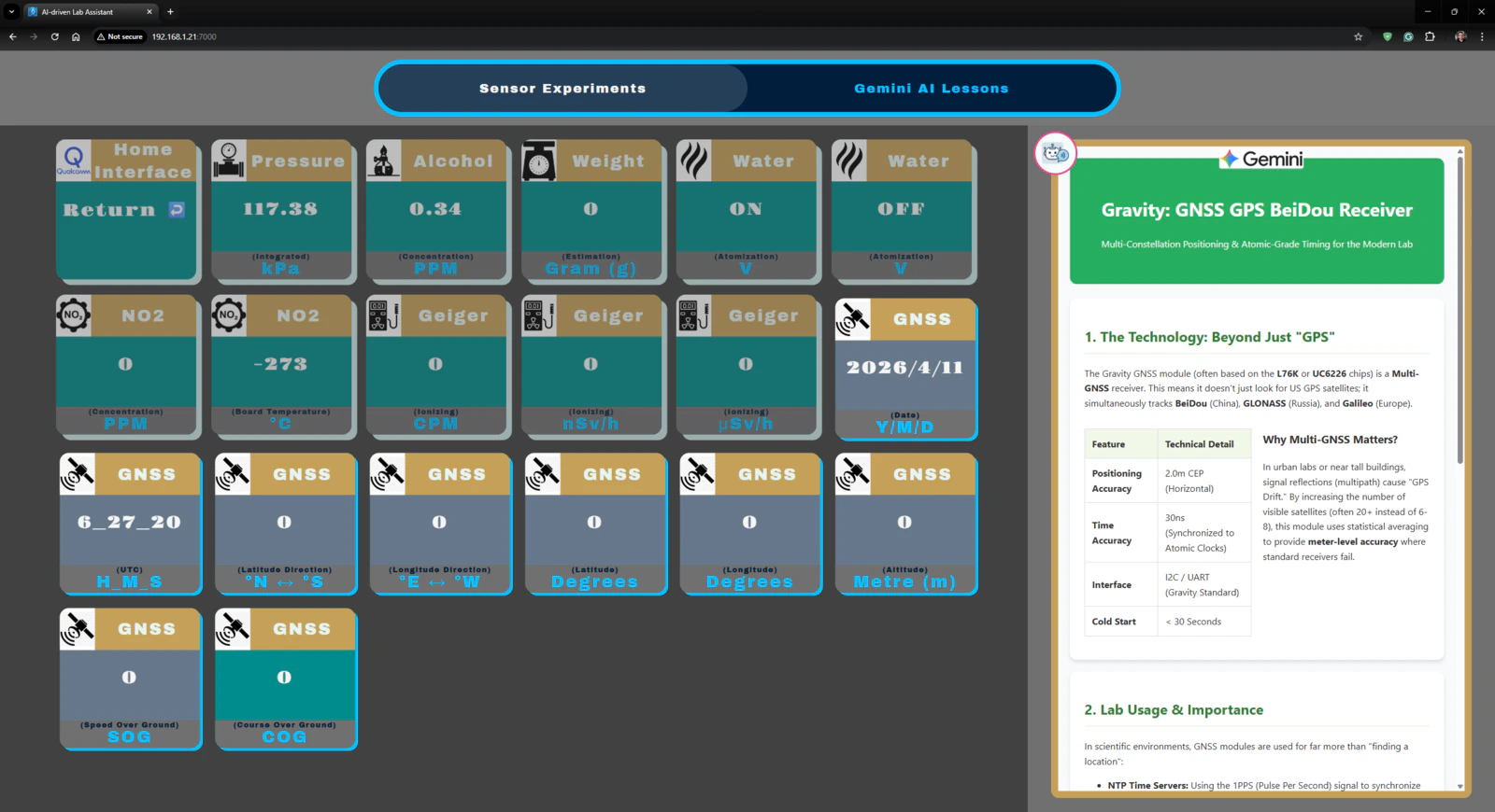
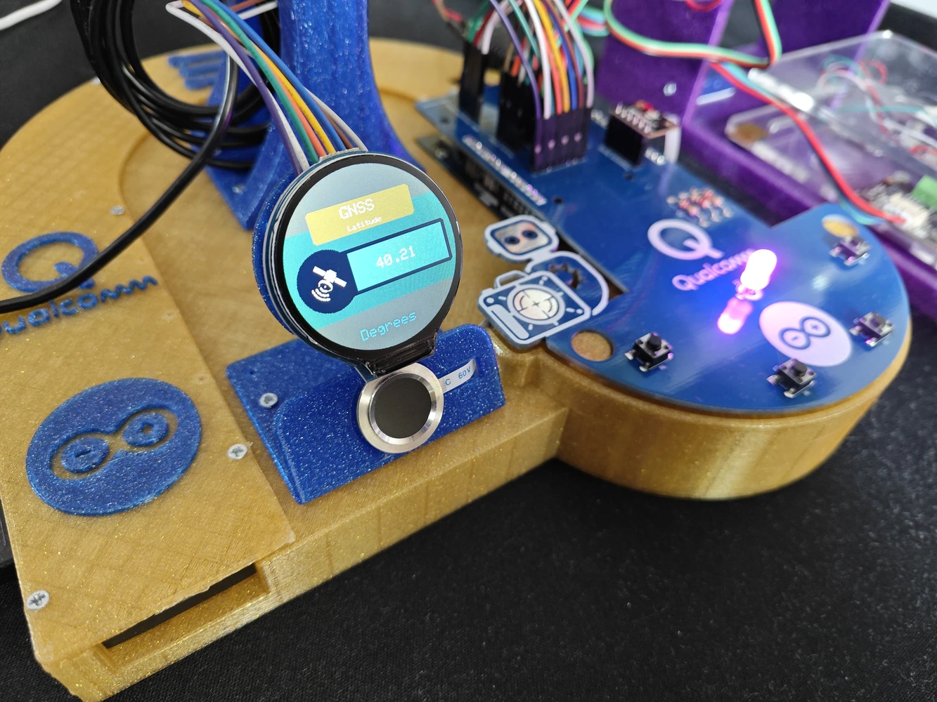
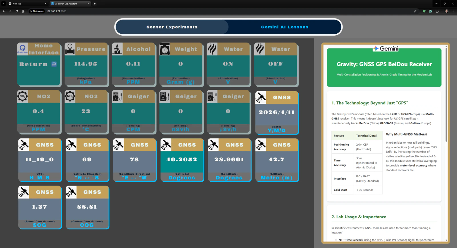
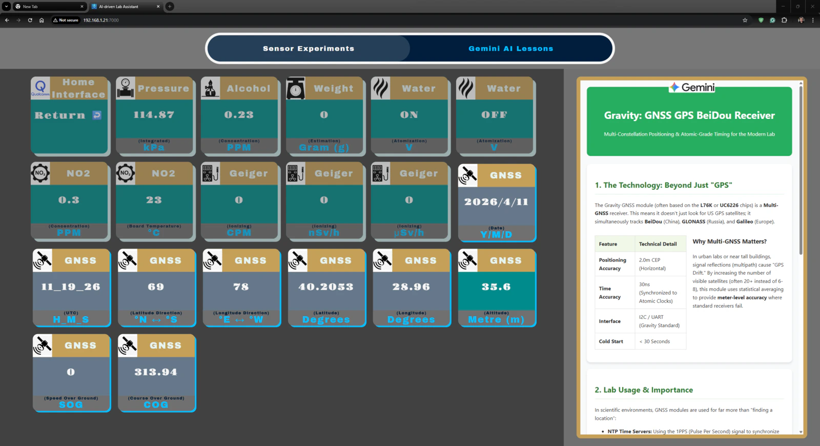
- Gravity: GNSS Positioning Module | Guide
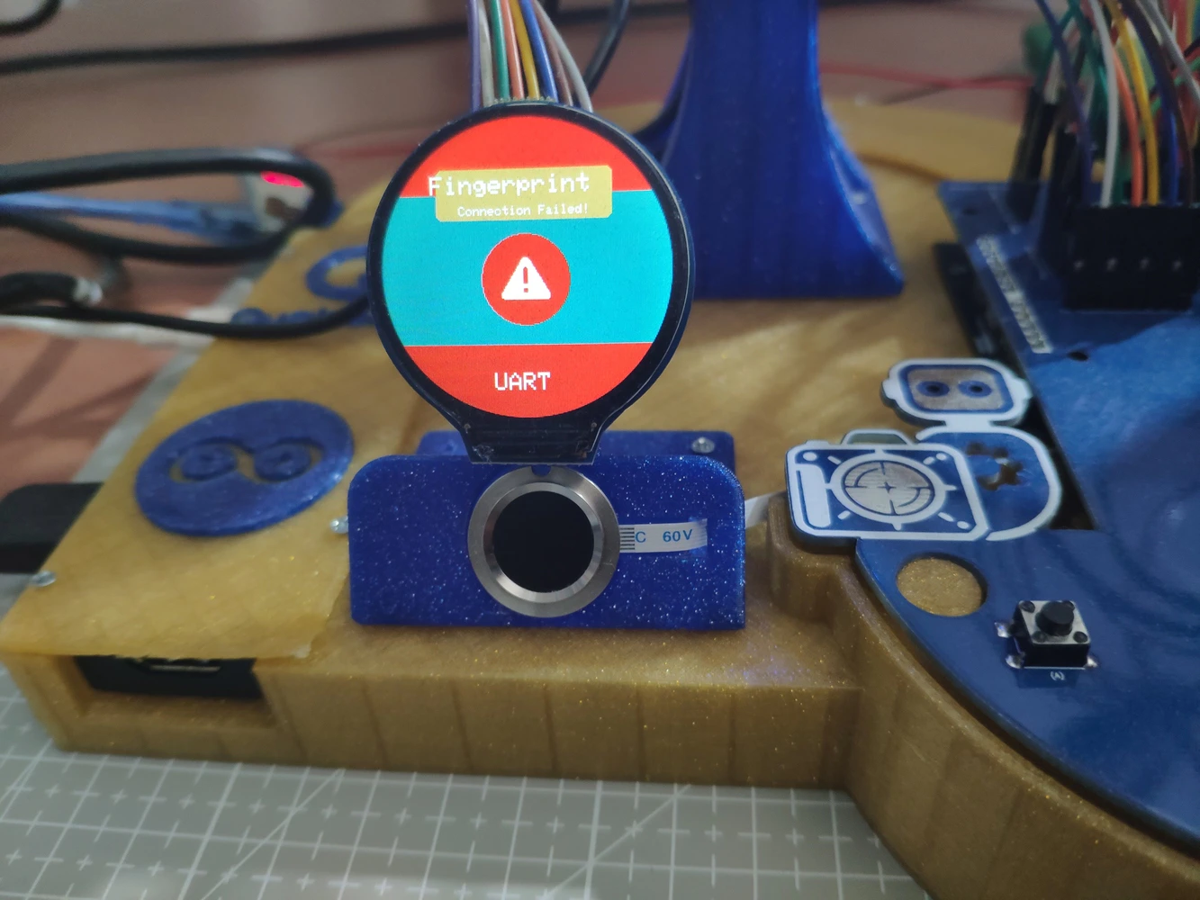
- DFRobot Capacitive Fingerprint Sensor (UART) | Guide
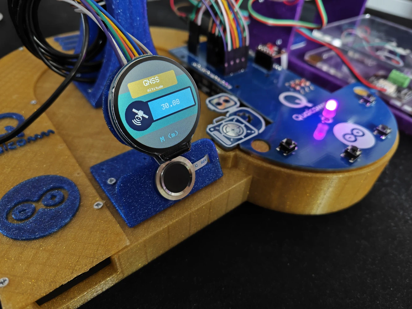
- Waveshare 1.28” Round LCD Display Module (GC9A01) | Guide
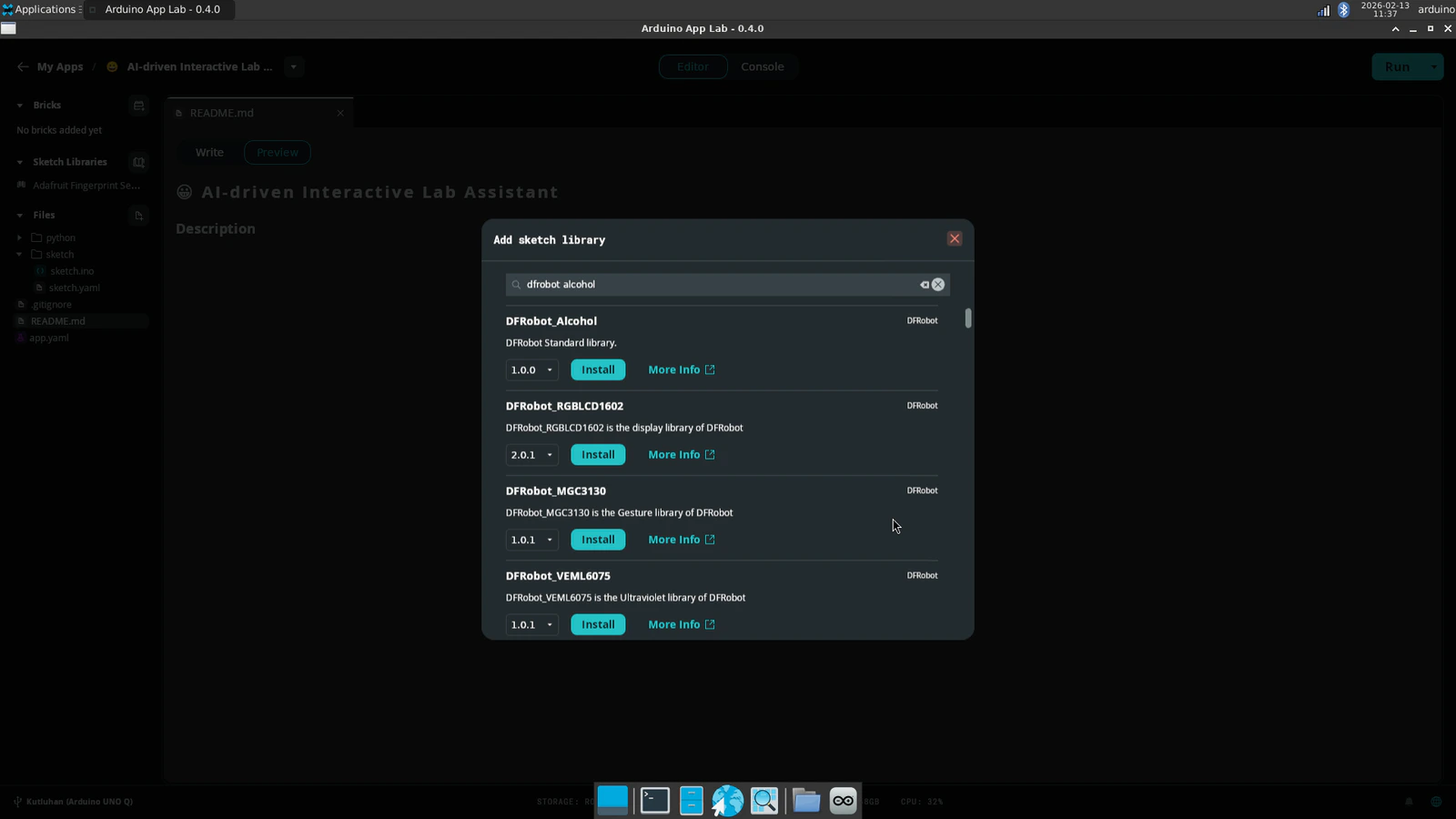
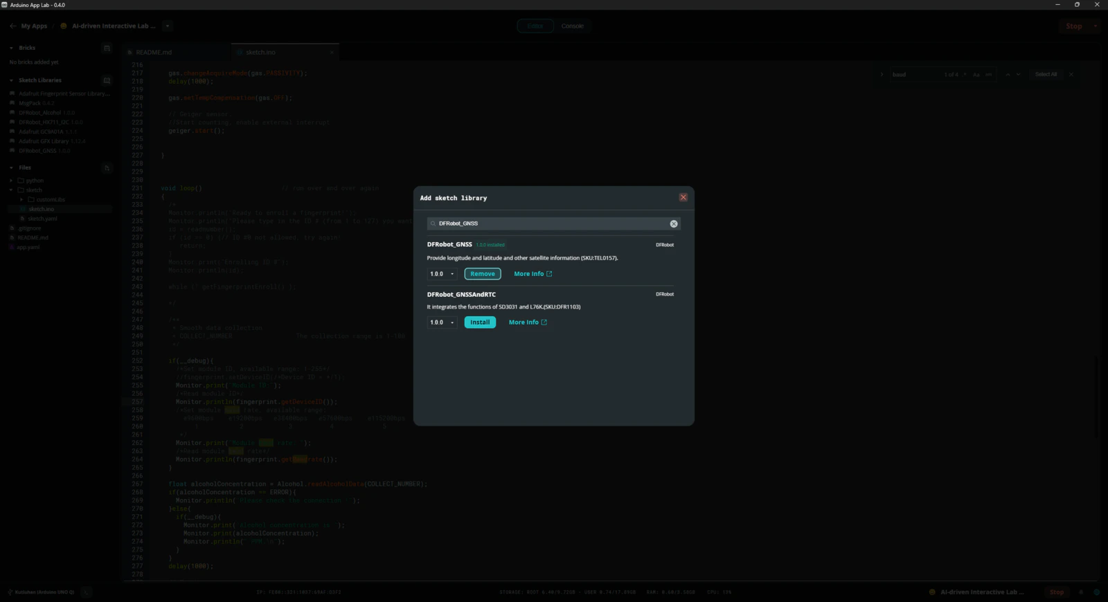
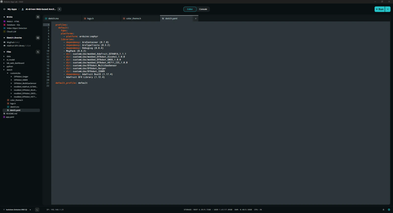
Step 1.1: Adding and revising the sketch libraries to make the target sensors compatible with the UNO Q
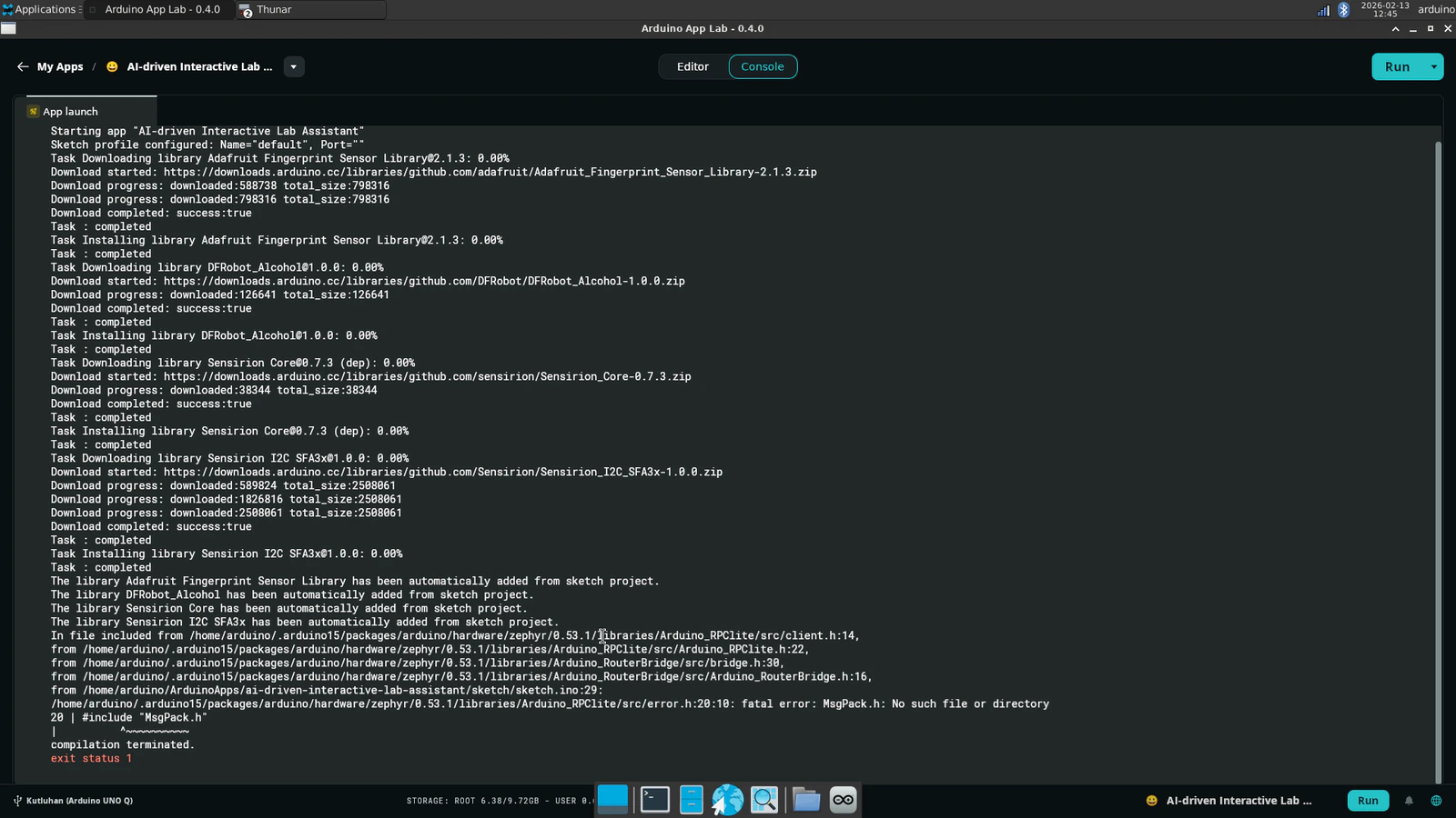
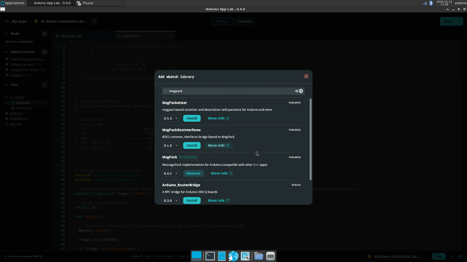
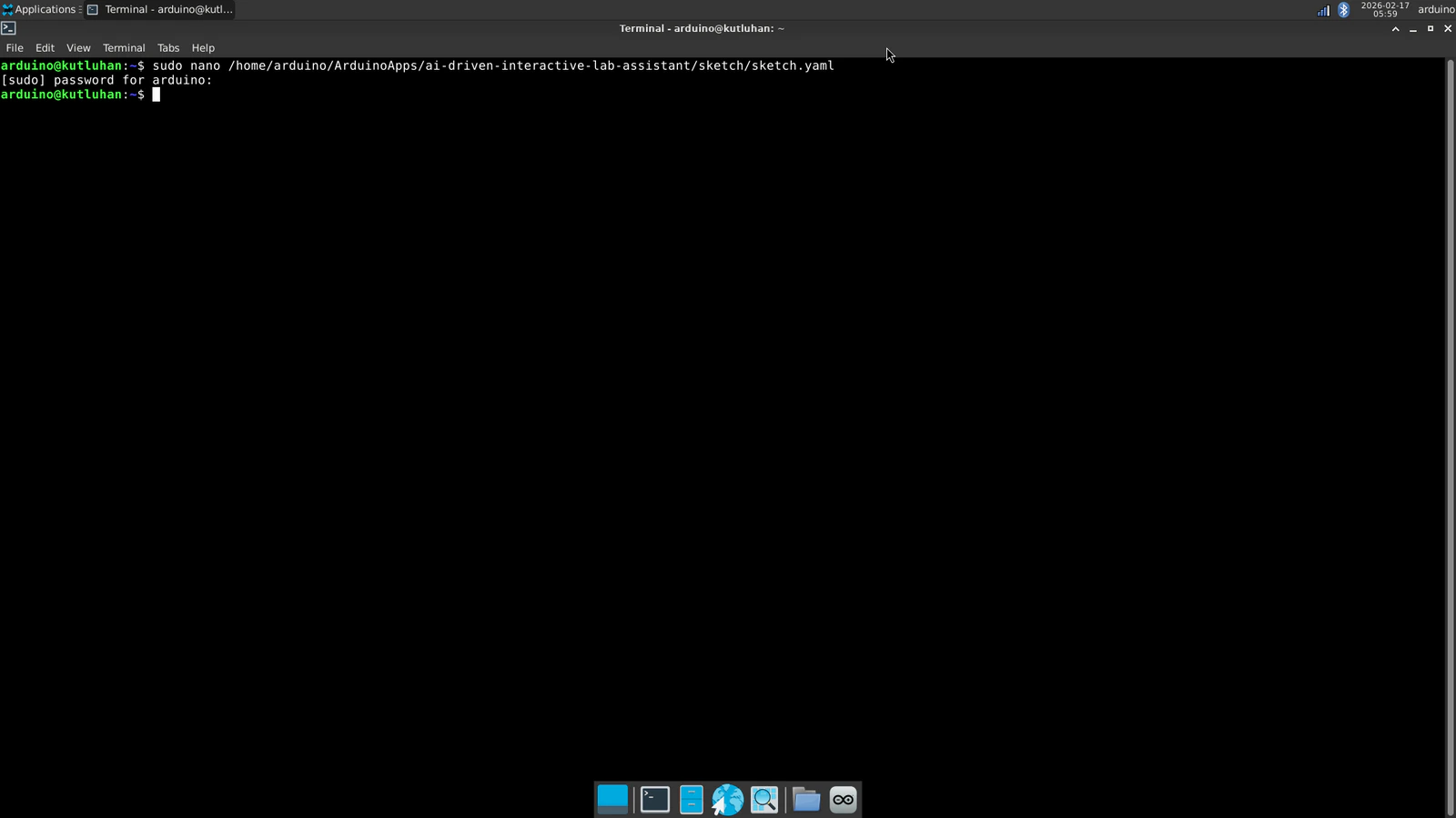
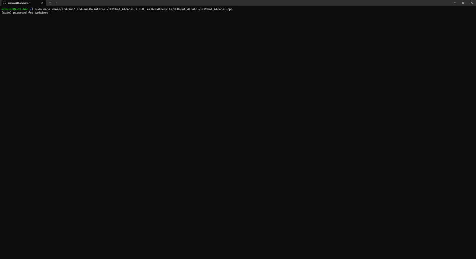
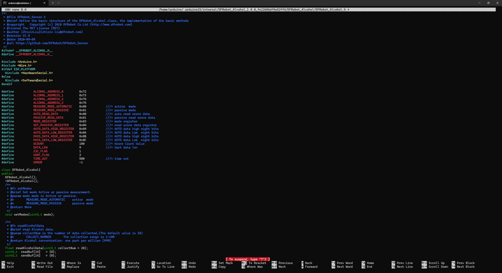
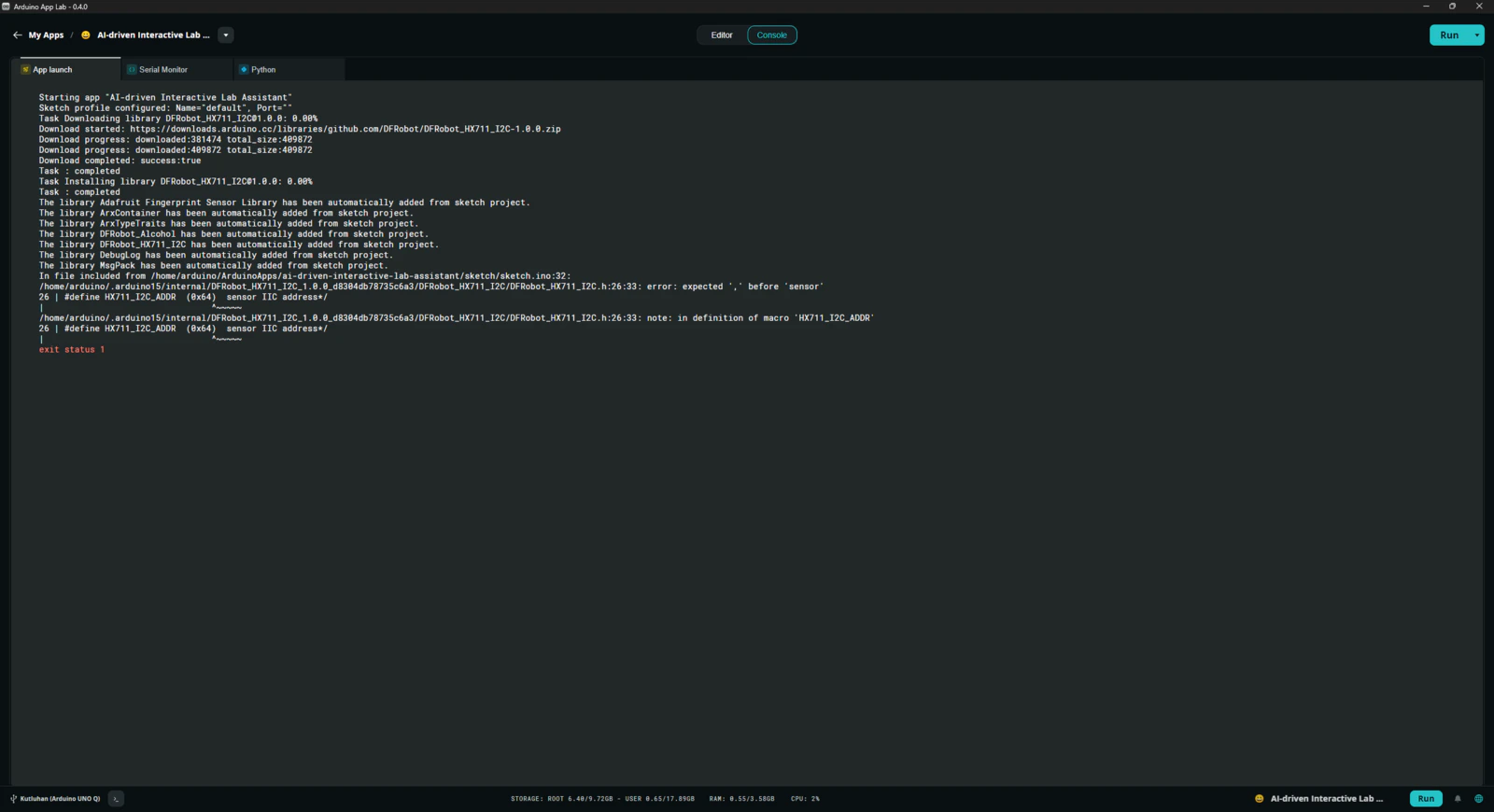
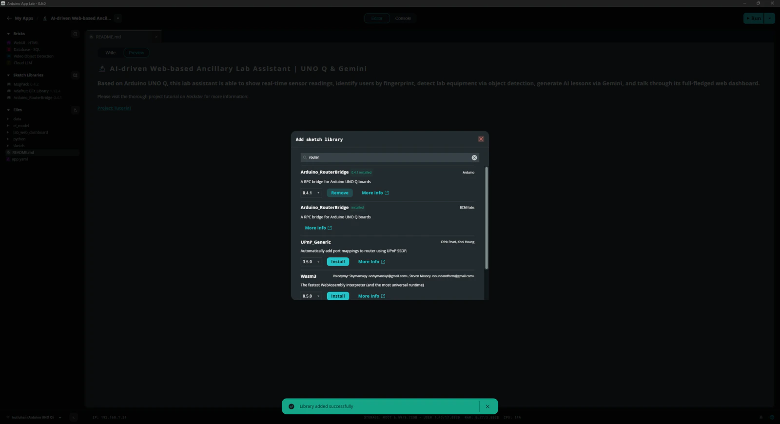
Even though Arduino UNO Q shares the same layout with the standard Arduino Uno, the MCU structure (STM32) and the bootloader (which runs on the Zephyr RTOS) are completely different. Thus, I needed to add component libraries that were not present in the provided App Lab library collection and heavily modify most of the component libraries to make them compatible with the UNO Q structure. #️⃣ First, I added sketch libraries available in the provided App Lab library collection, including the MessagePack (msgpack) library, which is essential to utilize the Arduino Router service on the MCU.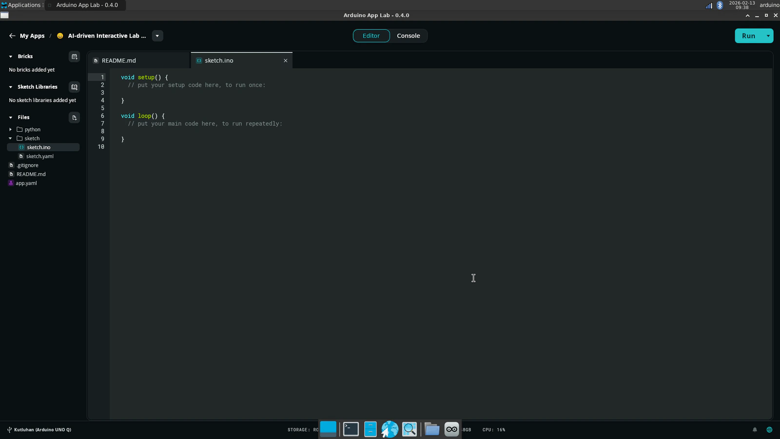
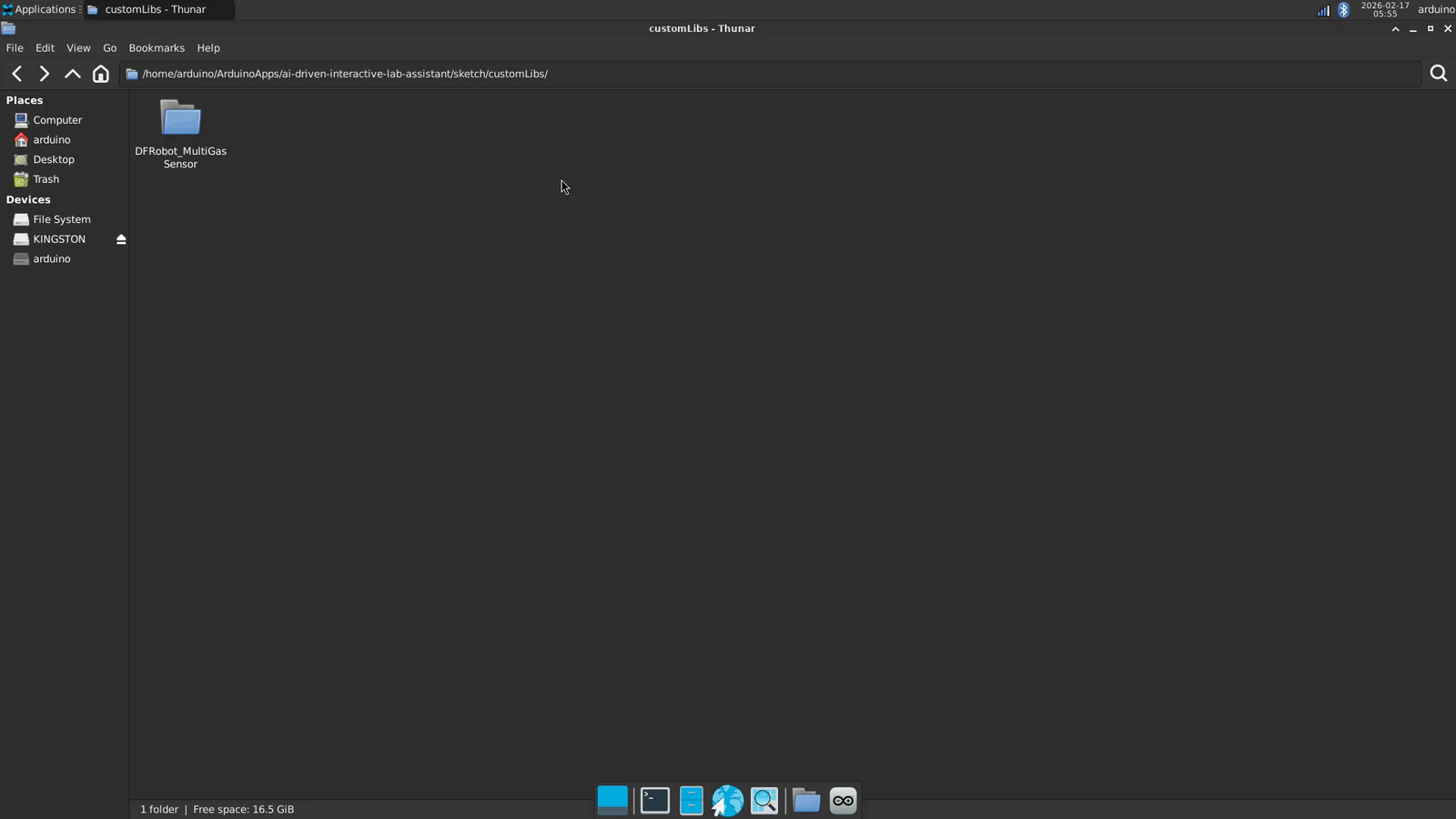
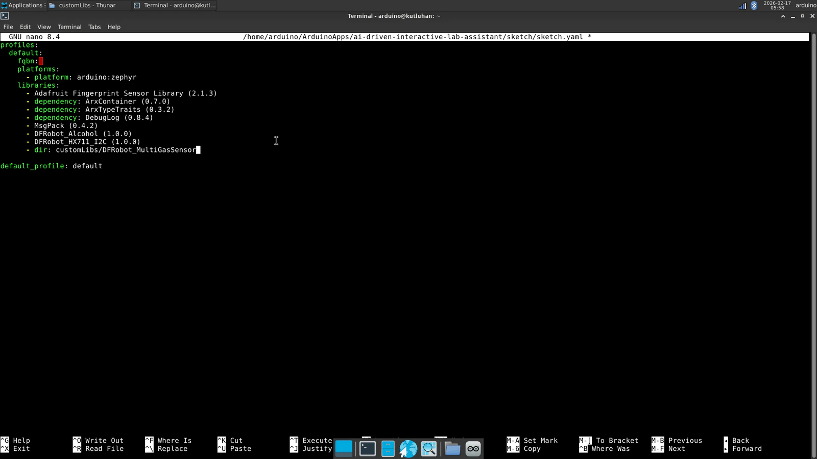
- dir: customLibs/<lib_name>
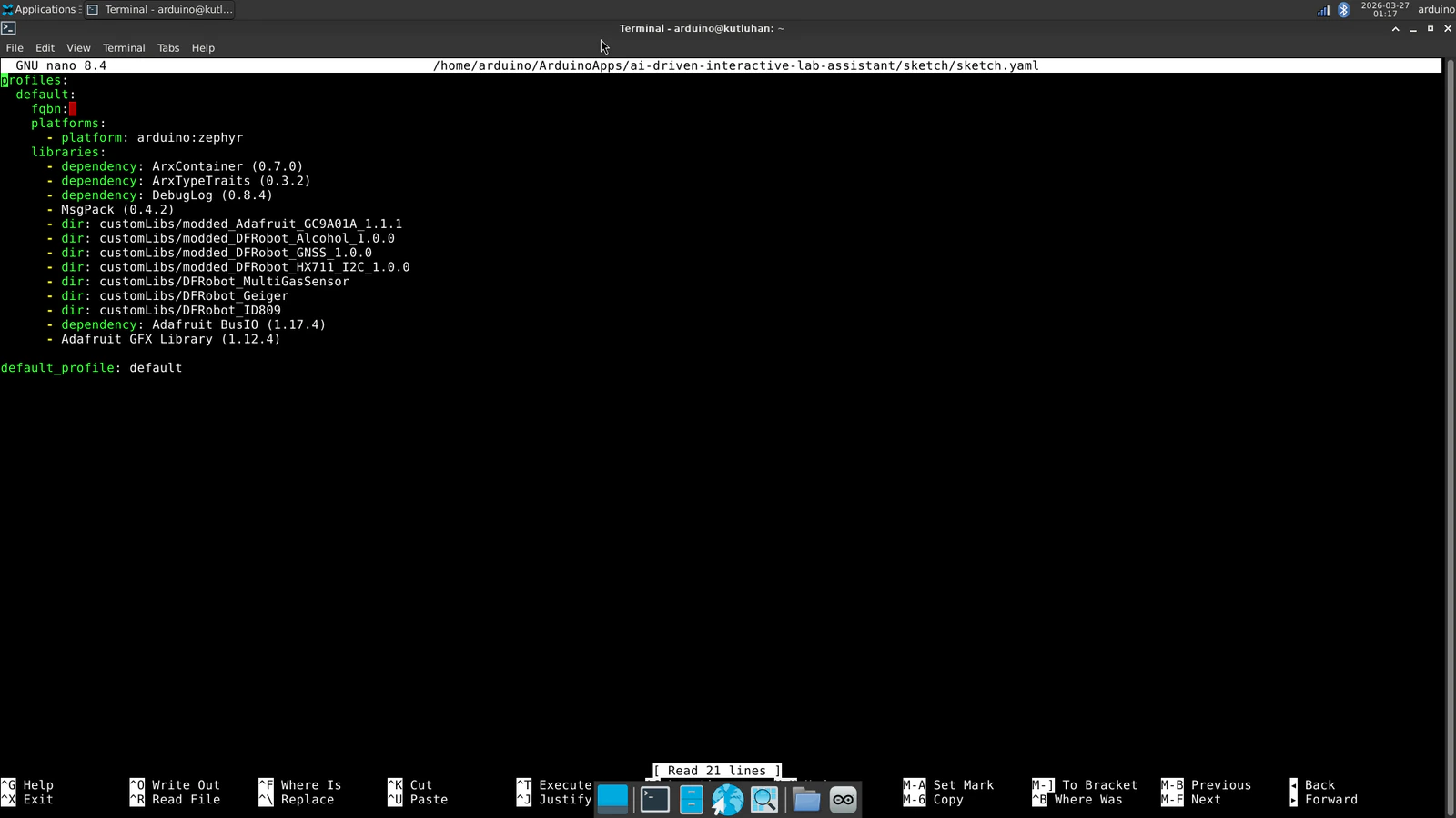
- dir: customLibs/DFRobot_MultiGasSensor
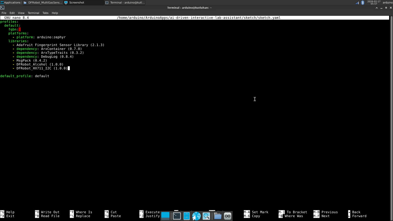

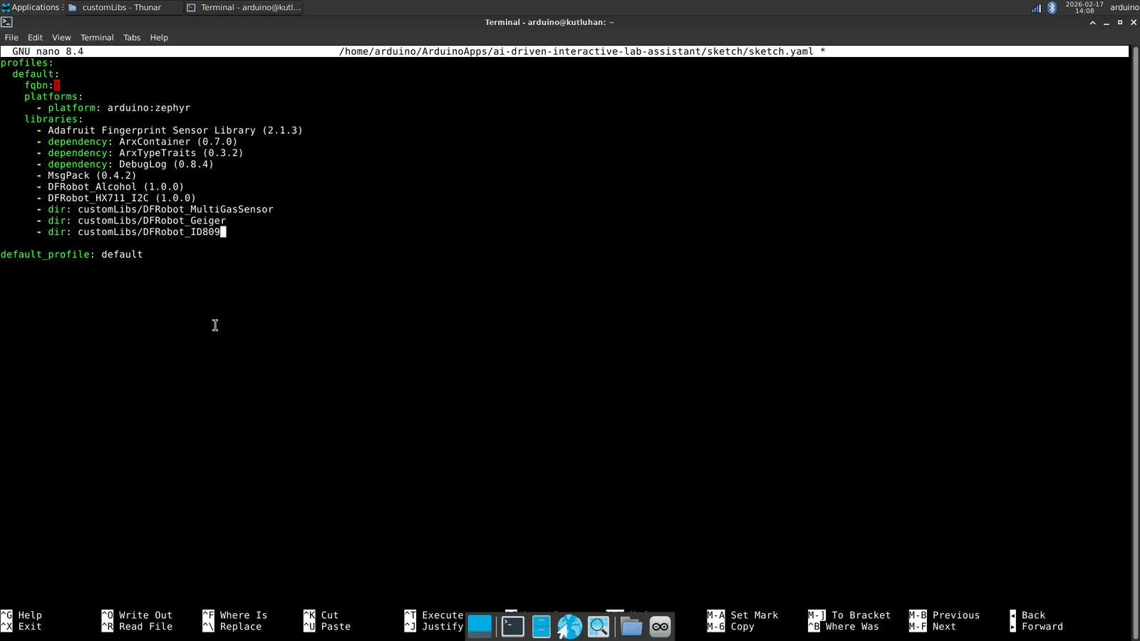

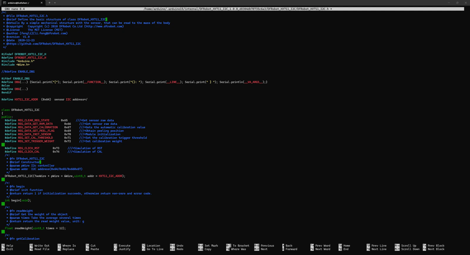
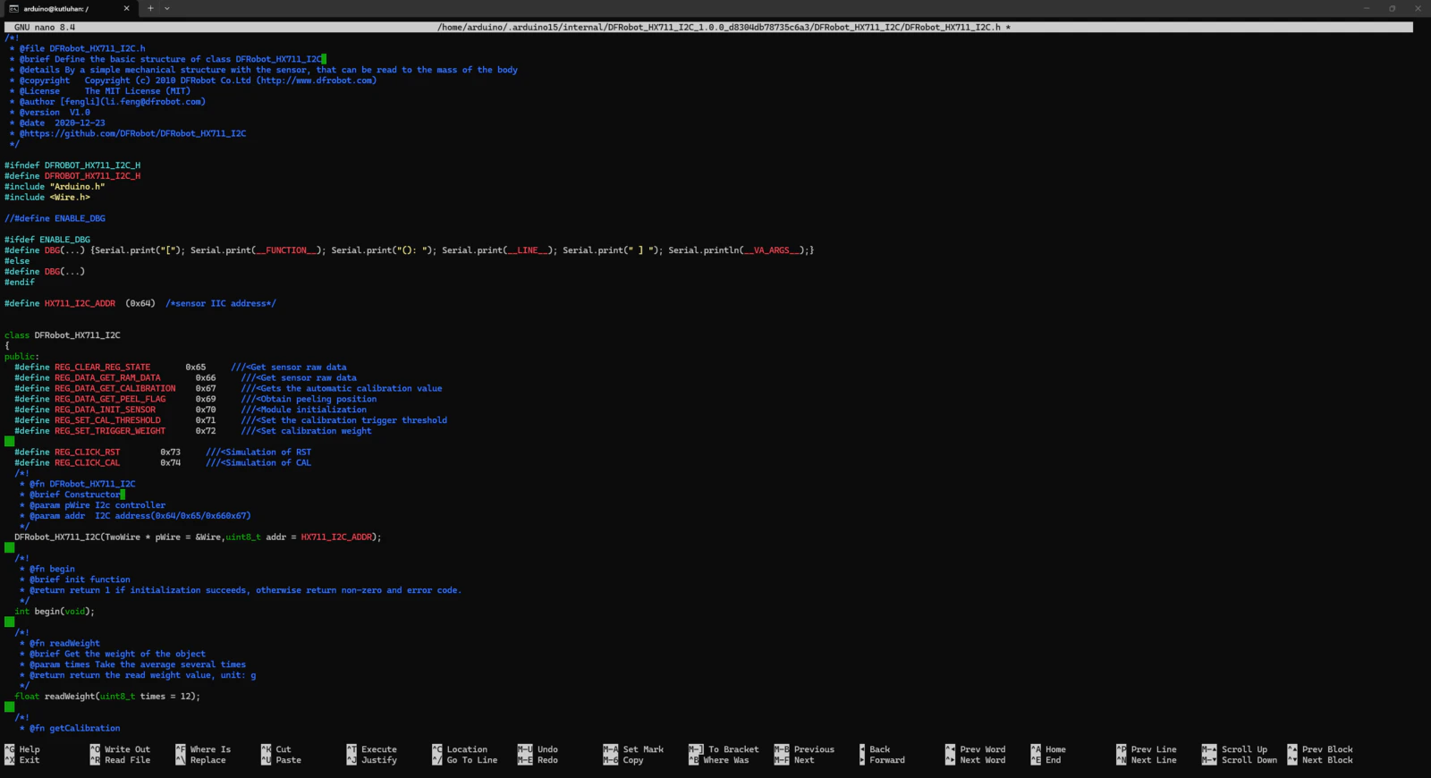
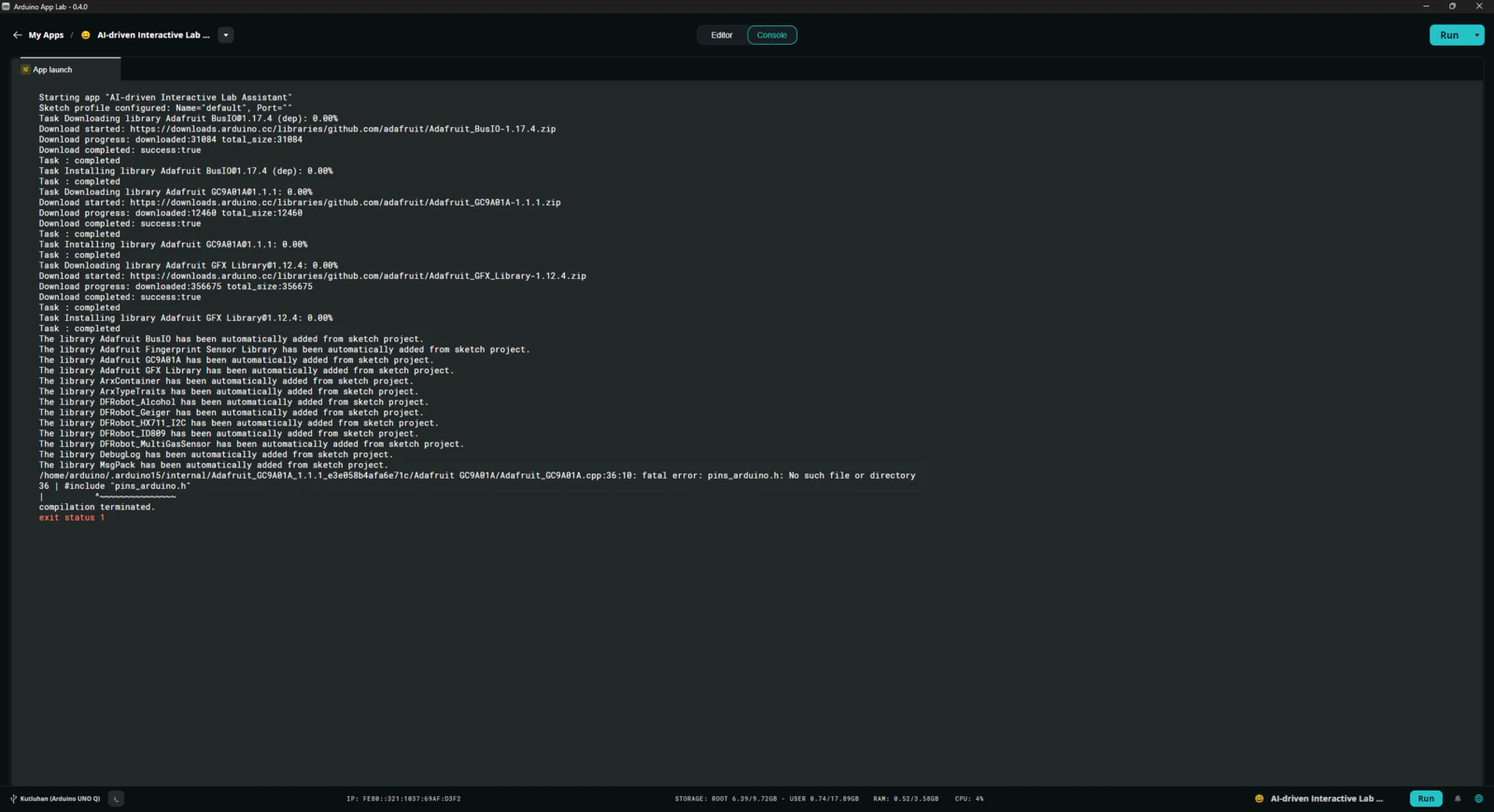
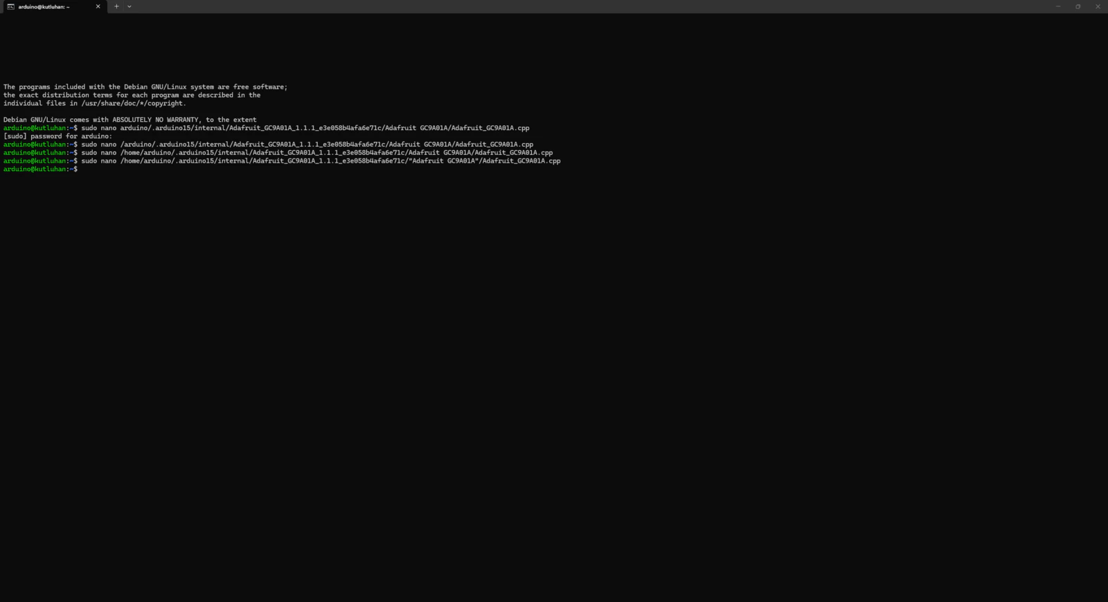
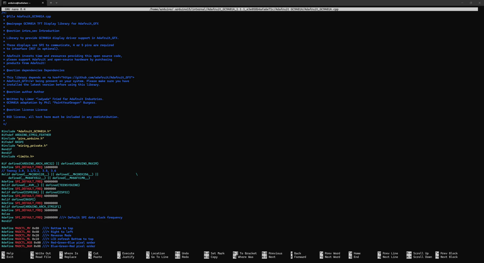
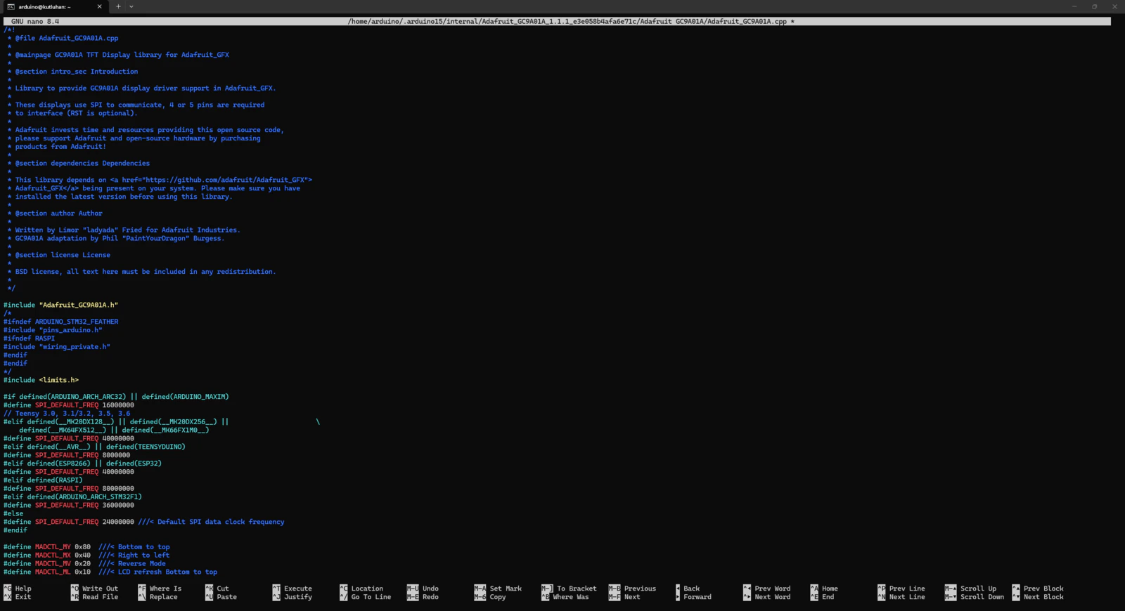
- dir: customLibs/modded_Adafruit_GC9A01A_1.1.1
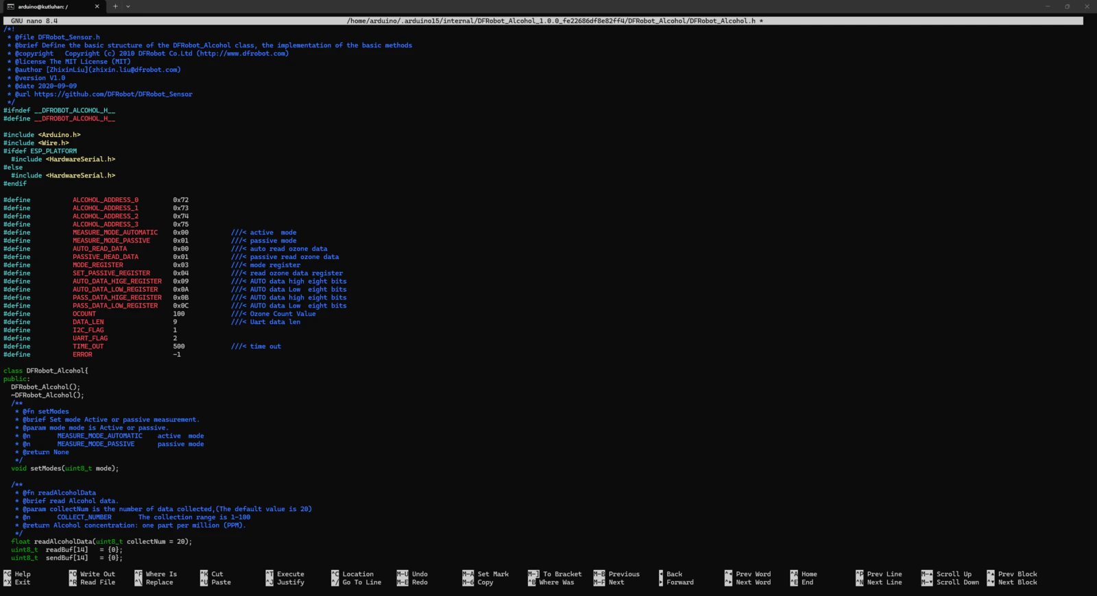
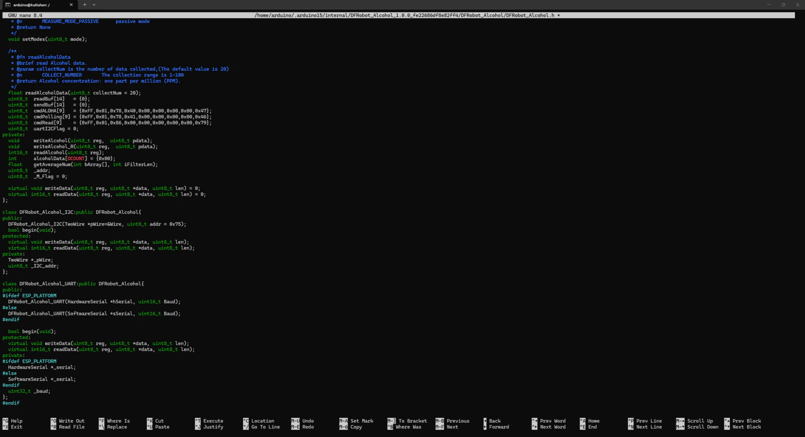
- dir: customLibs/modded_DFRobot_Alcohol_1.0.0
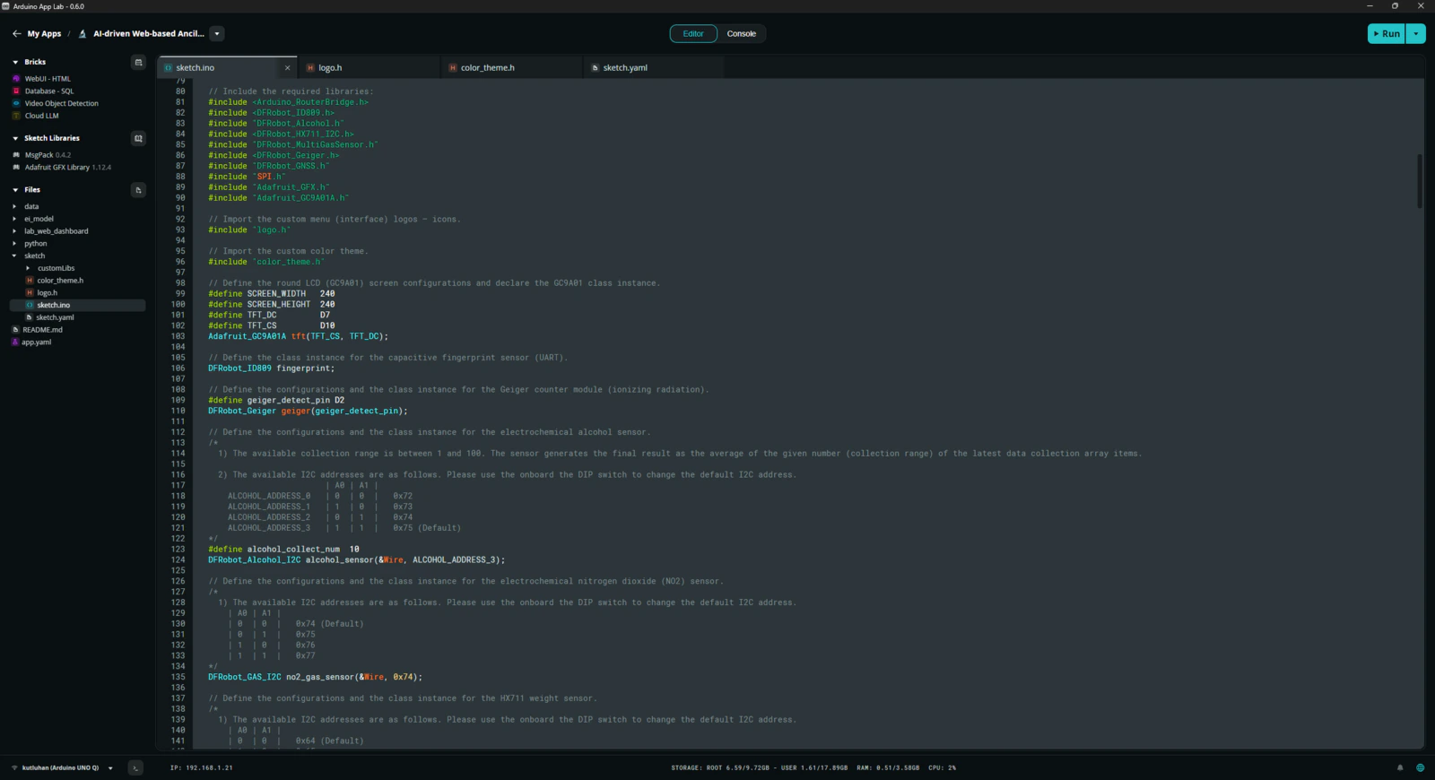
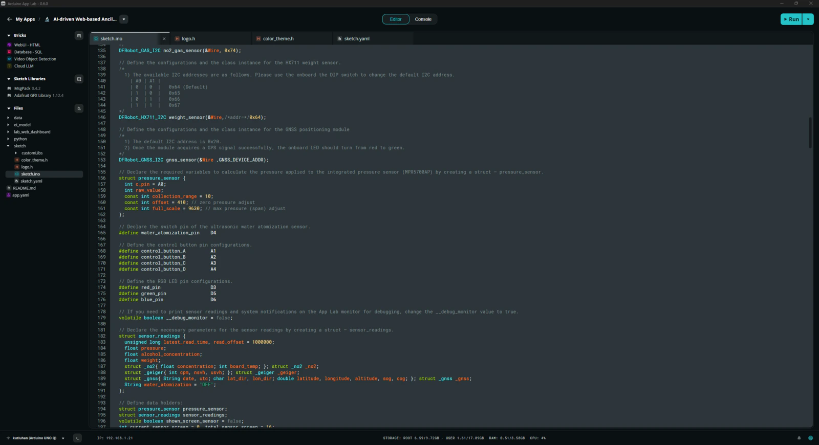
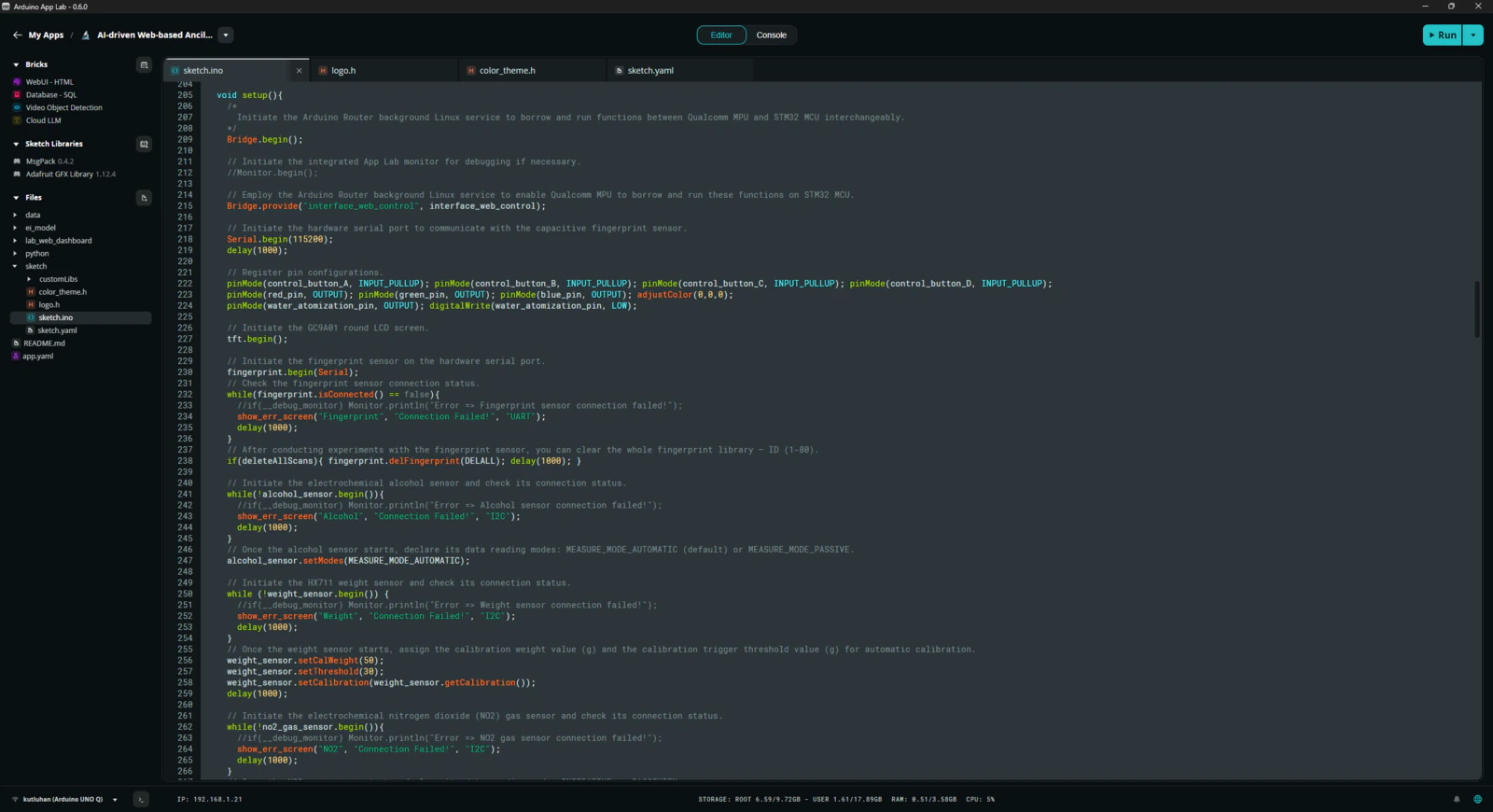
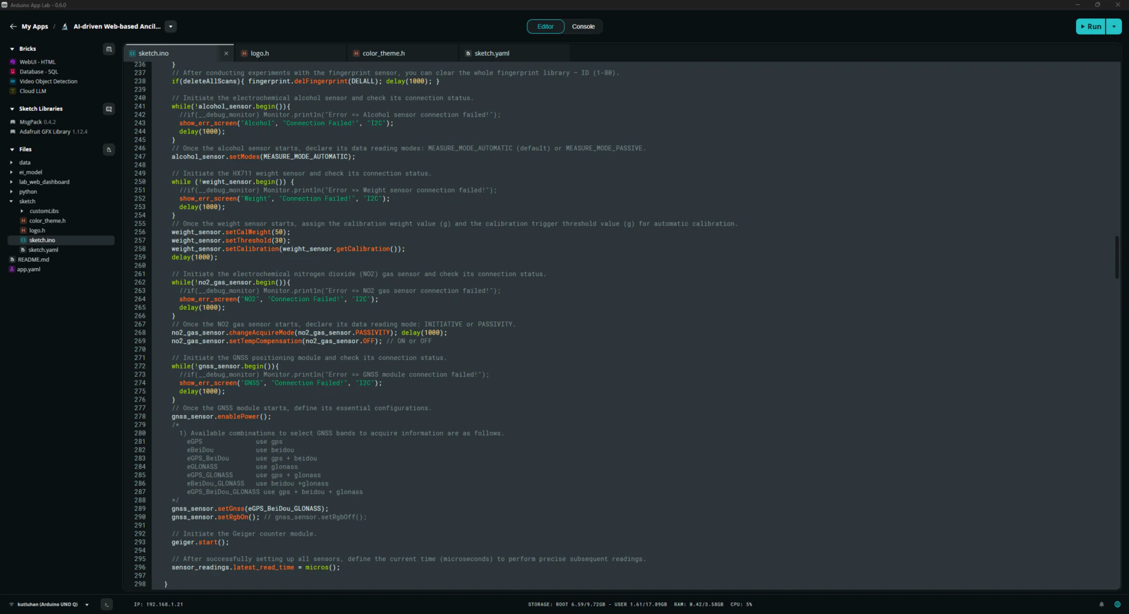
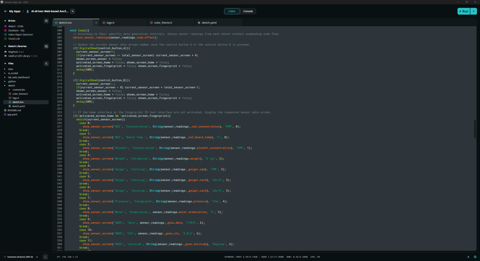
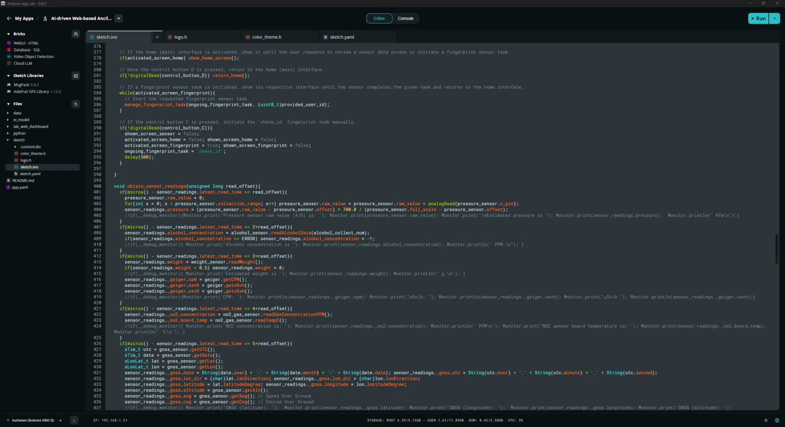
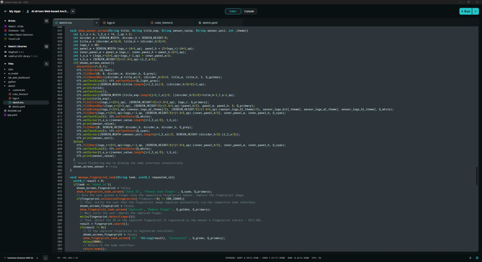
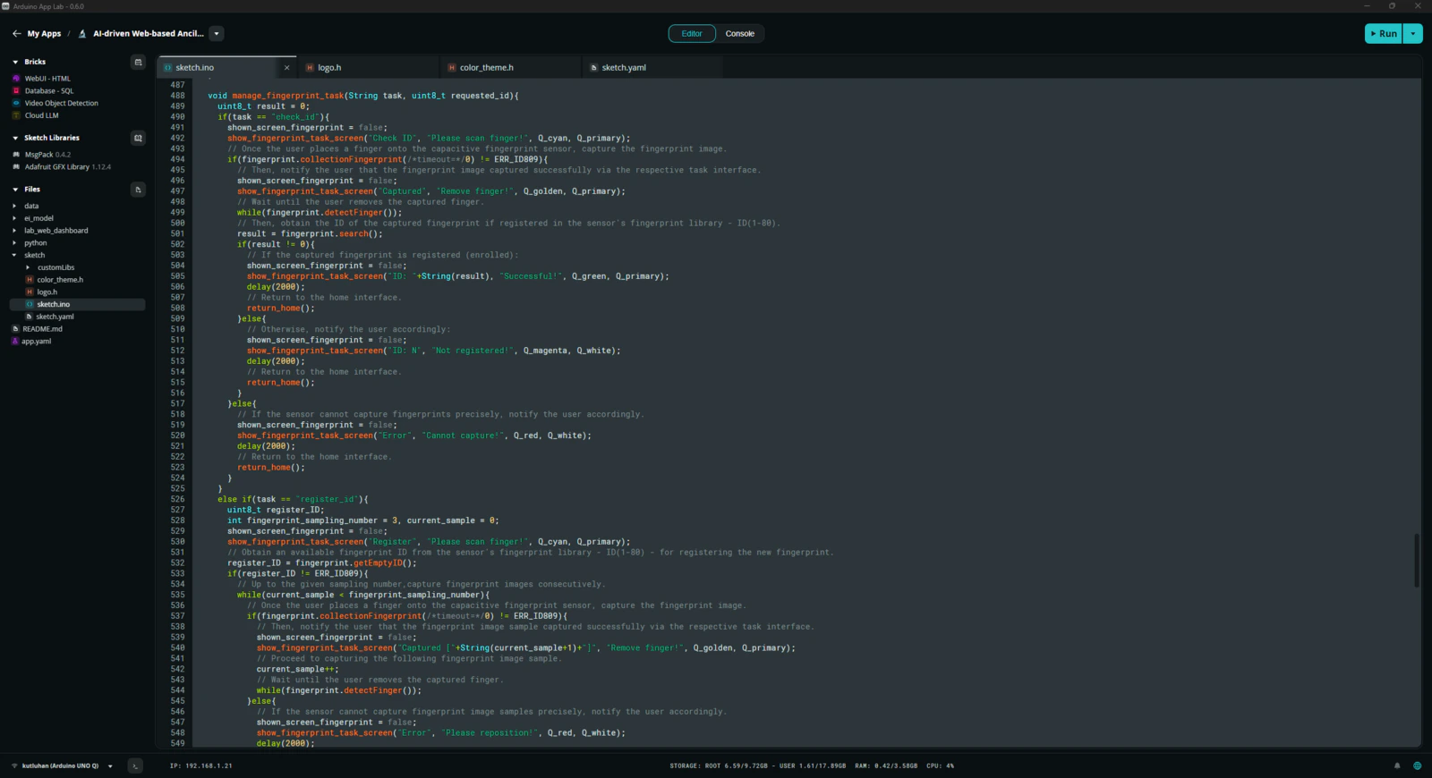
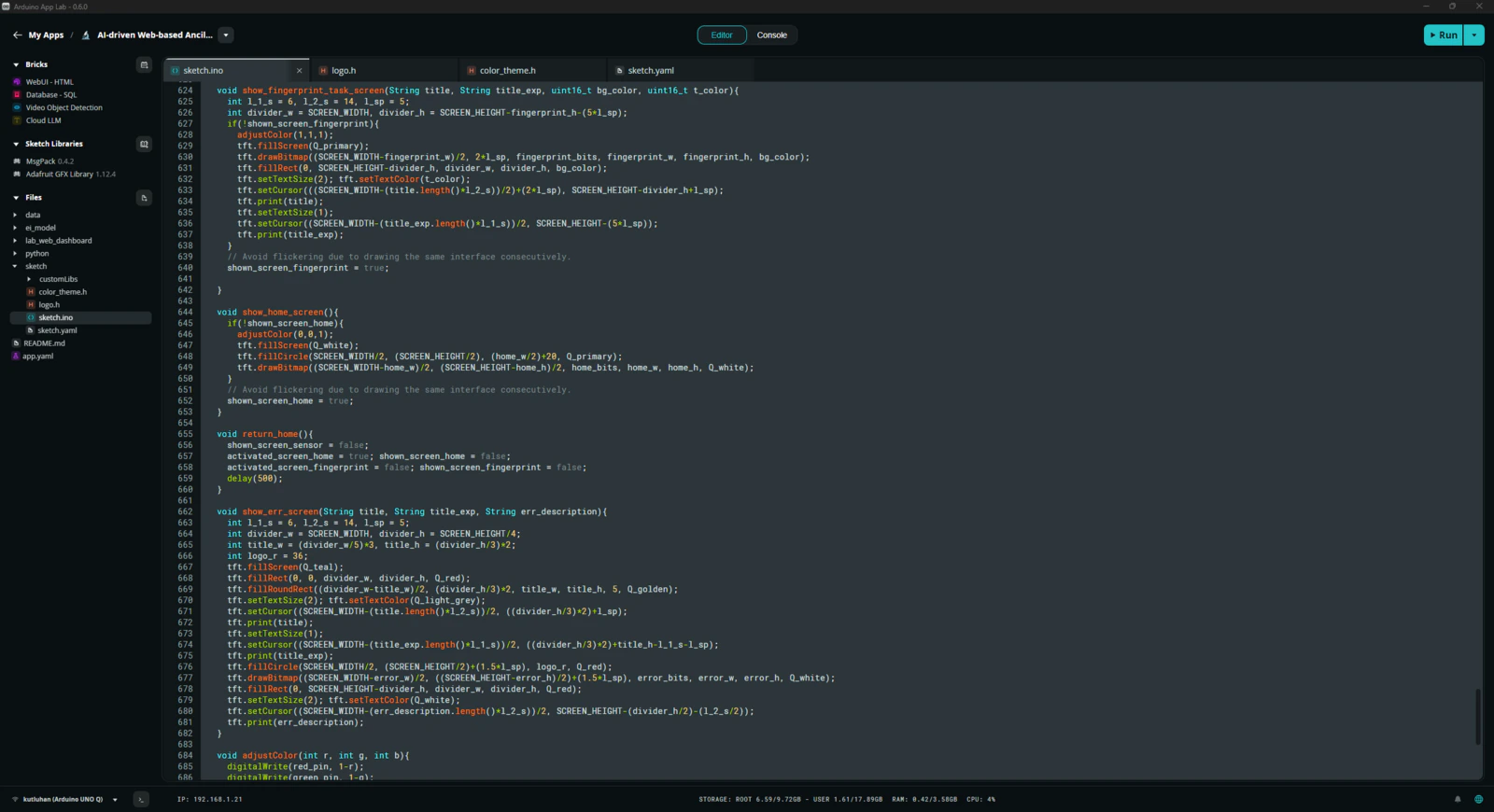
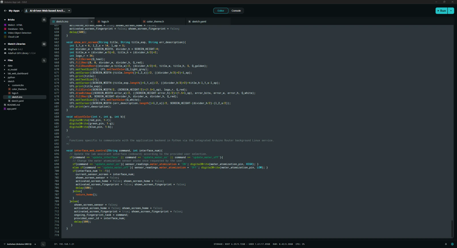
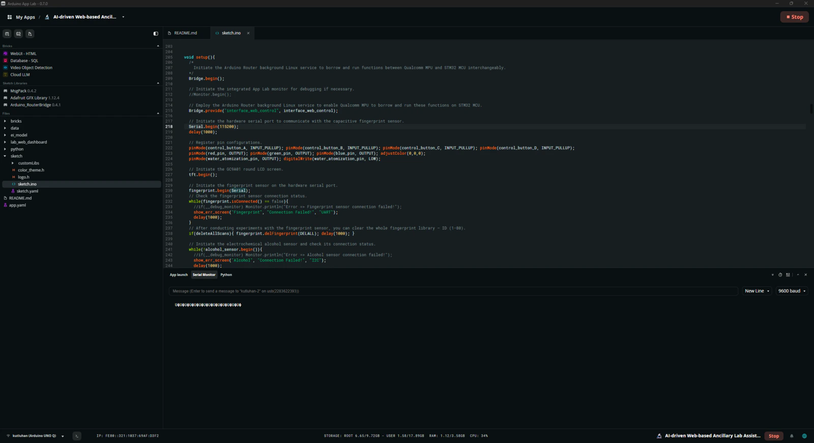
Step 2: Programming the Arduino sketch executed by the STM32U585 (MCU)
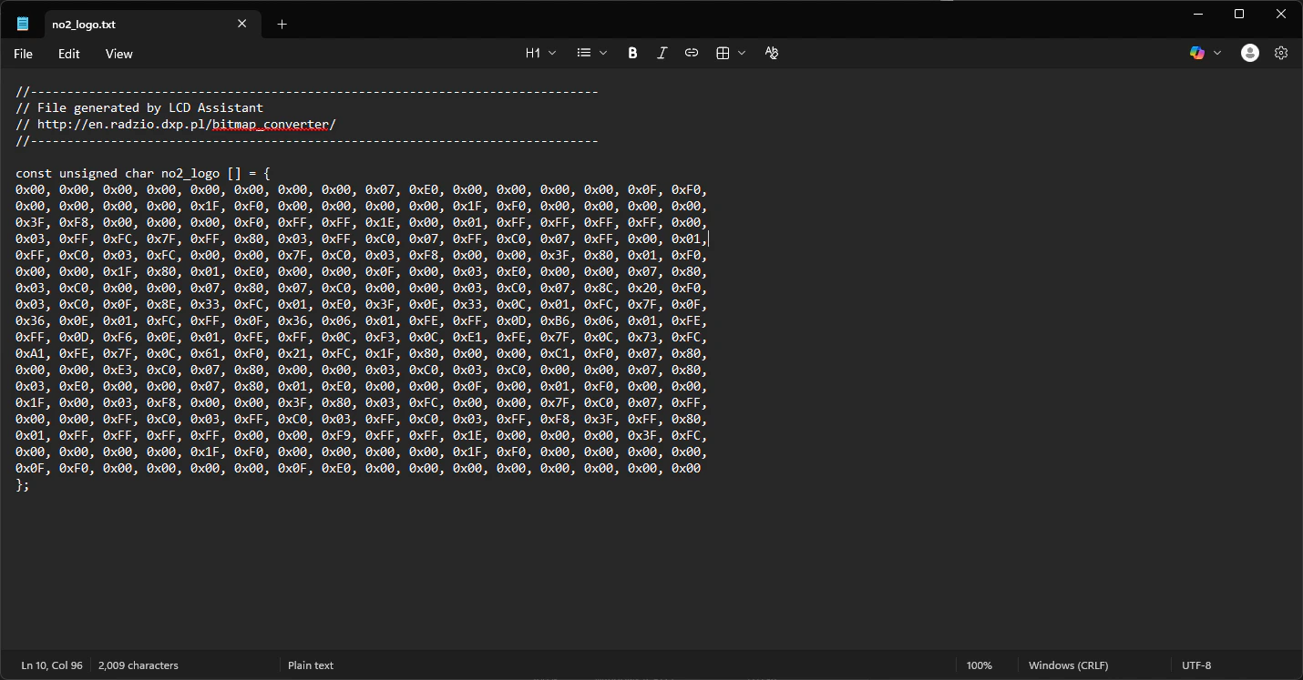
📁 logo.h To prepare monochromatic images in order to display custom logos on the round LCD module (GC9A01), I followed the process below. #️⃣ First, I converted monochromatic bitmaps to compatible C data arrays by utilizing LCD Assistant. #️⃣ Based on the round display type, I selected the Horizontal byte orientation. #️⃣ After converting all logos successfully, I created this header file — logo.h — to store them.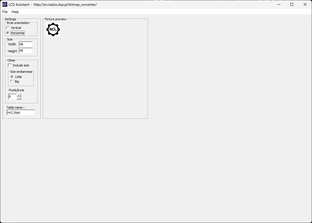
Step 3: Collecting images of different lab equipment to construct a valid data set
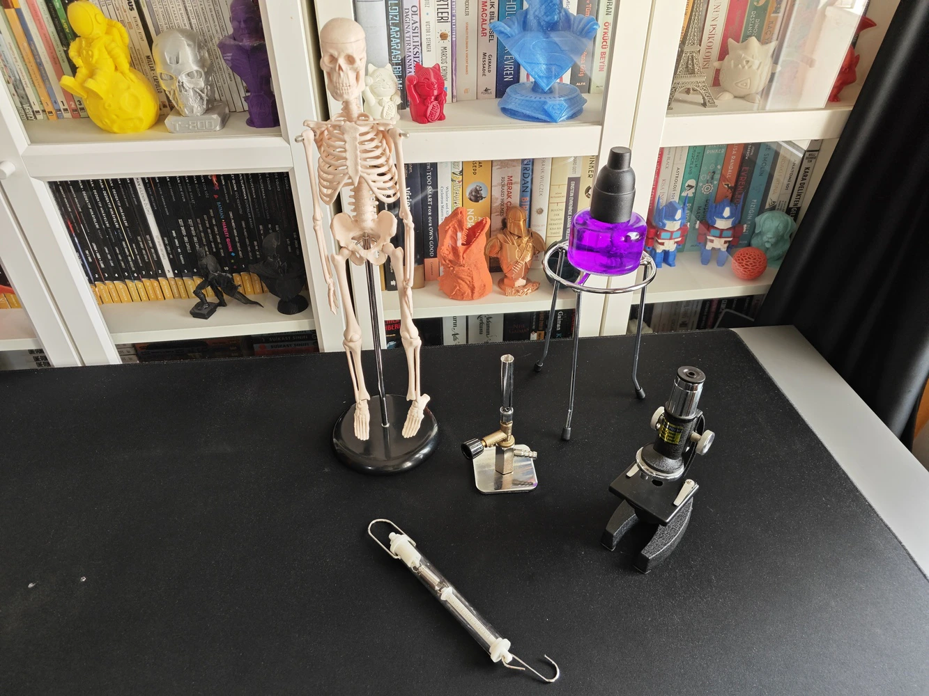
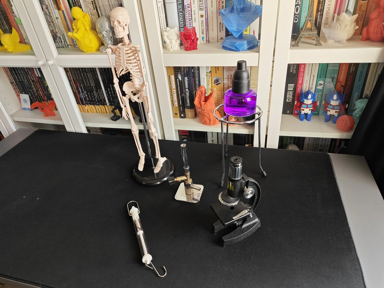
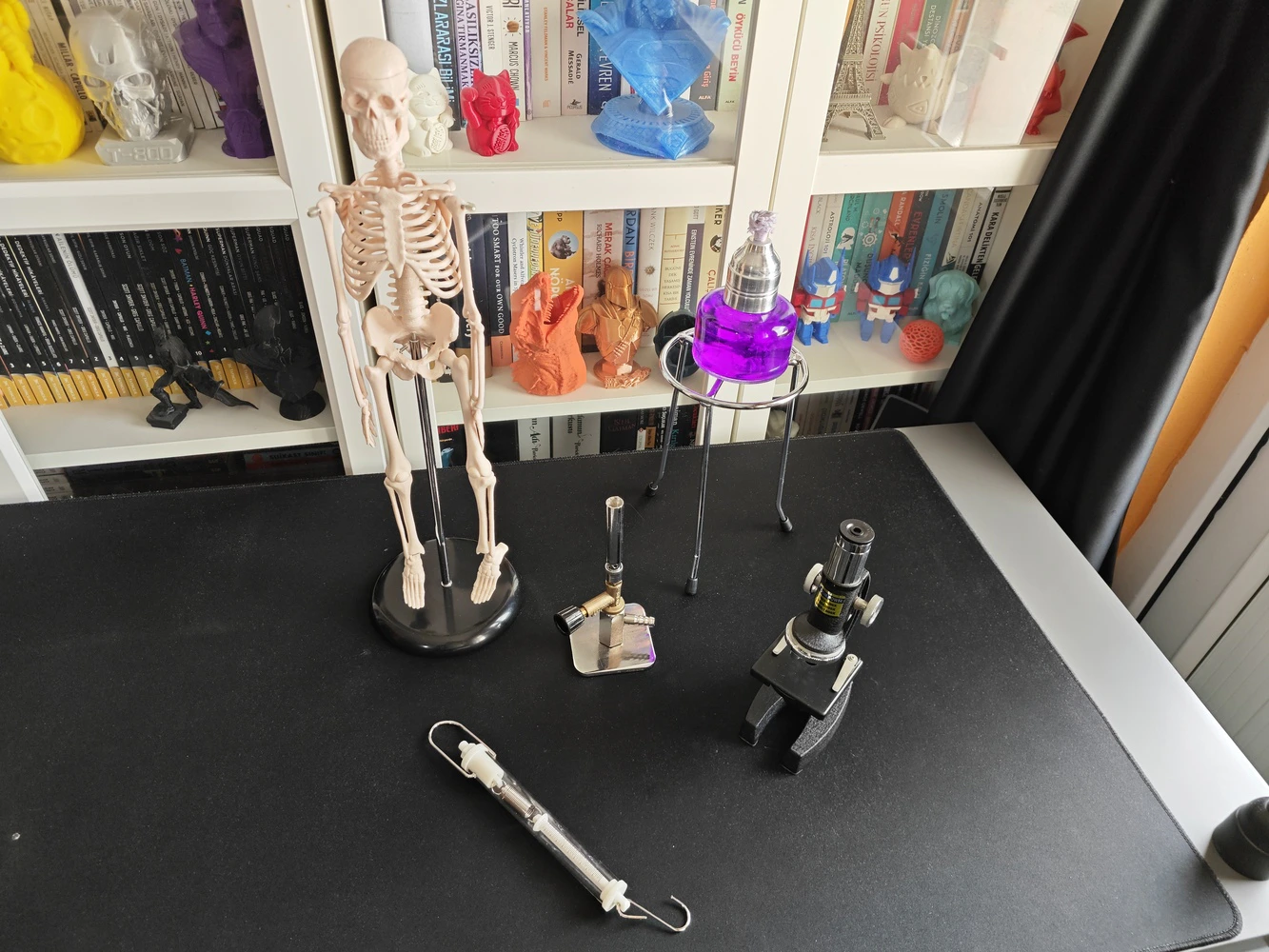
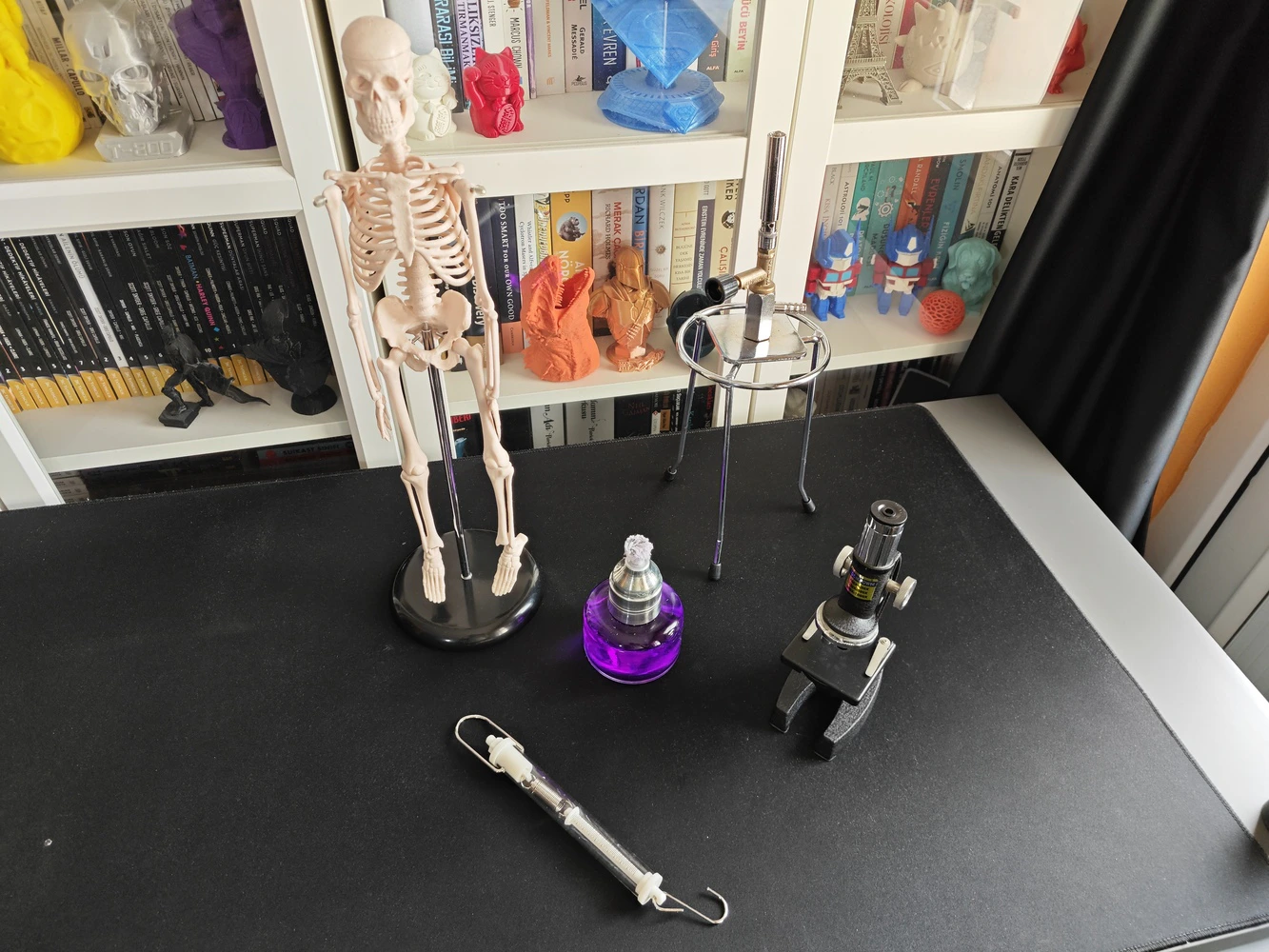
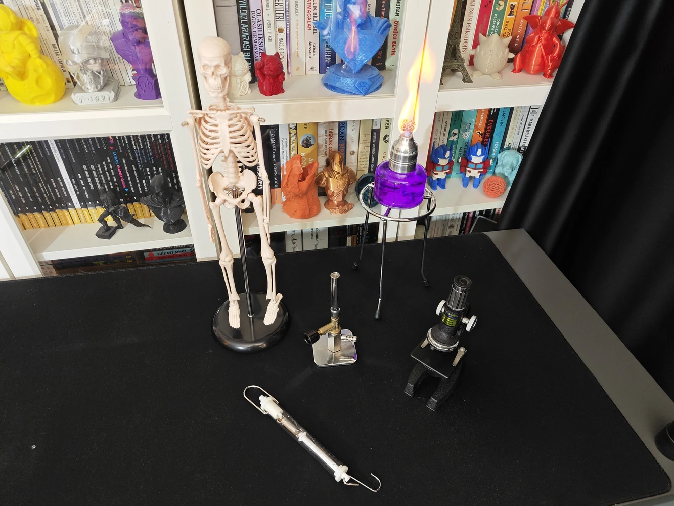
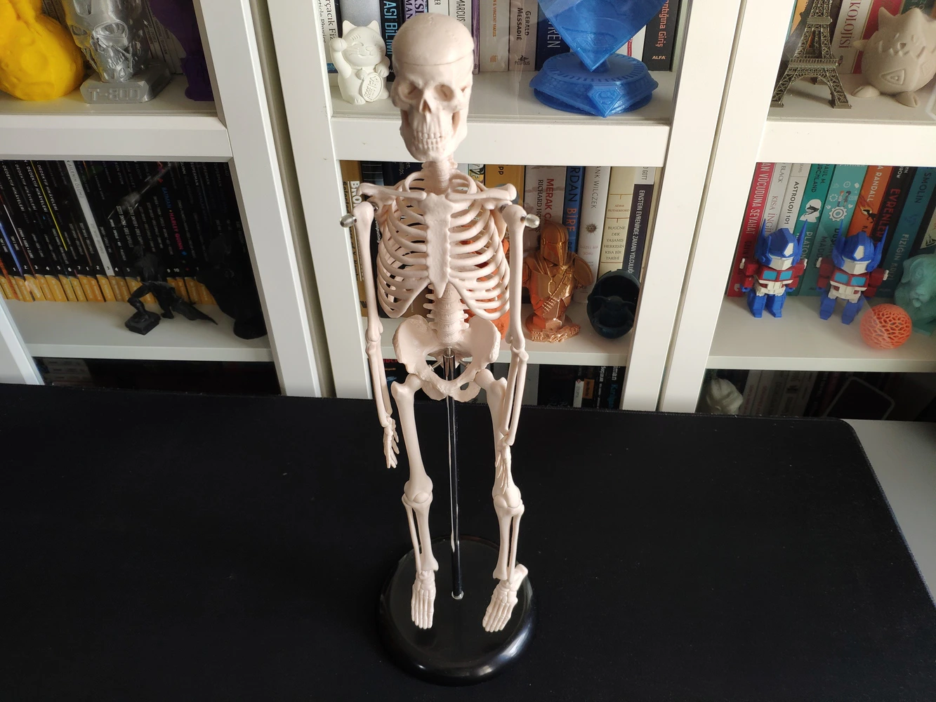
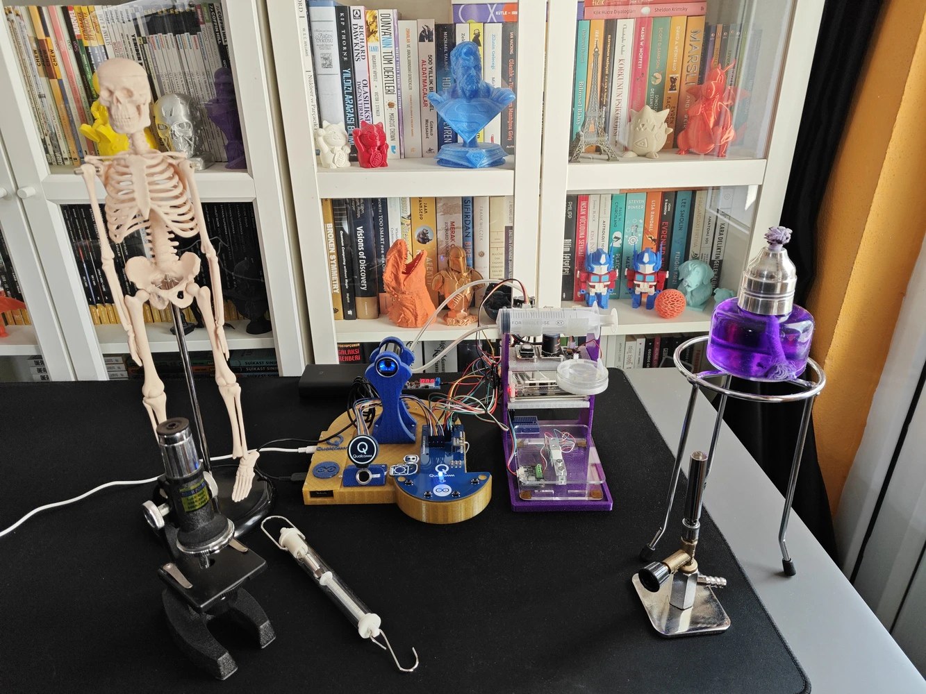
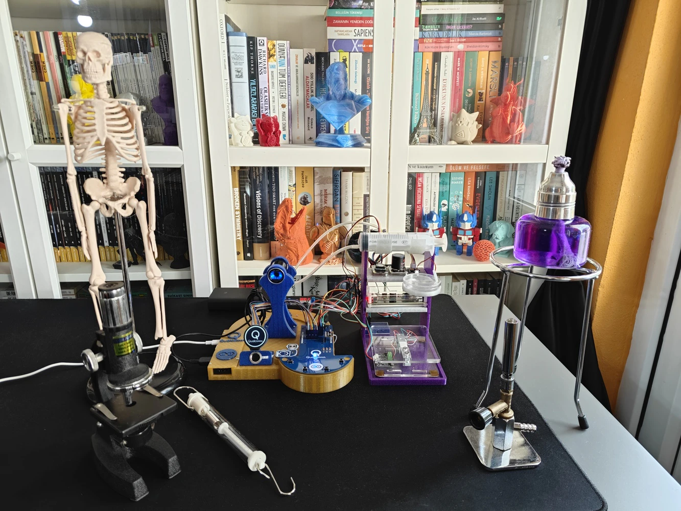
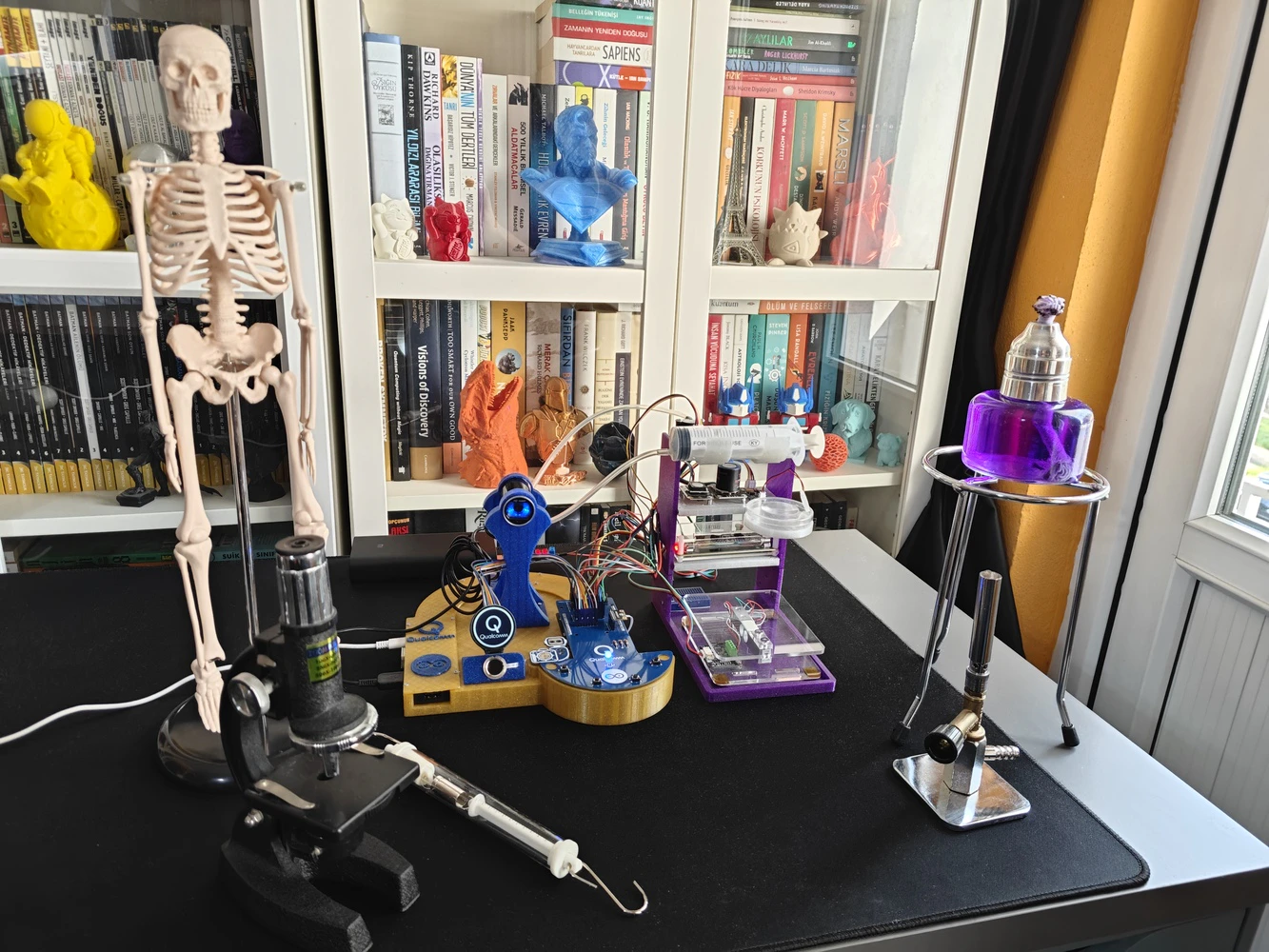
As mentioned earlier, this AI-driven ancillary lab assistant is the second iteration of my previous lab assistant project. Therefore, I already had a diverse set of lab equipment to construct my data set. Since I took a different approach and modified equipment image samples by applying specific built-in OpenCV filters in my previous project, I decided to collect fresh image samples and reduce the number of equipment types. After mulling over different lab equipment options, I decided to construct my data set based on these items:- Human skeleton model
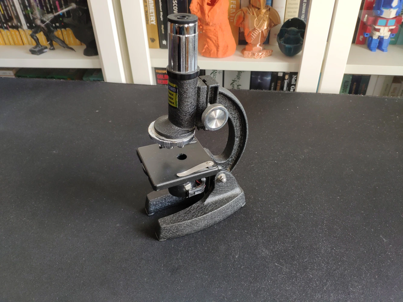
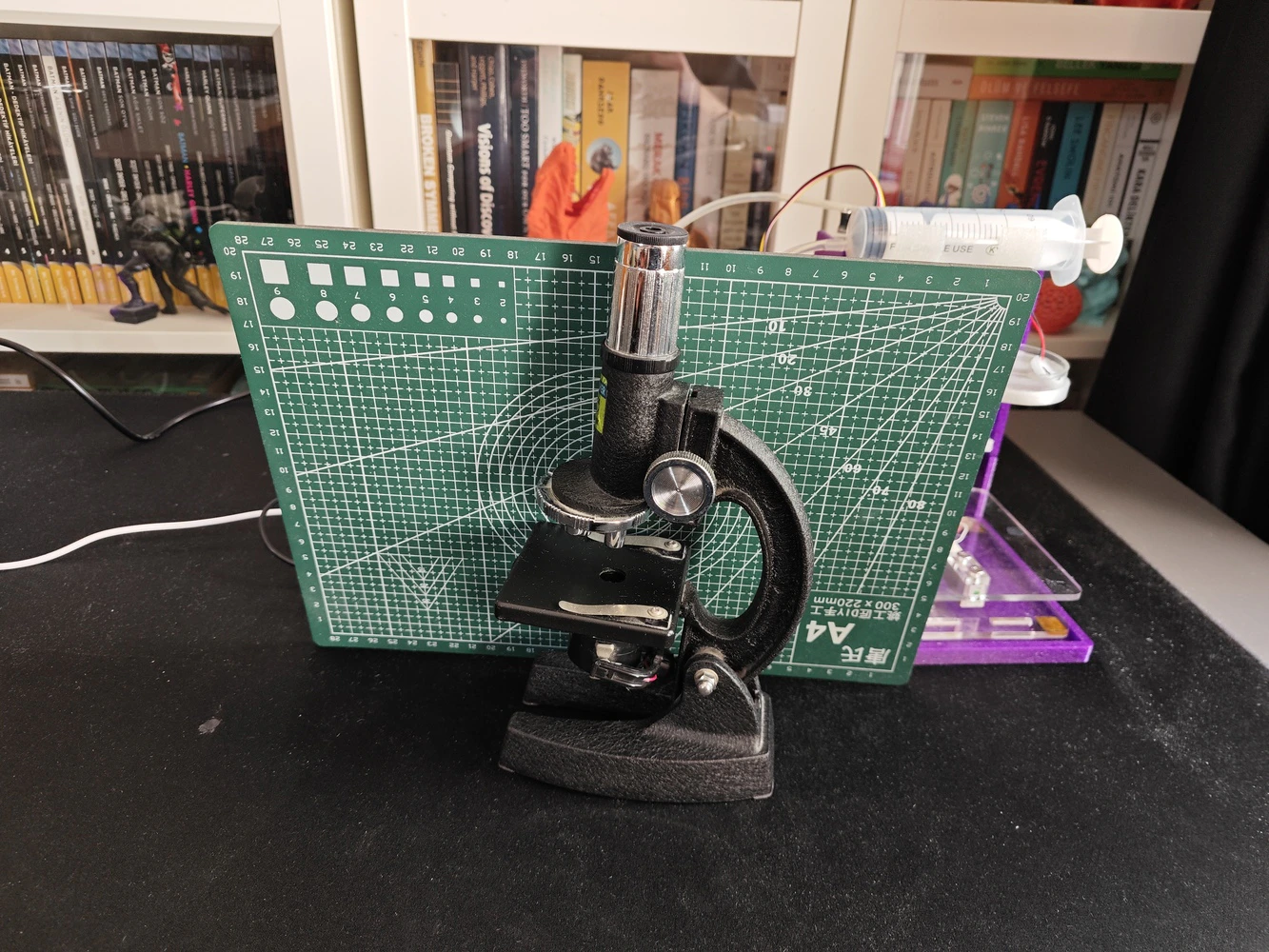
- Microscope
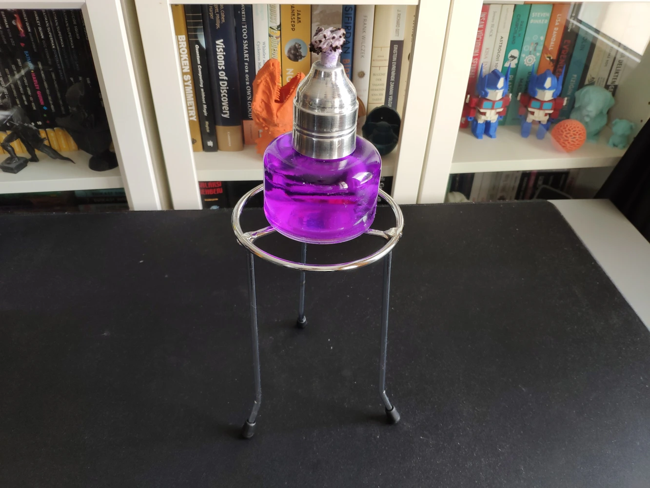
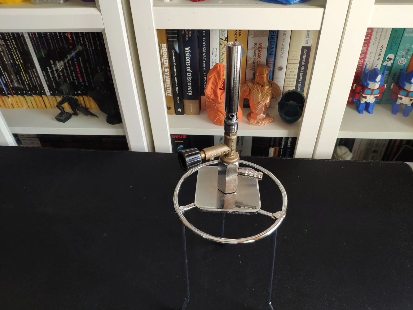
- Alcohol burner
- Bunsen burner
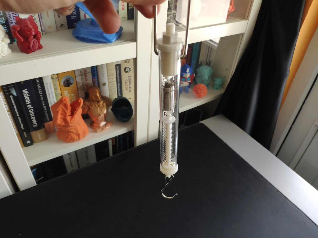
- Dynamometer
Step 4: Building an object detection model (FOMO) w/ Edge Impulse Enterprise
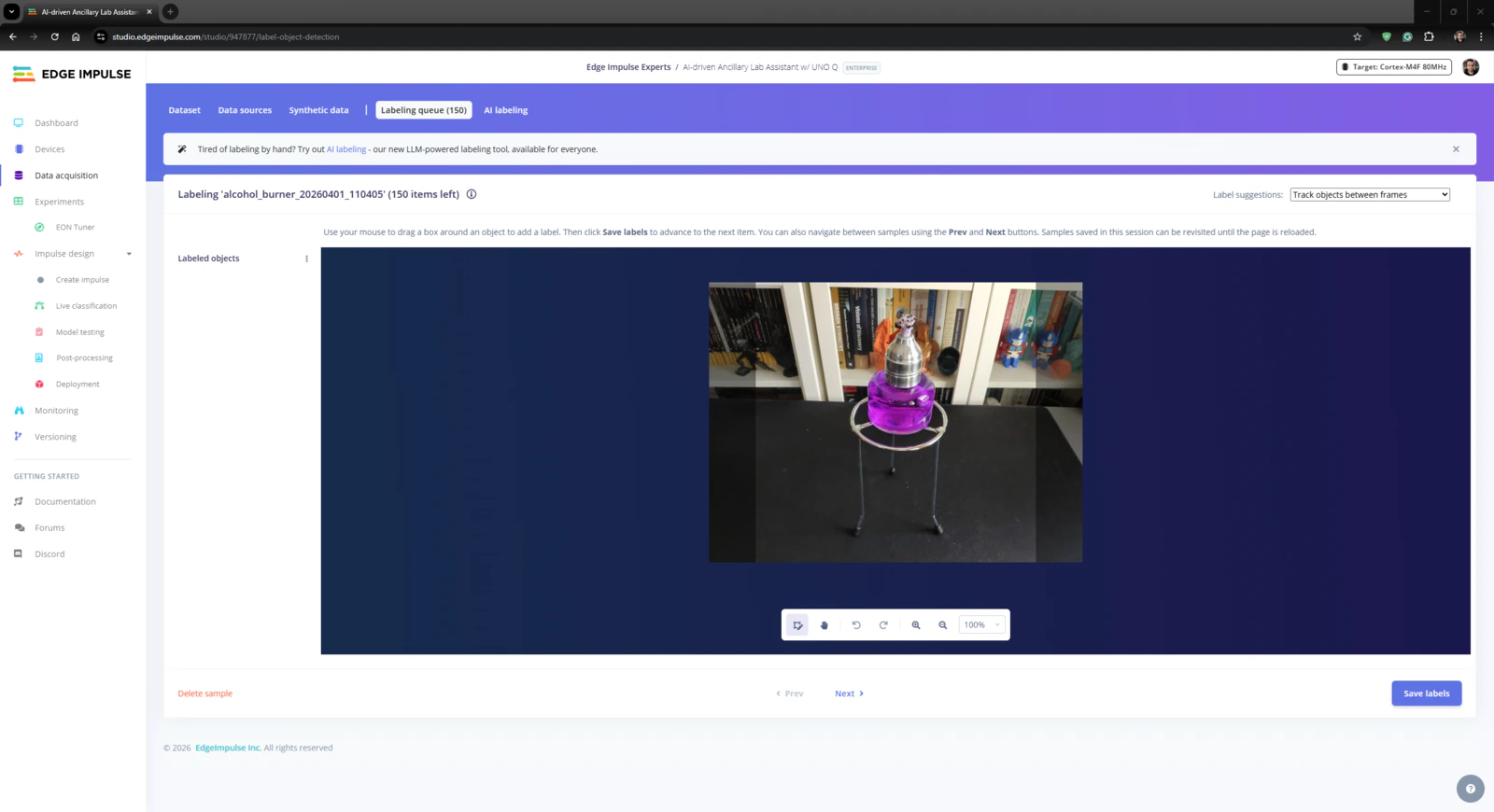
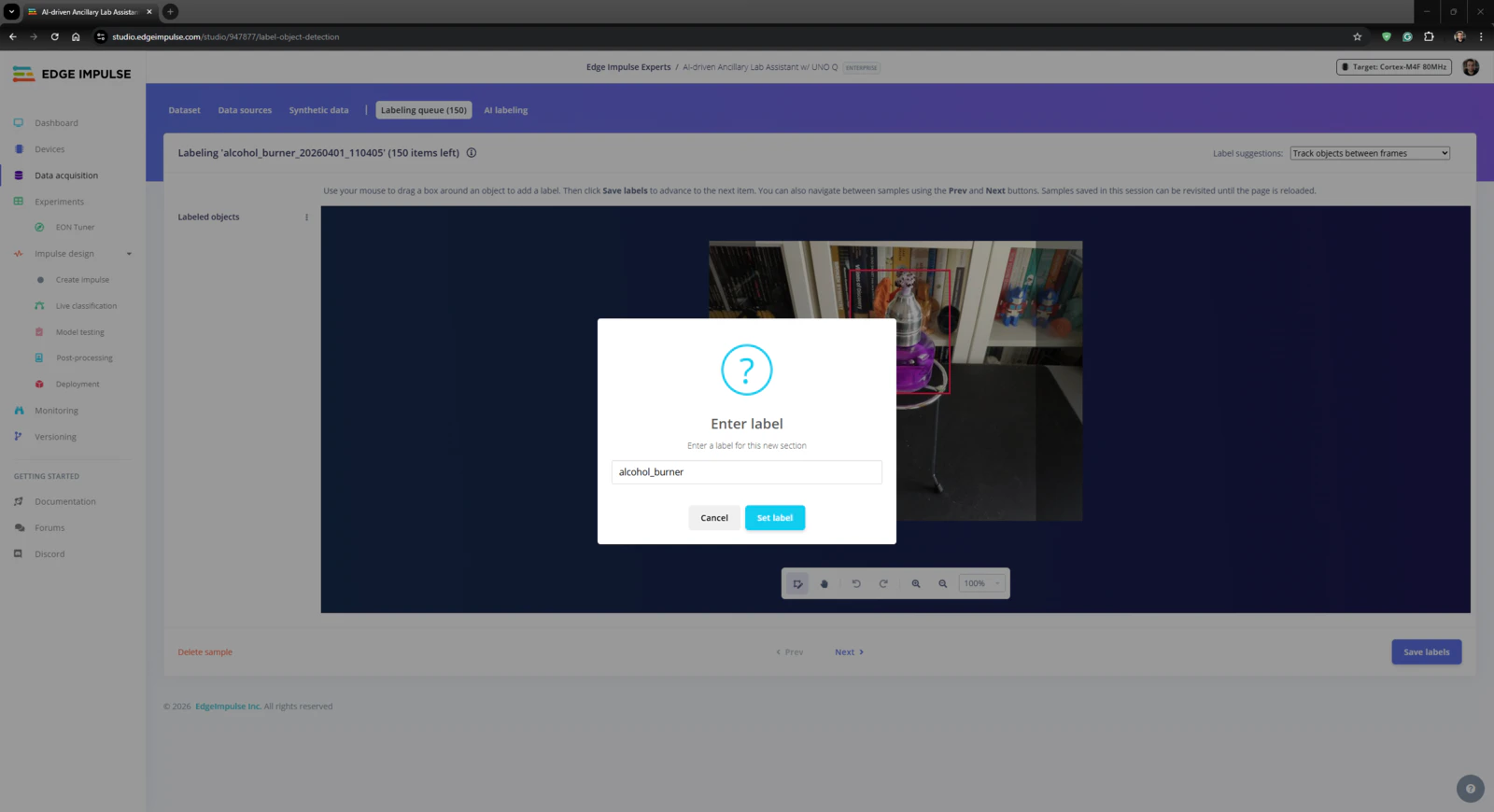
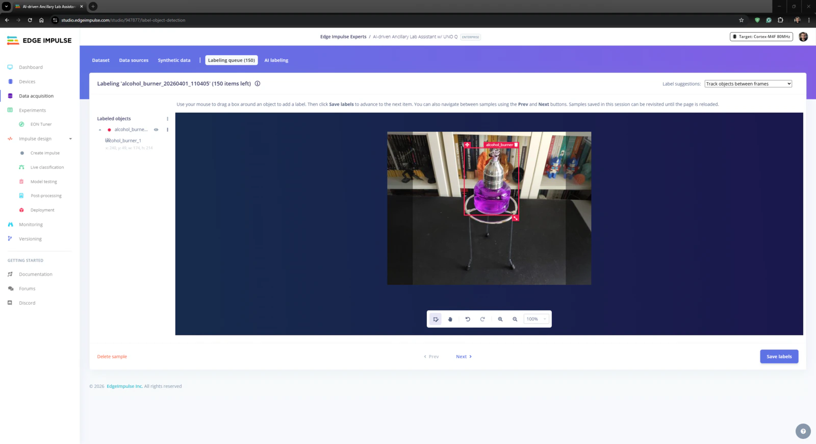
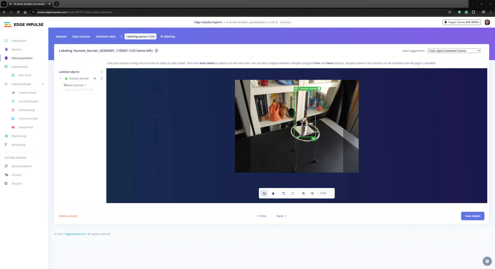
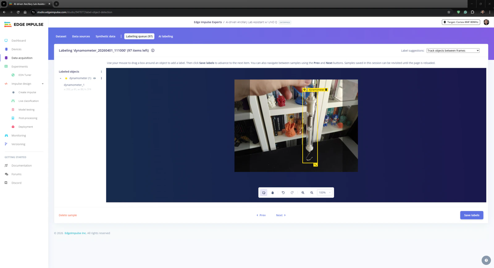
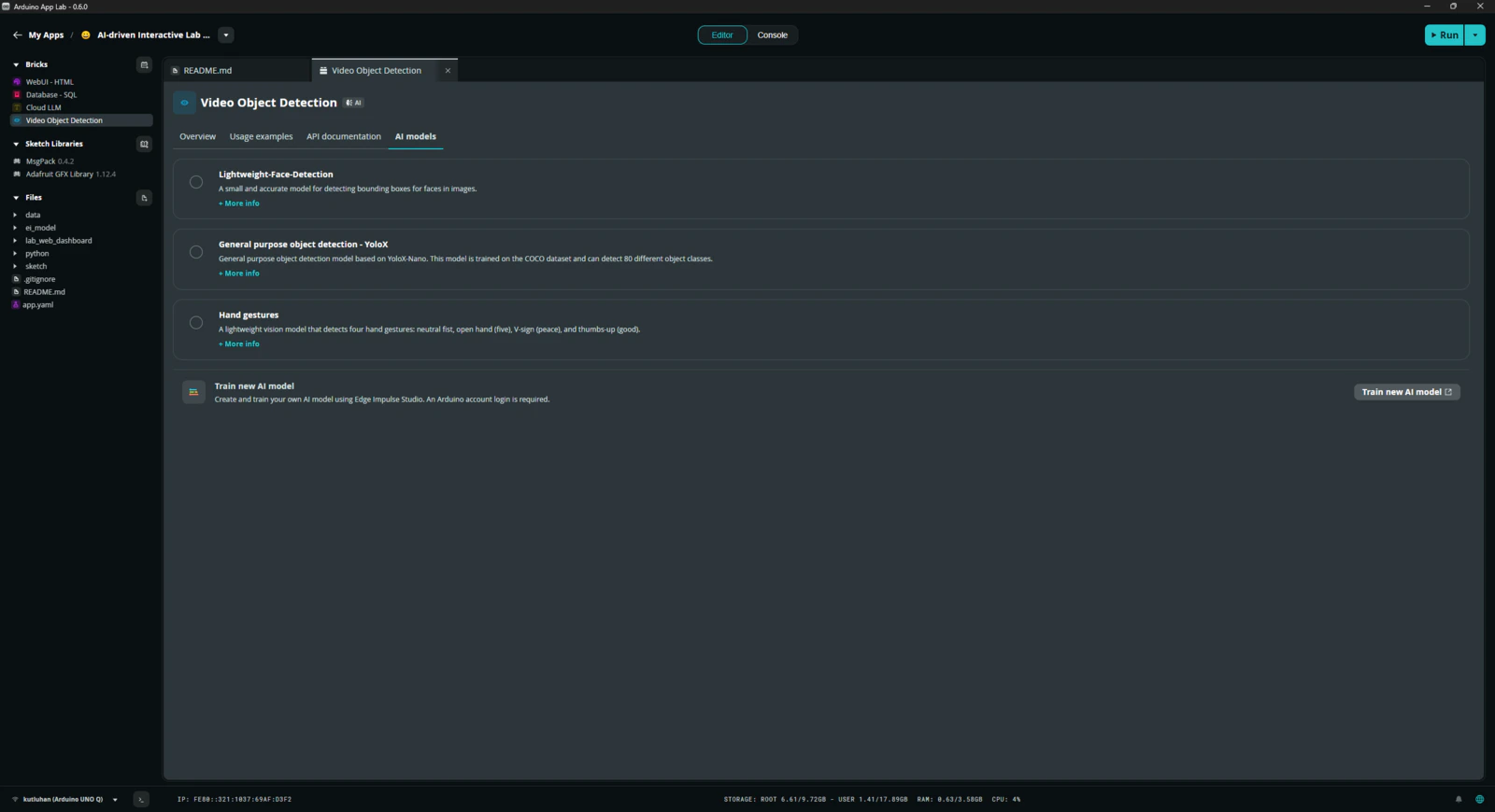
Since Edge Impulse provides developer-friendly tools for advanced AI applications and supports almost every development board through its vast model deployment options, I decided to utilize Edge Impulse Enterprise to build my object detection model. Also, Edge Impulse Enterprise incorporates elaborate model architectures for advanced computer vision applications and optimizes the state-of-the-art vision models for edge devices and single-board computers such as Arduino UNO Q. Among the diverse machine learning algorithms provided by Edge Impulse, I decided to employ FOMO (Faster Objects, More Objects) since it is a groundbreaking algorithm optimized for both highly constrained edge devices and powerful single-board computers. While labeling the lab equipment image samples, I simply applied the name of the target lab equipment:- skeleton_model
- microscope
- alcohol_burner
- bunsen_burner
- dynamometer
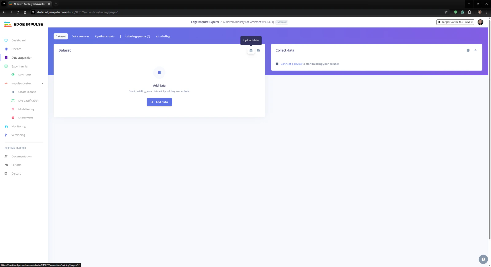
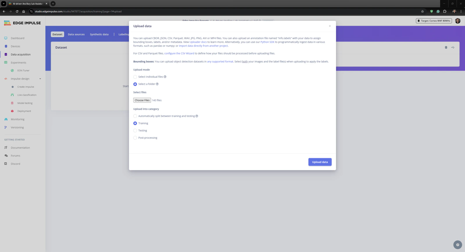
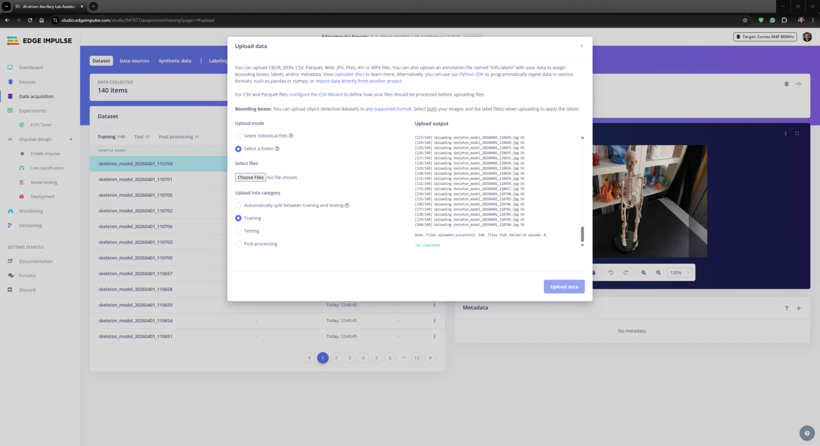
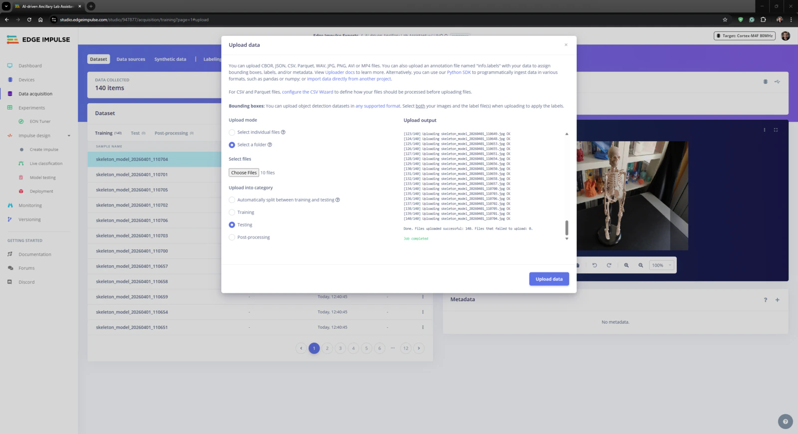
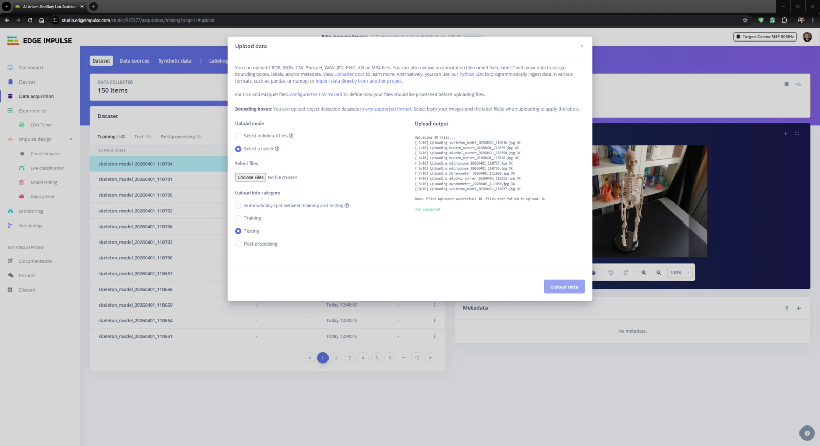
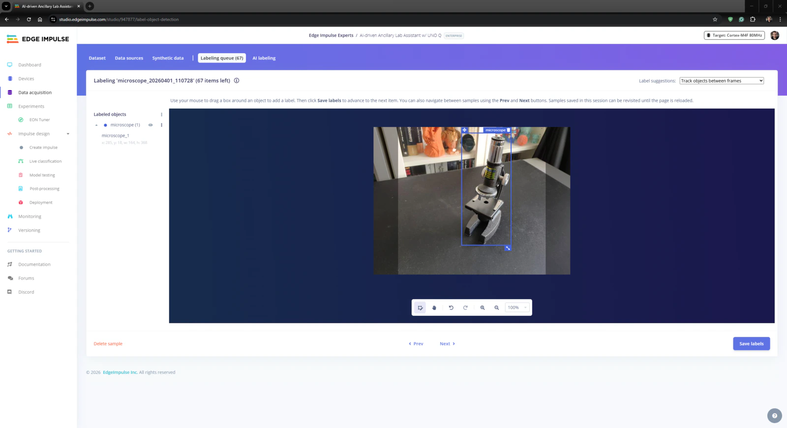
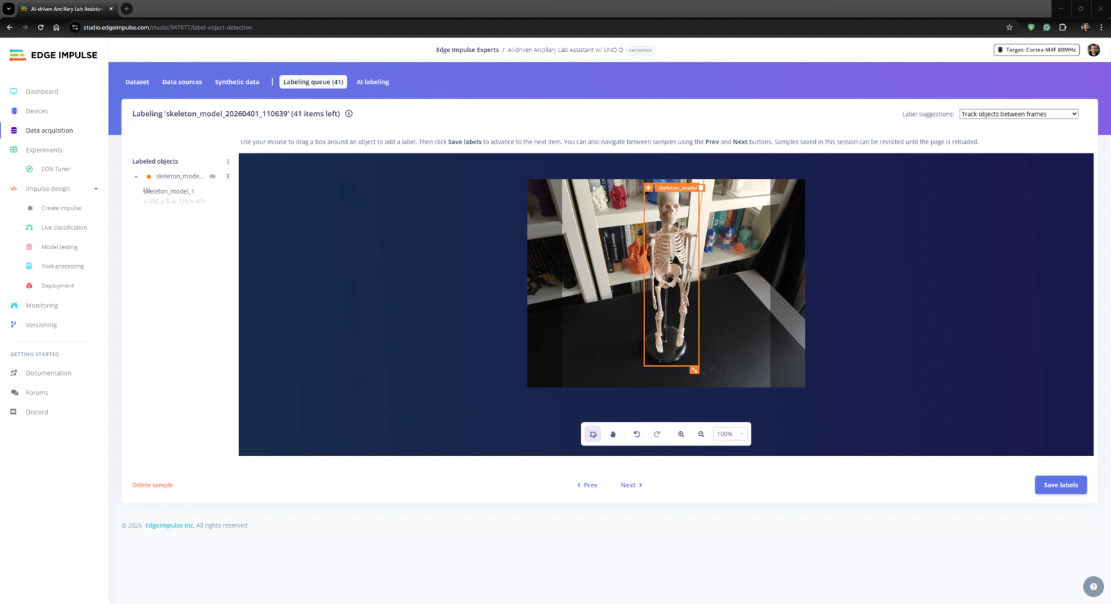
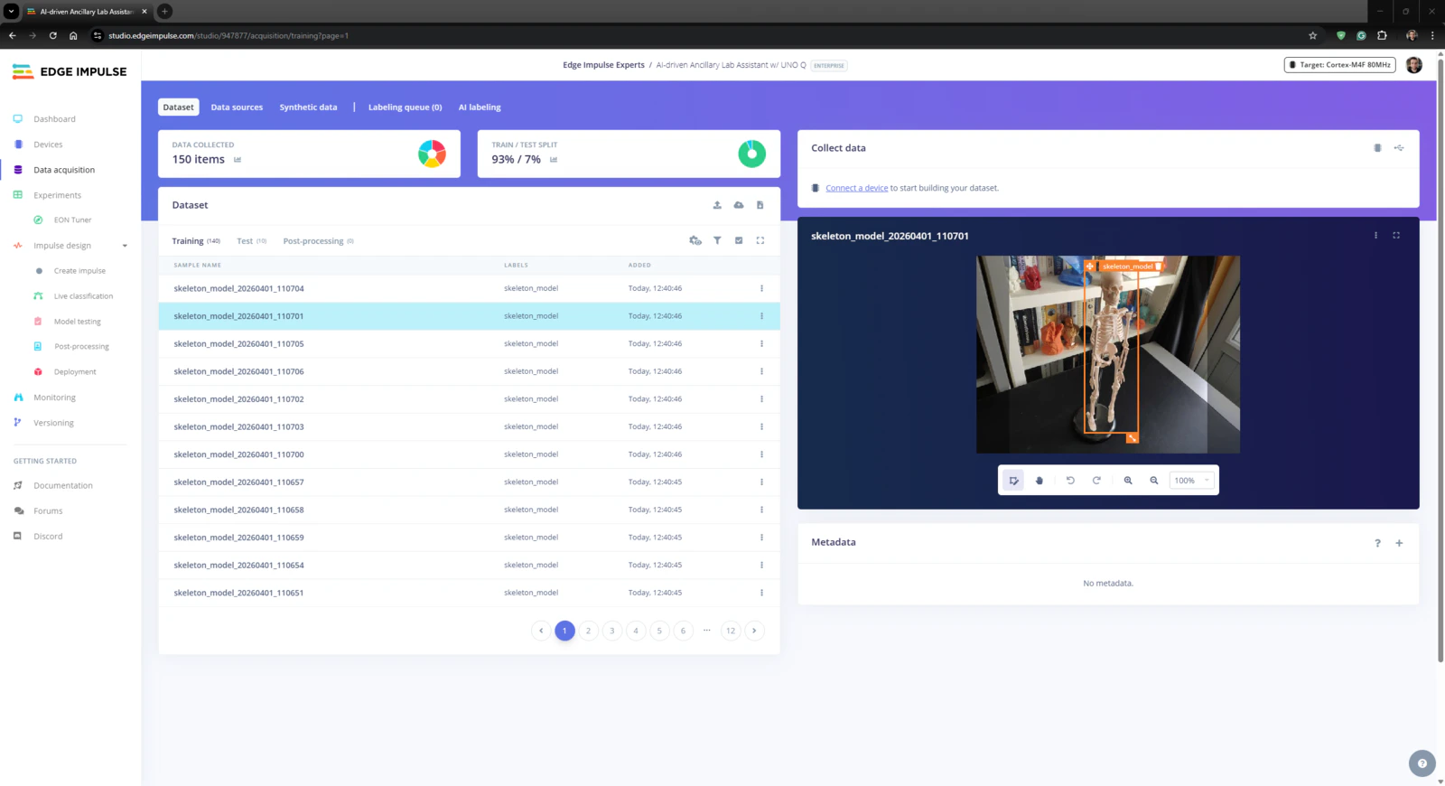
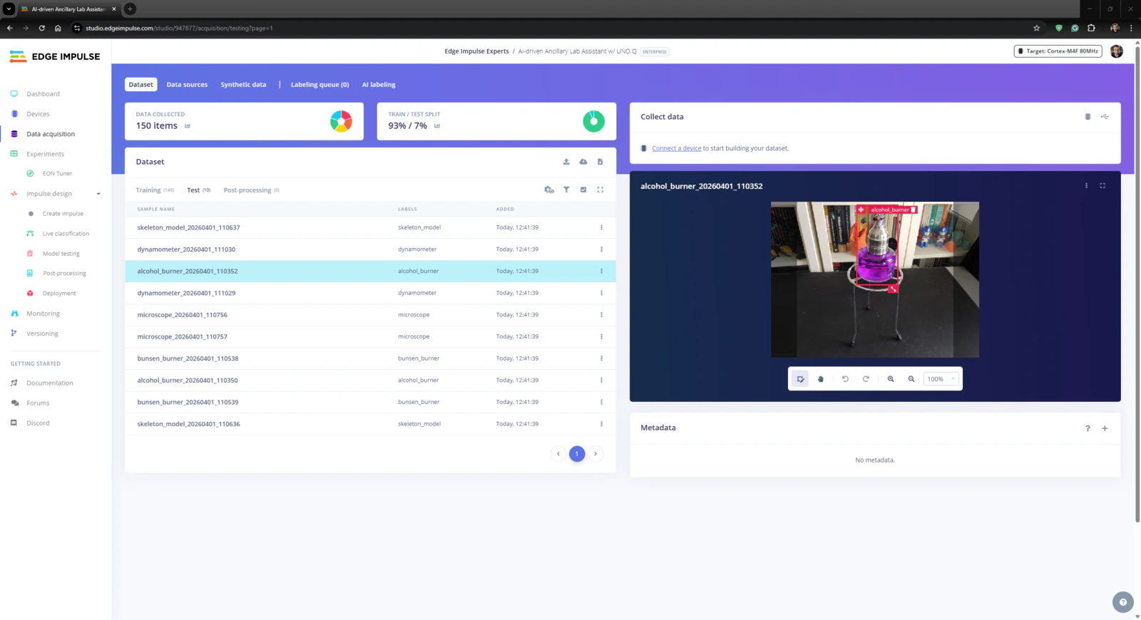
Step 4.1: Uploading and labeling the lab equipment image samples
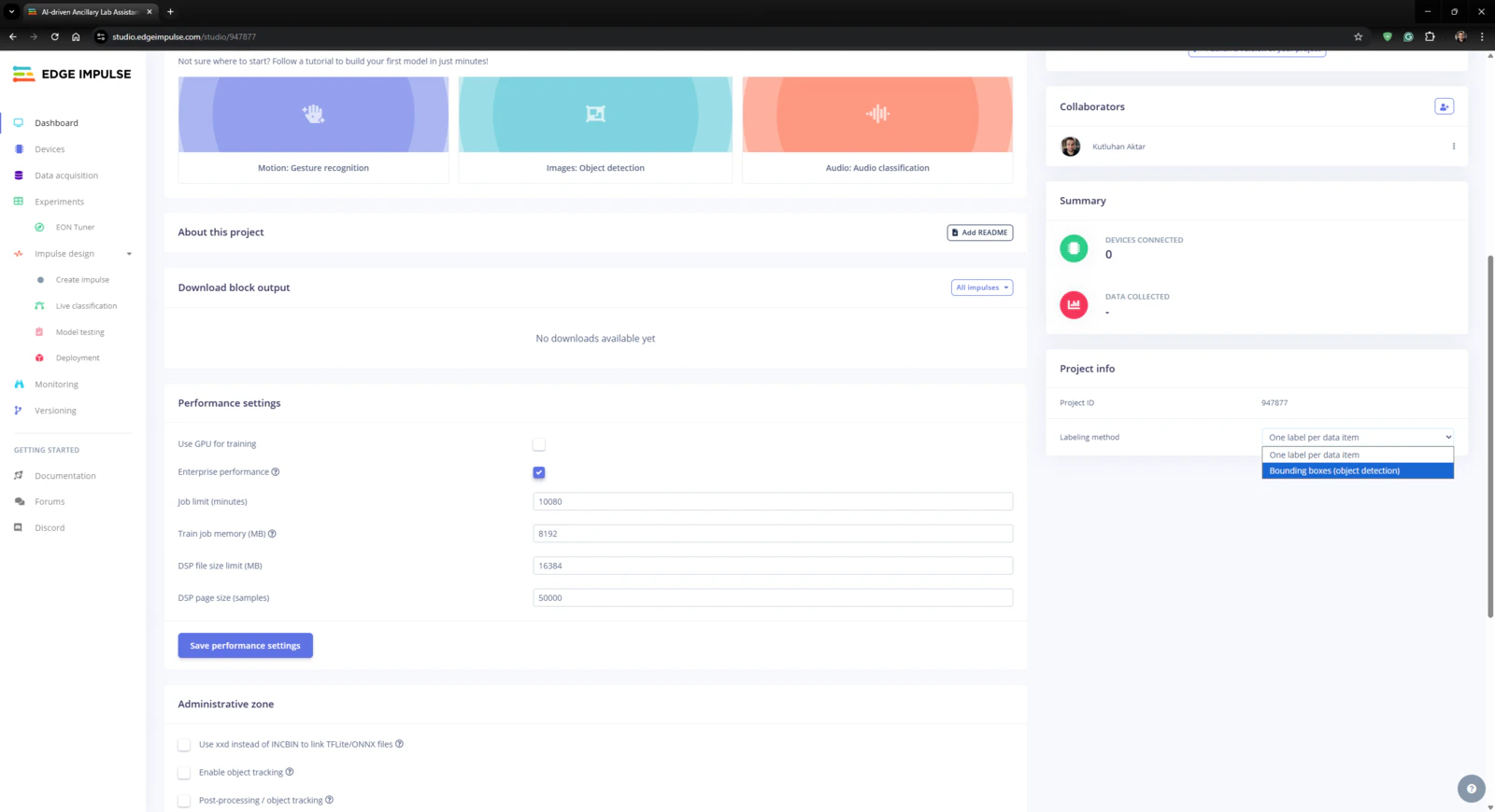
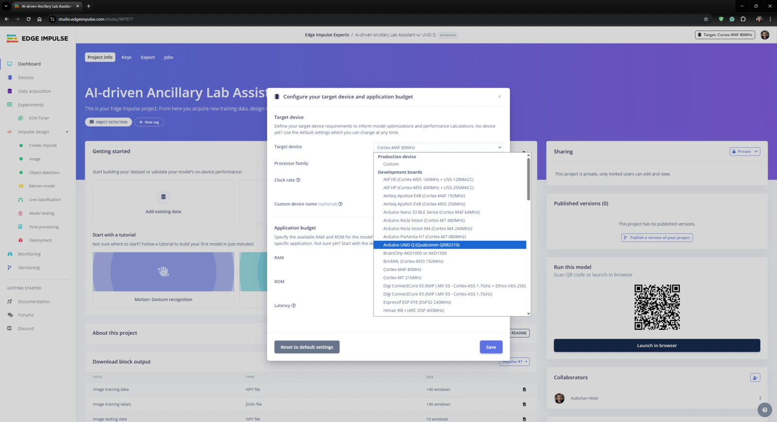
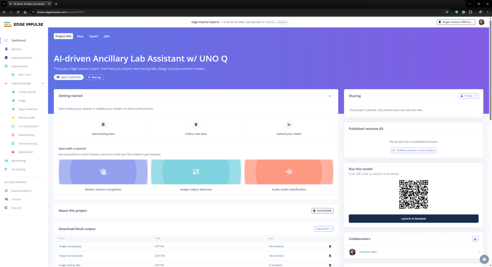
#️⃣ First, I created a new project on my Edge Impulse Enterprise account.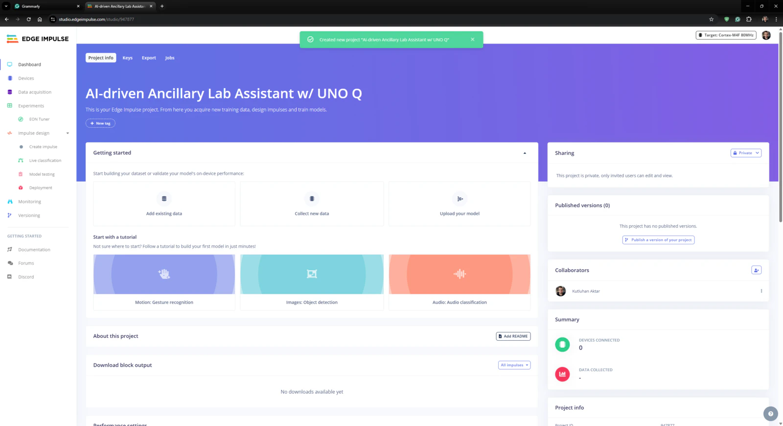
Step 4.2: Training the FOMO object detection model
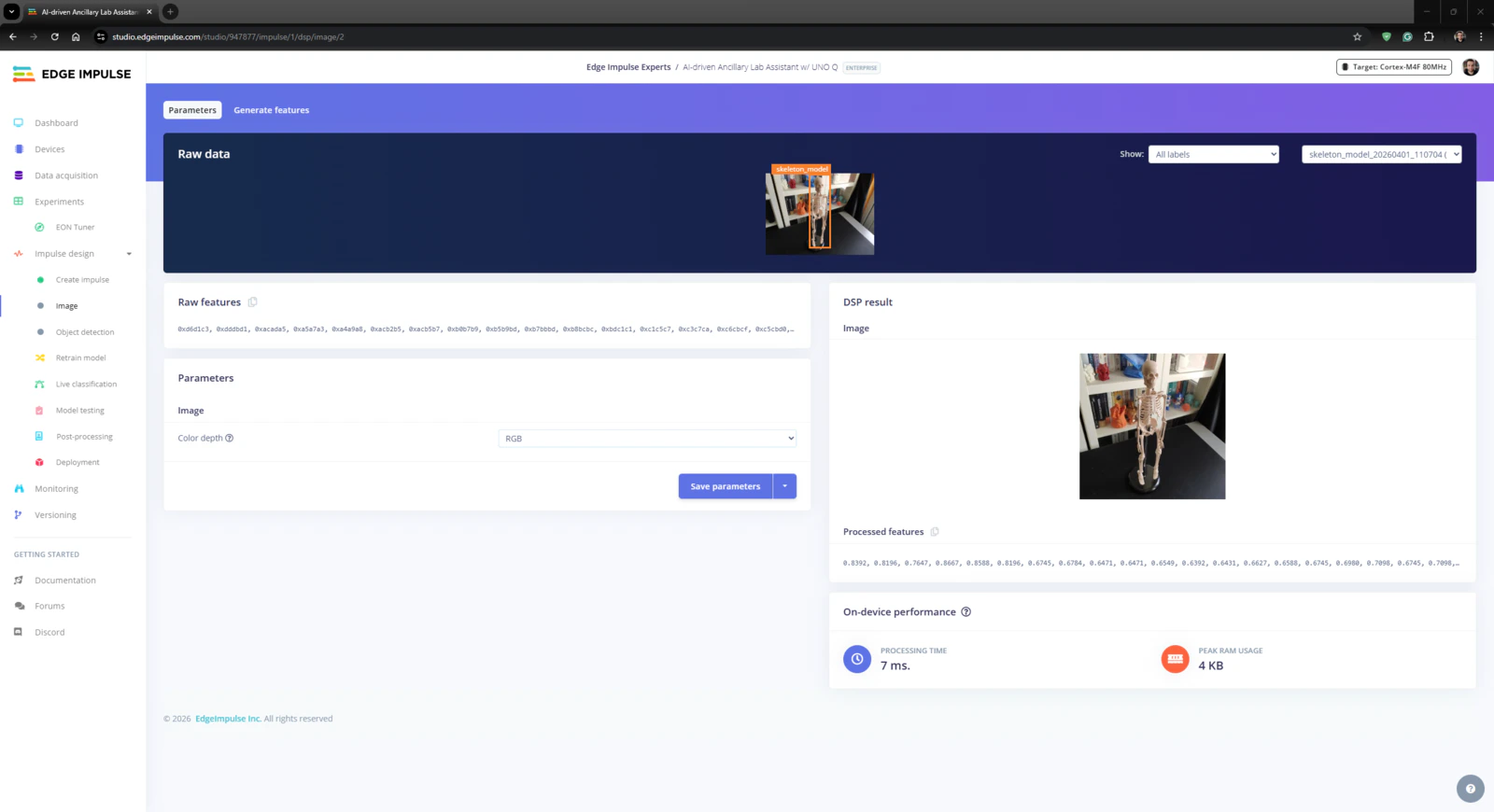
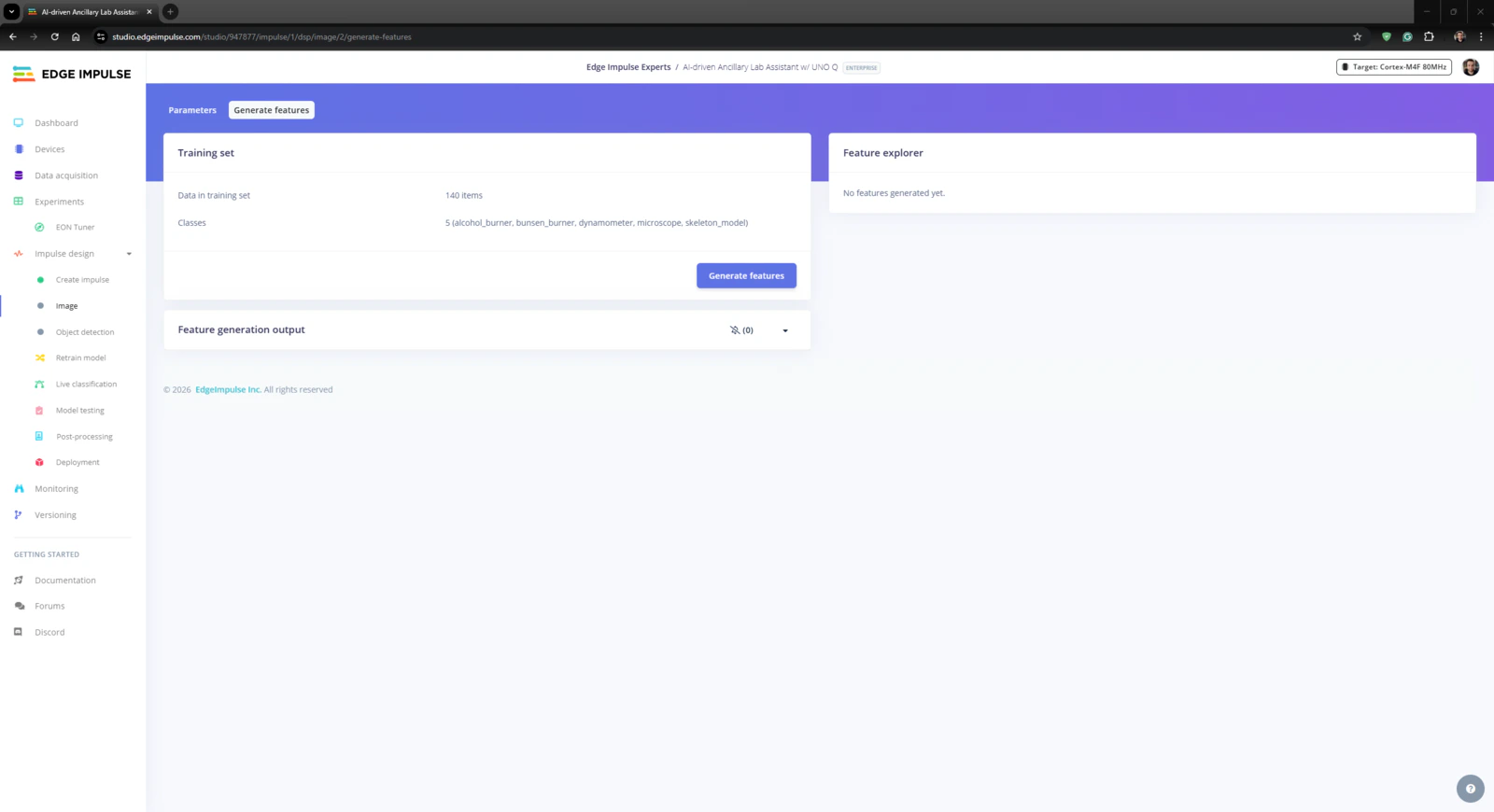
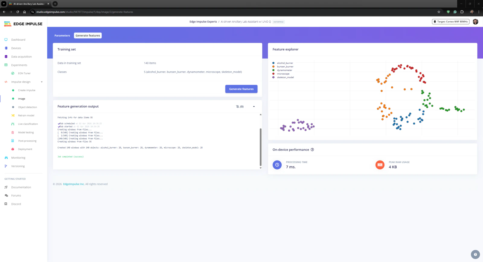
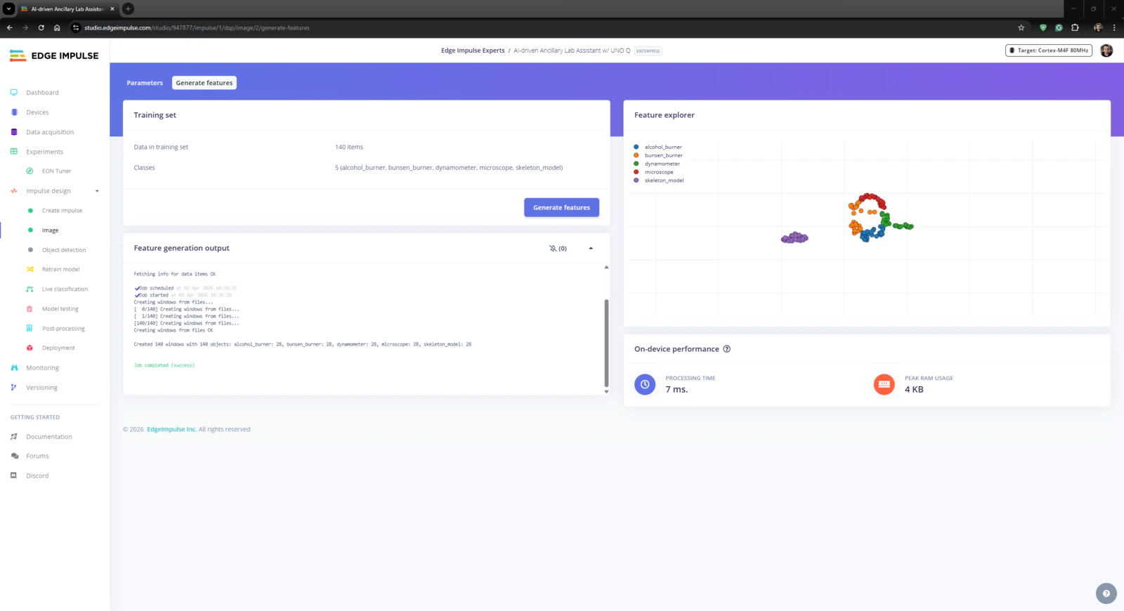
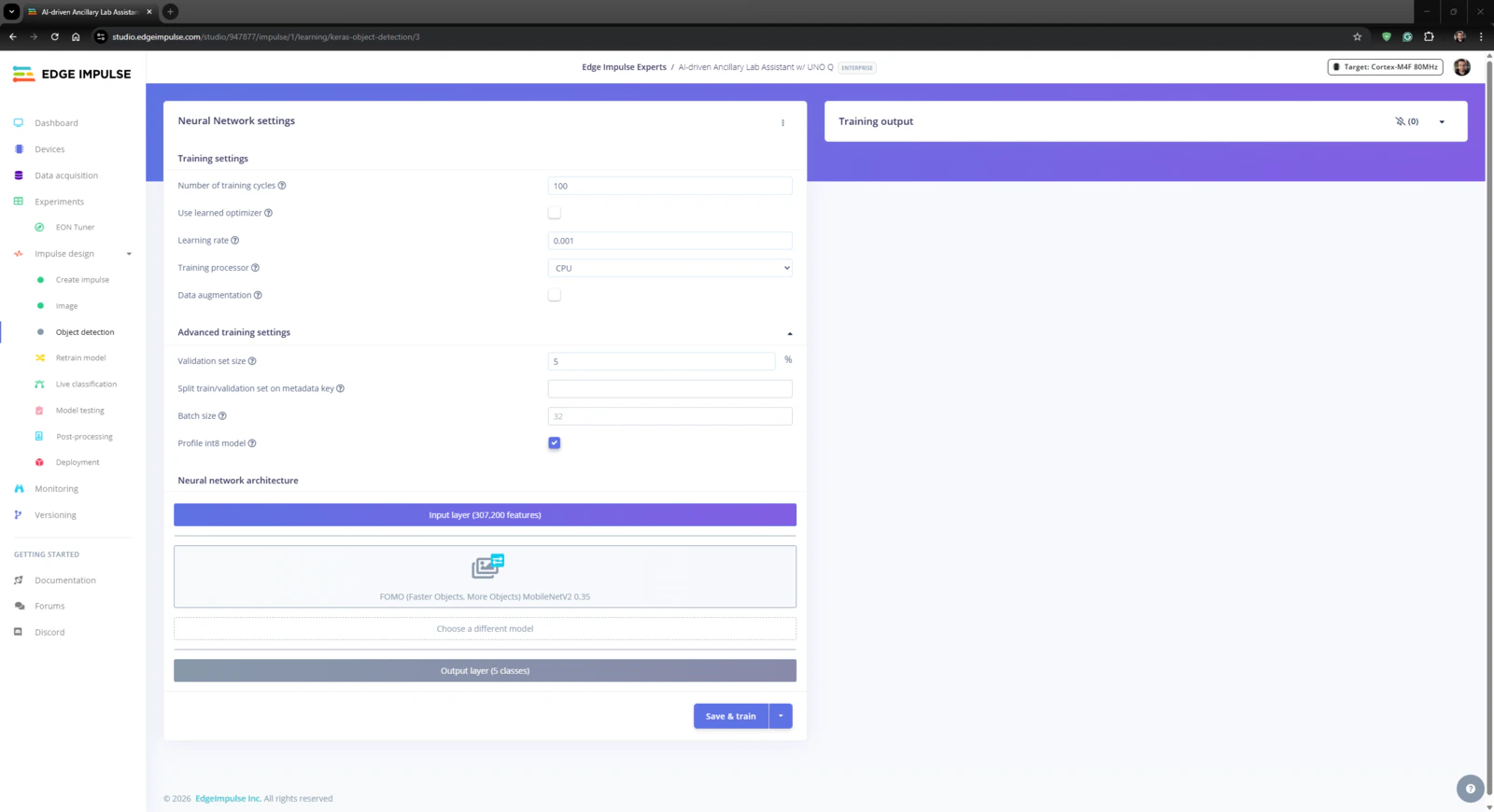
An impulse (an application developed and optimized by Edge Impulse) takes raw data, applies signal processing to extract features, and then utilizes a learning block to classify new data. For my application, I created the impulse by employing the Image processing block and the Object Detection (Images) learning block. Image processing block processes the passed raw image input as grayscale or RGB (optional) to produce a reliable features array. Object Detection (Images) learning block represents the officially supported machine learning algorithms performing object detection. #️⃣ First, I opened the Impulse design ➡ Create impulse section, set the model image resolution to 320 x 320, and selected the Fit shortest axis resize mode so as to scale (resize) the given image samples precisely. To complete the impulse creation, I clicked Save Impulse.
- Number of training cycles ➡ 100
- Learning rate ➡ 0.001
- Validation set size ➡ 5%
- FOMO (Faster Objects, More Objects) MobileNetV2 0.35
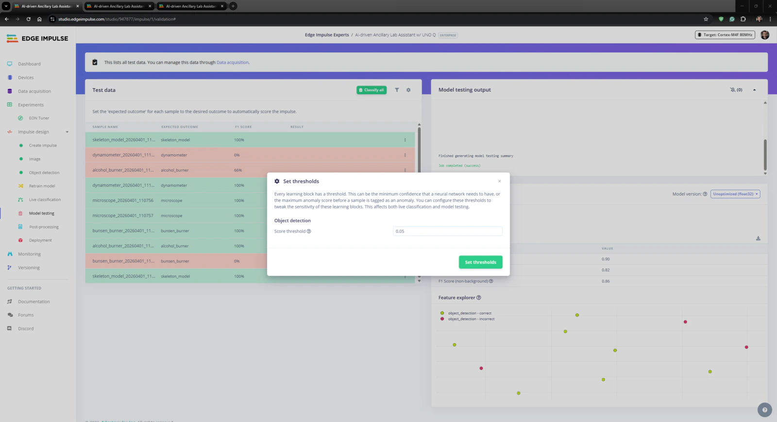
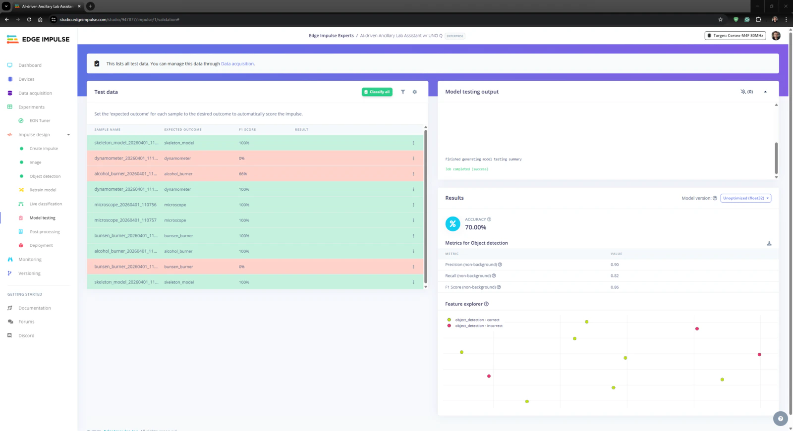
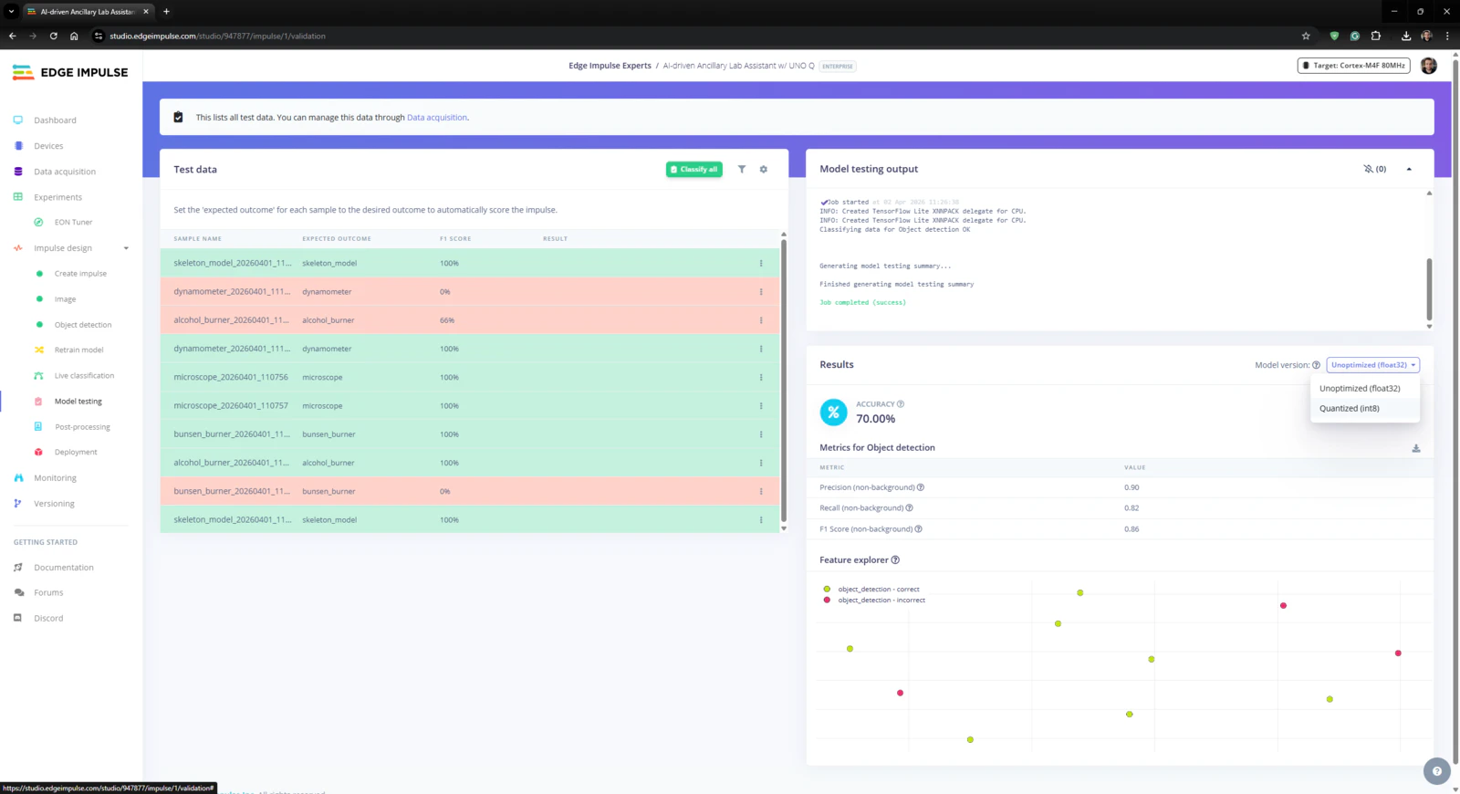
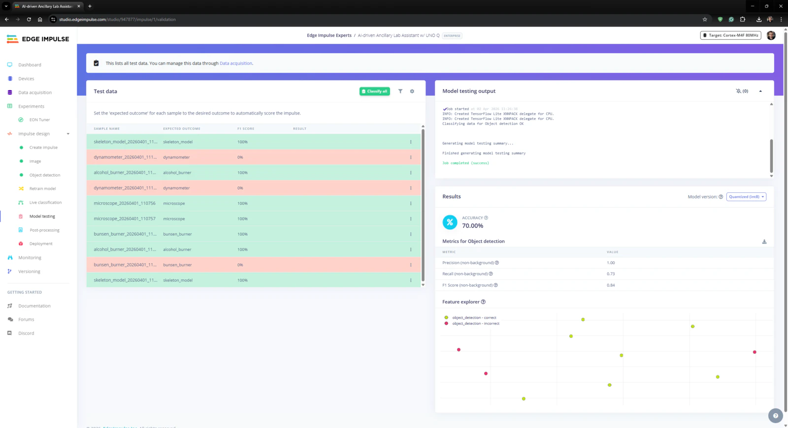
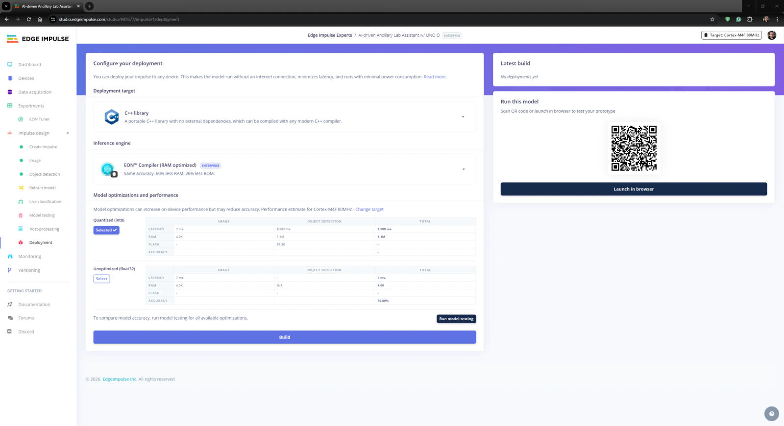
Step 4.3: Evaluating the model accuracy and deploying the validated model
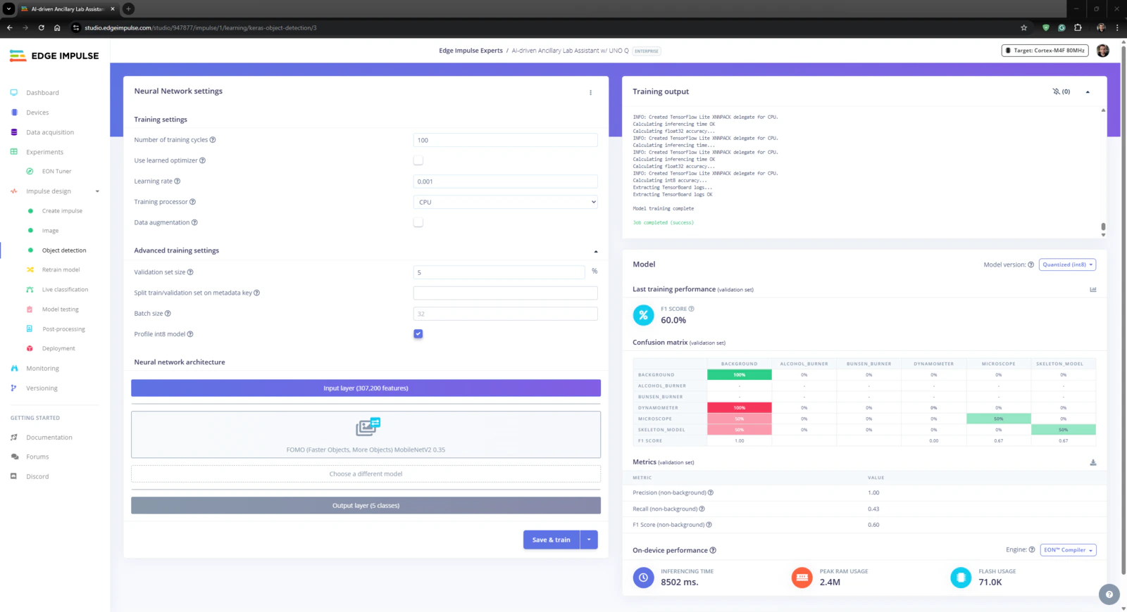
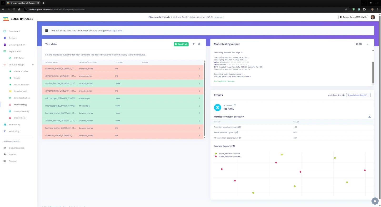
#️⃣ First, to obtain the validation score of the trained model based on the provided testing samples, I navigated to the Impulse design ➡ Model testing section and clicked Classify all. #️⃣ Based on the initial F1 score, I started to rigorously experiment with the confidence score threshold value to pinpoint the optimum range for the real-world conditions. #️⃣ After experimenting with the Unoptimized (float32) and Quantized (int8) model variants, I obtained the model accuracy (F1 score - precision) up to 70.0% and estimated the sweet spot for the threshold range.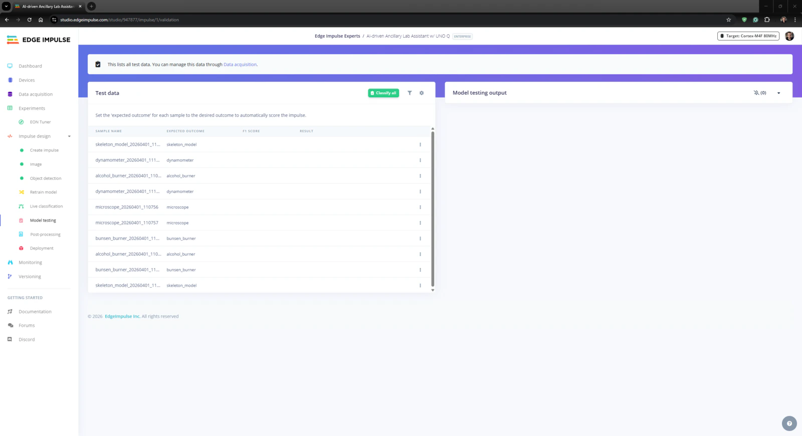
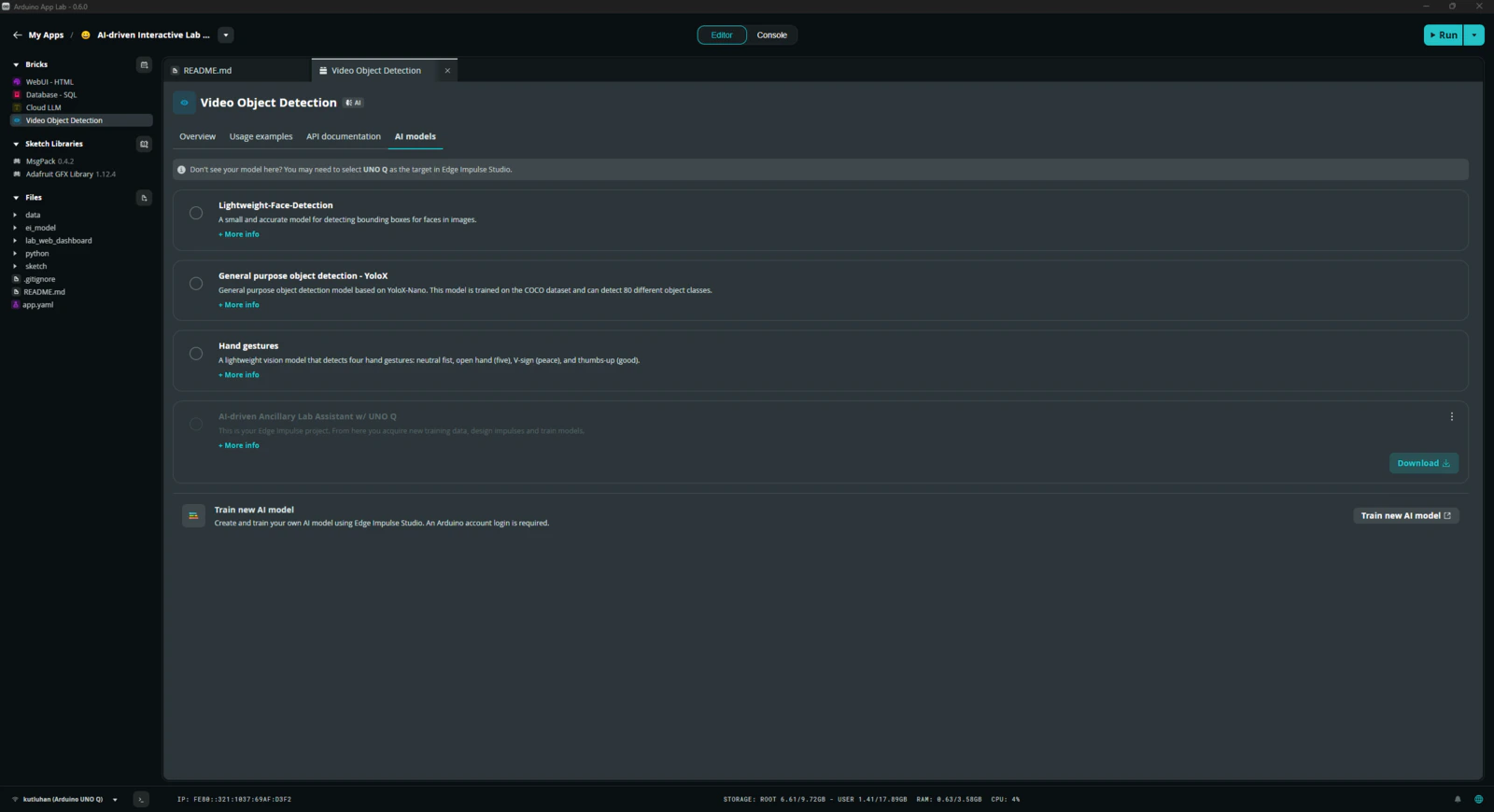
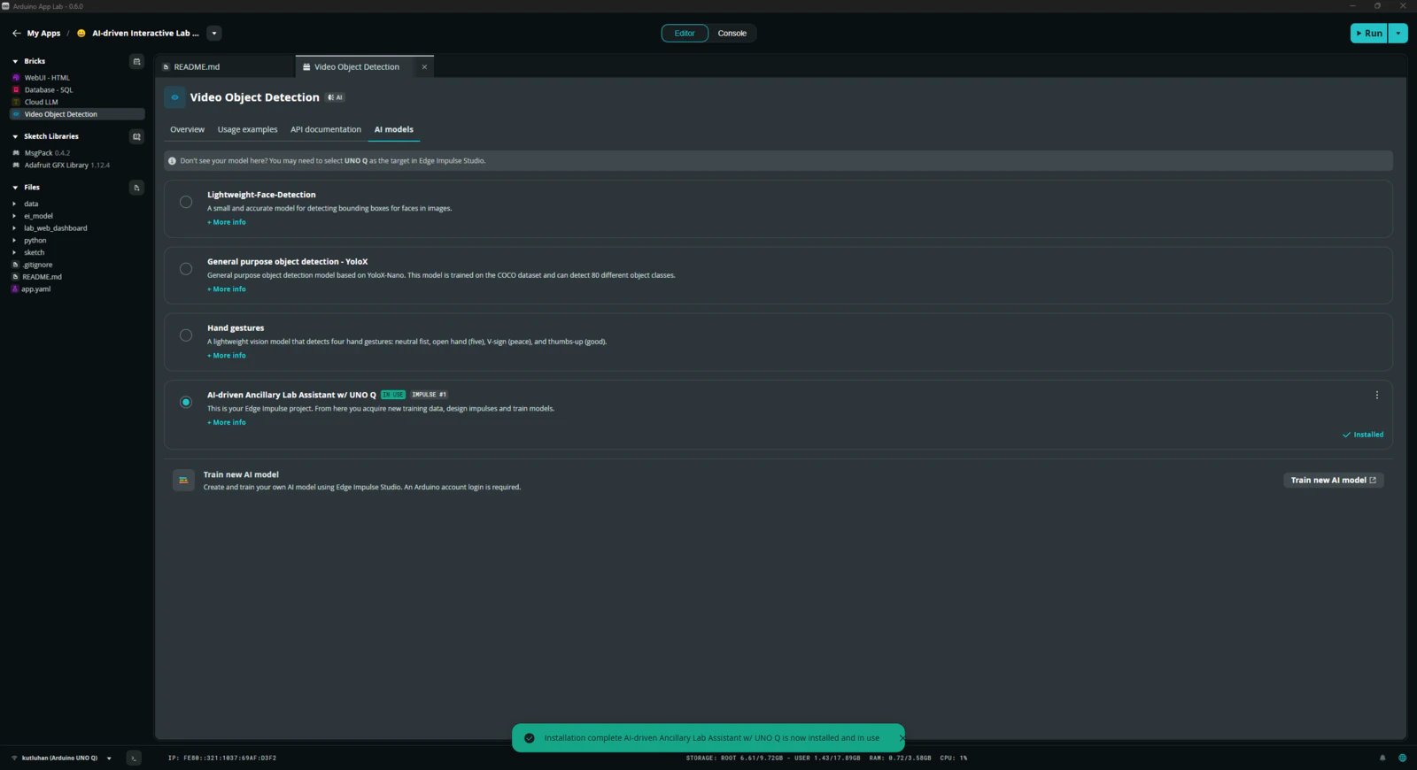
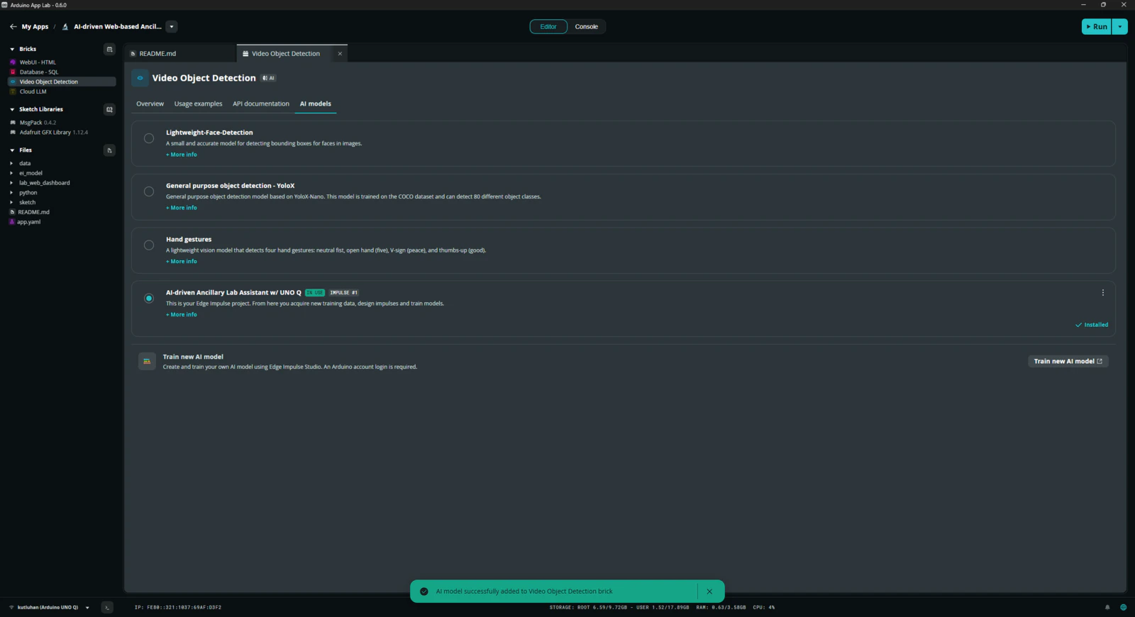
Step 5: Adding and adjusting the necessary Bricks to develop a feature-rich lab assistant application on the App Lab
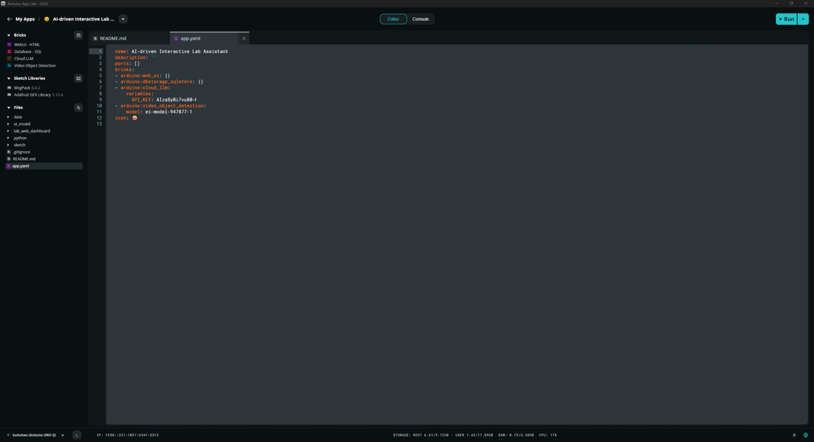
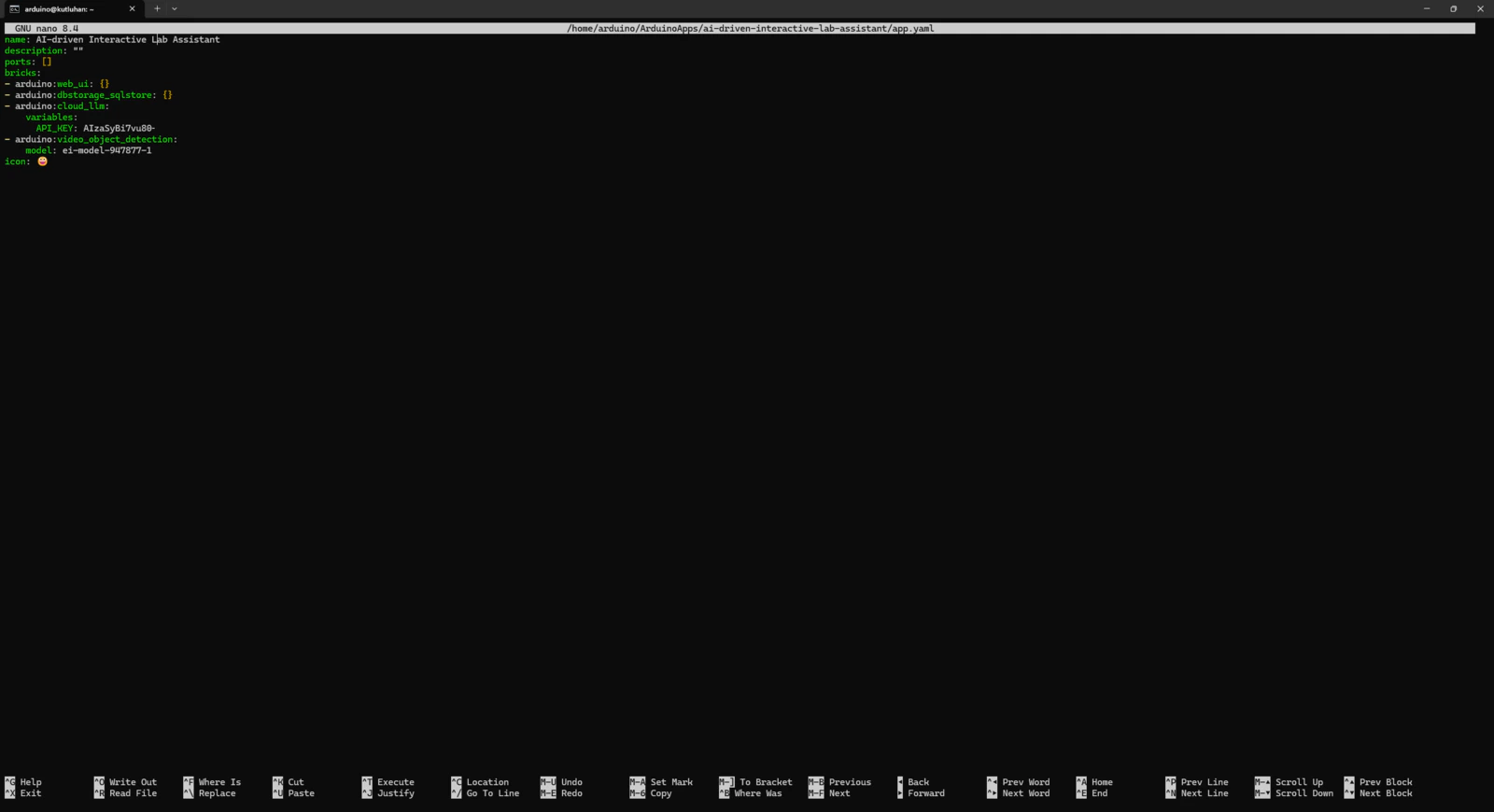
As mentioned earlier, the Arduino App Lab provides pre-configured services and Docker containers, Bricks, to add various features to a custom App Lab application. Each Brick provides a specific set of capabilities that are executed by the Qualcomm MPU (Linux) and can be accessed by the Python script (backend) of the application via the built-in high-level APIs. To develop my lab assistant App Lab application, I utilized these Bricks without using any additional third-party APIs or services: #️⃣ To enable the Cloud LLM Brick to utilize Google Gemini, open its Brick configuration section and register the previously acquired Gemini API key.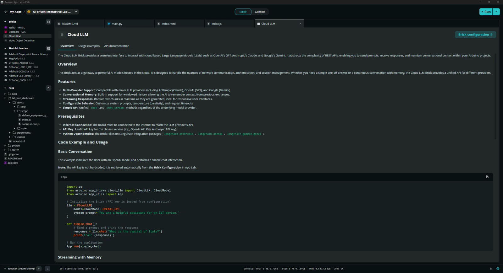
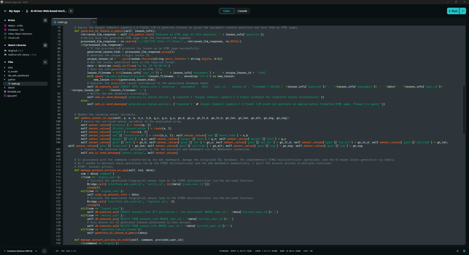
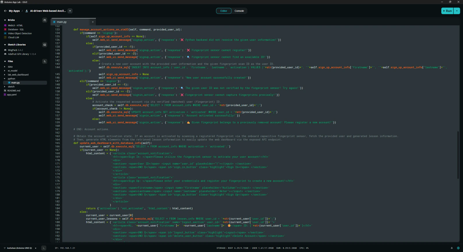
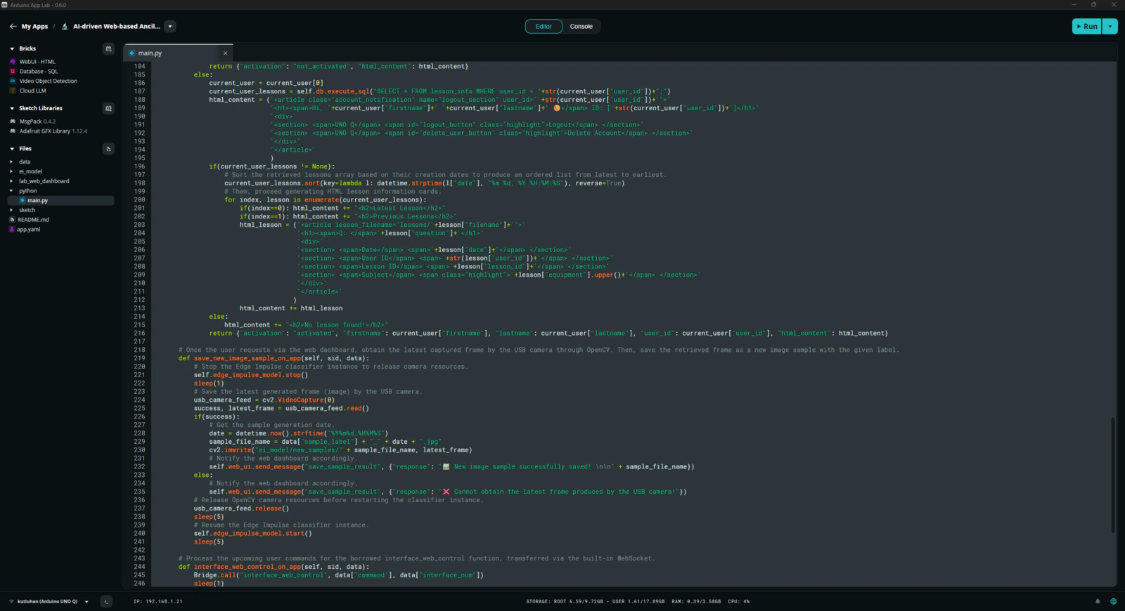
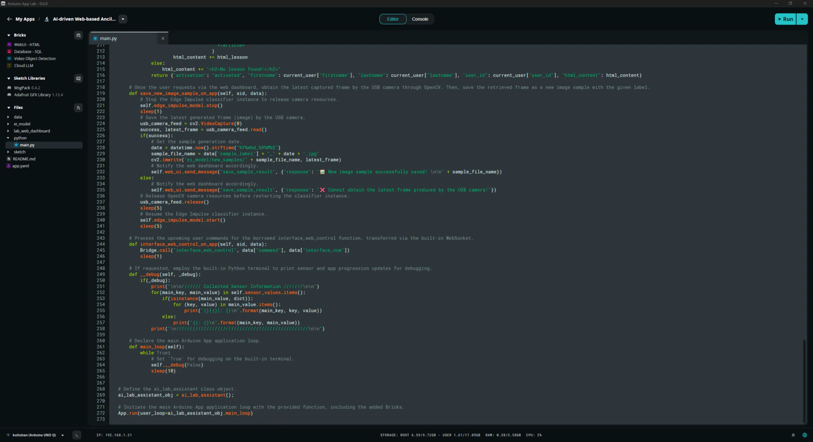
Step 6: Programming the Python script (backend) executed by the Qualcomm QRB2210 microprocessor (MPU)
According to the App Lab application structure, this Python script behaves as the application backend and manages all data transfer processes, Brick features, and interconnected services. 📁 main.py ⭐ Include the required system and high-level Brick libraries.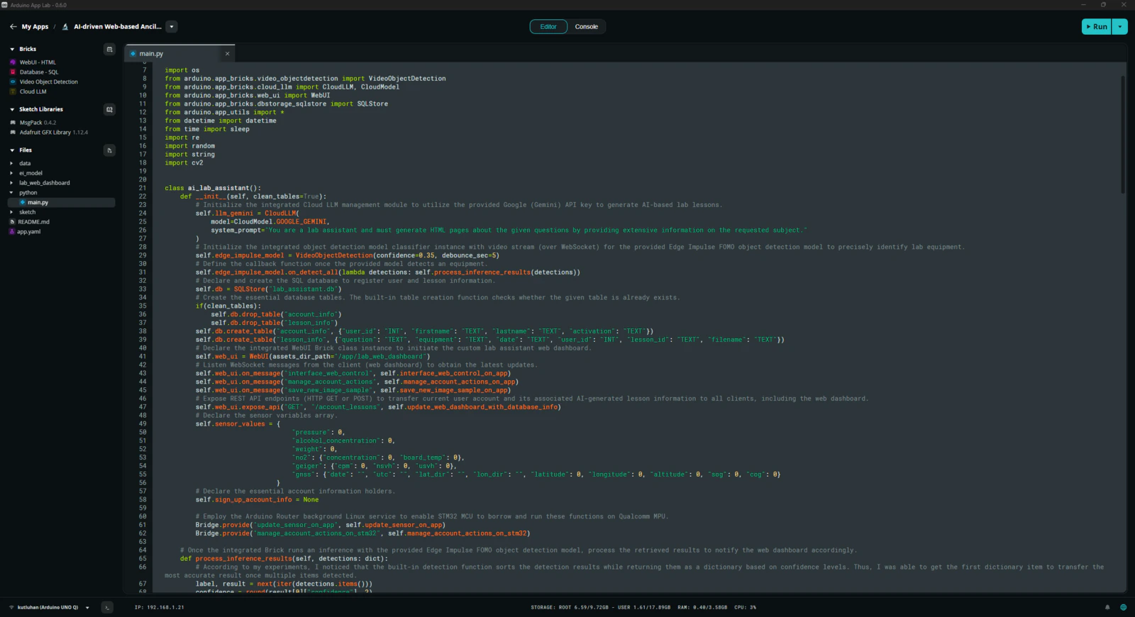
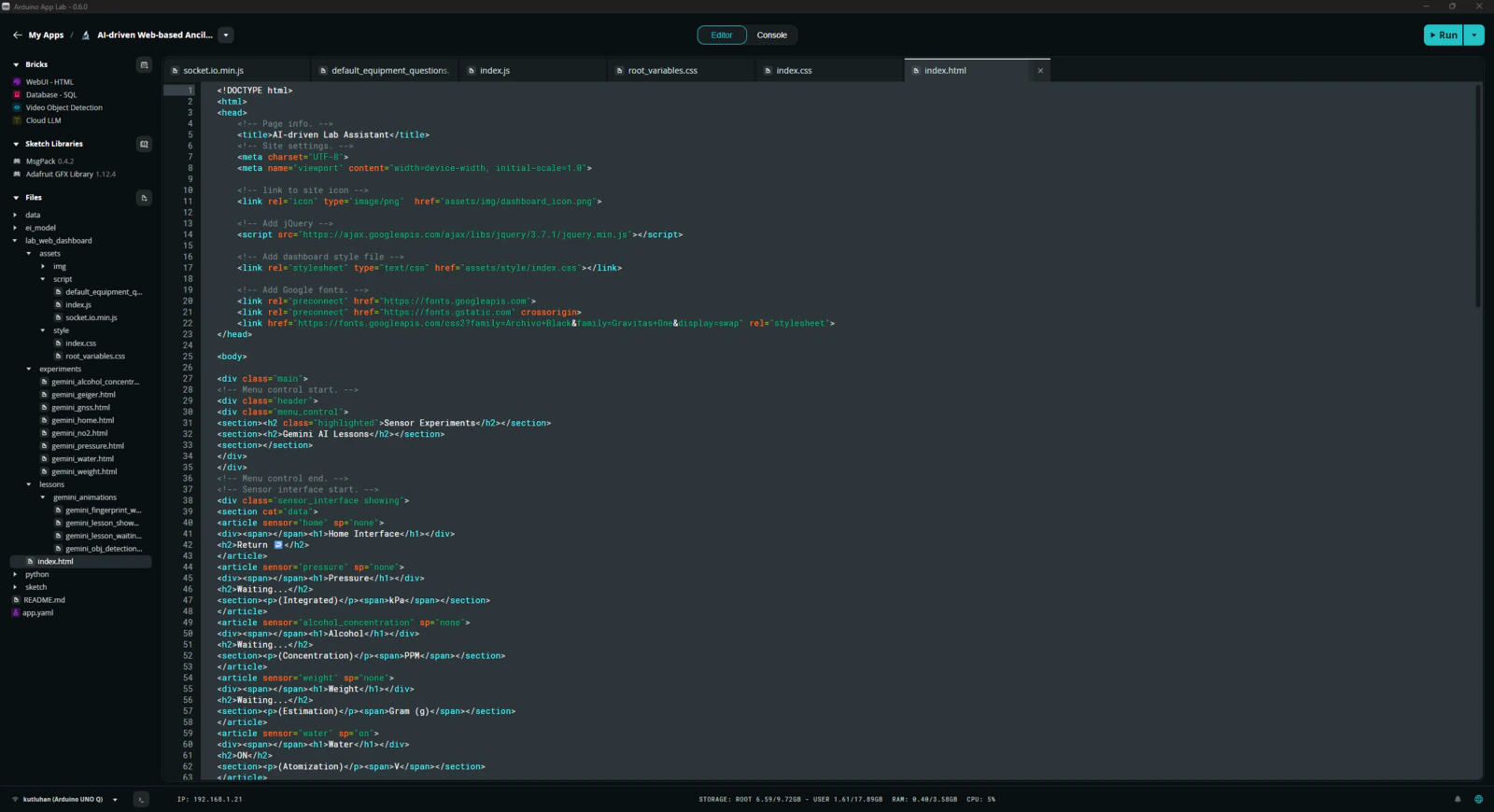
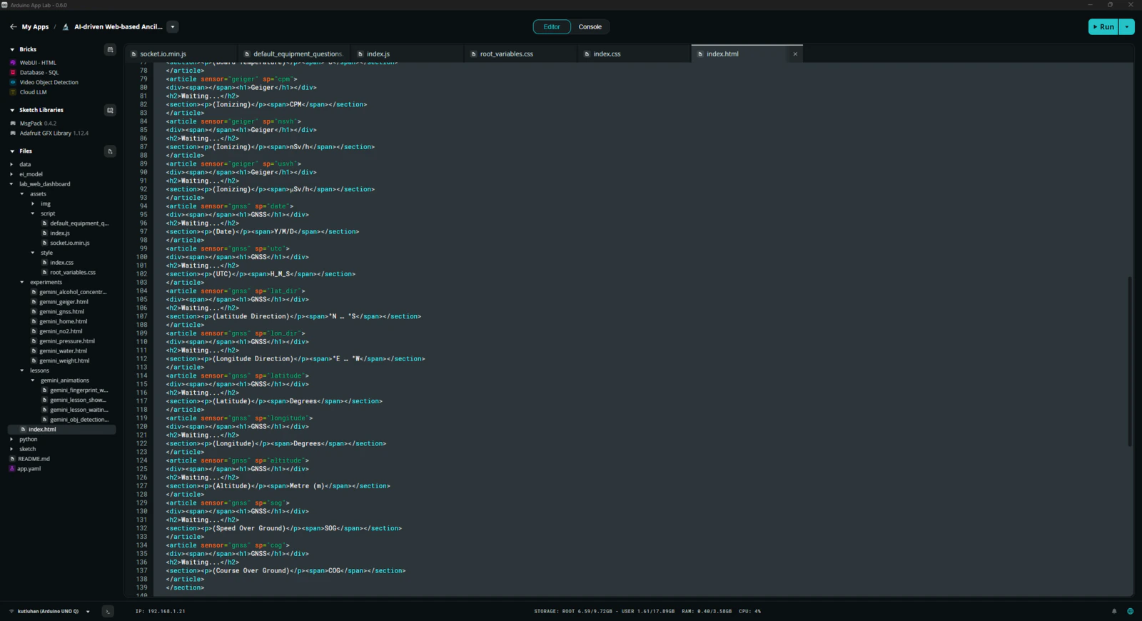
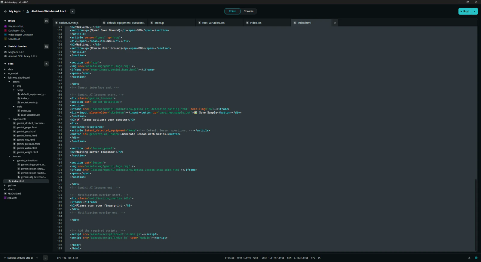
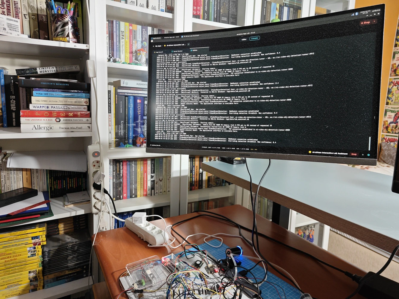
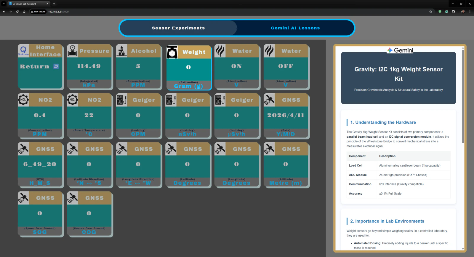
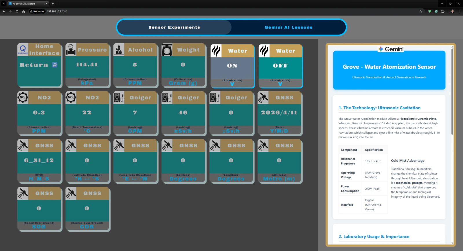
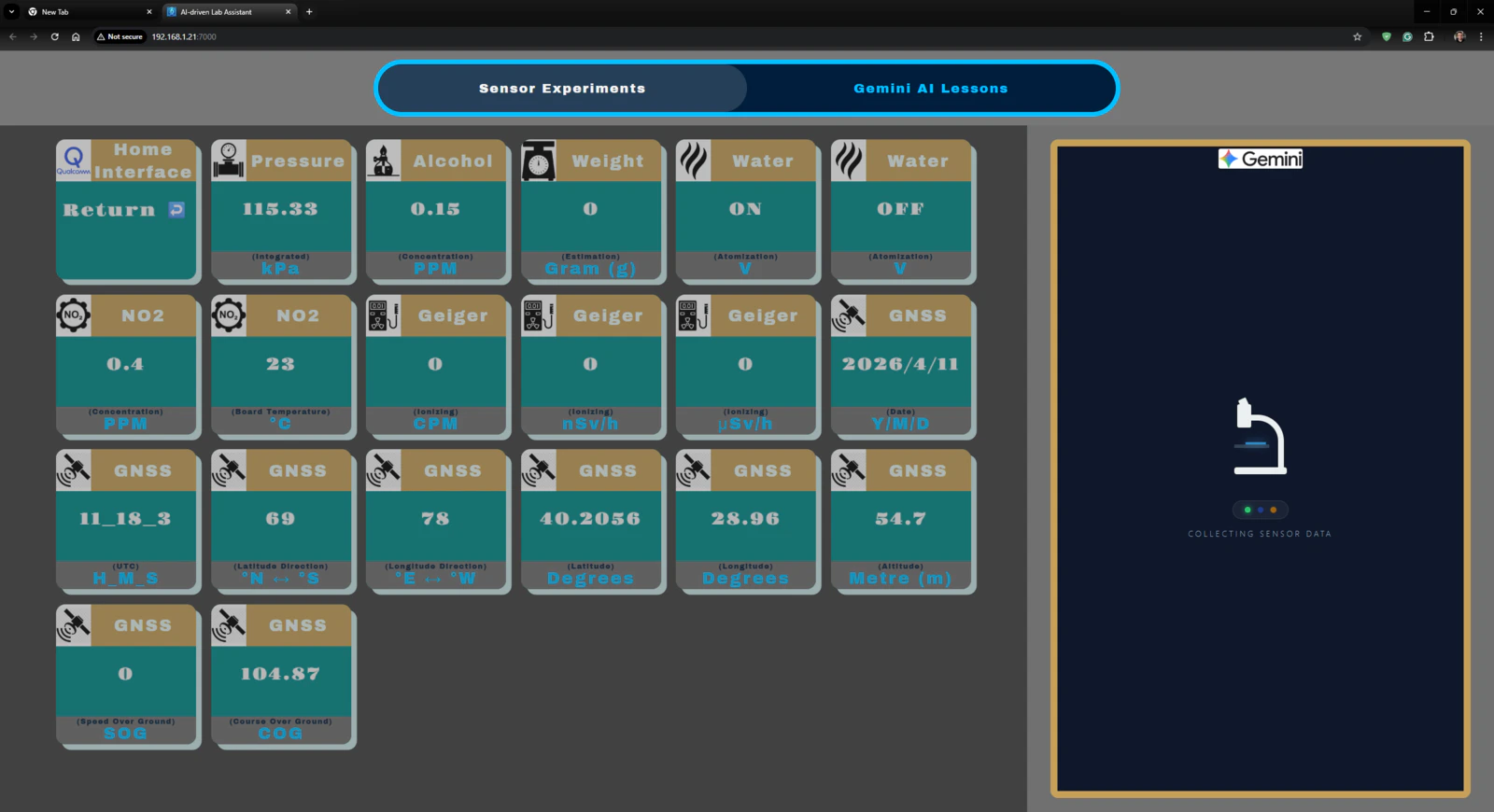
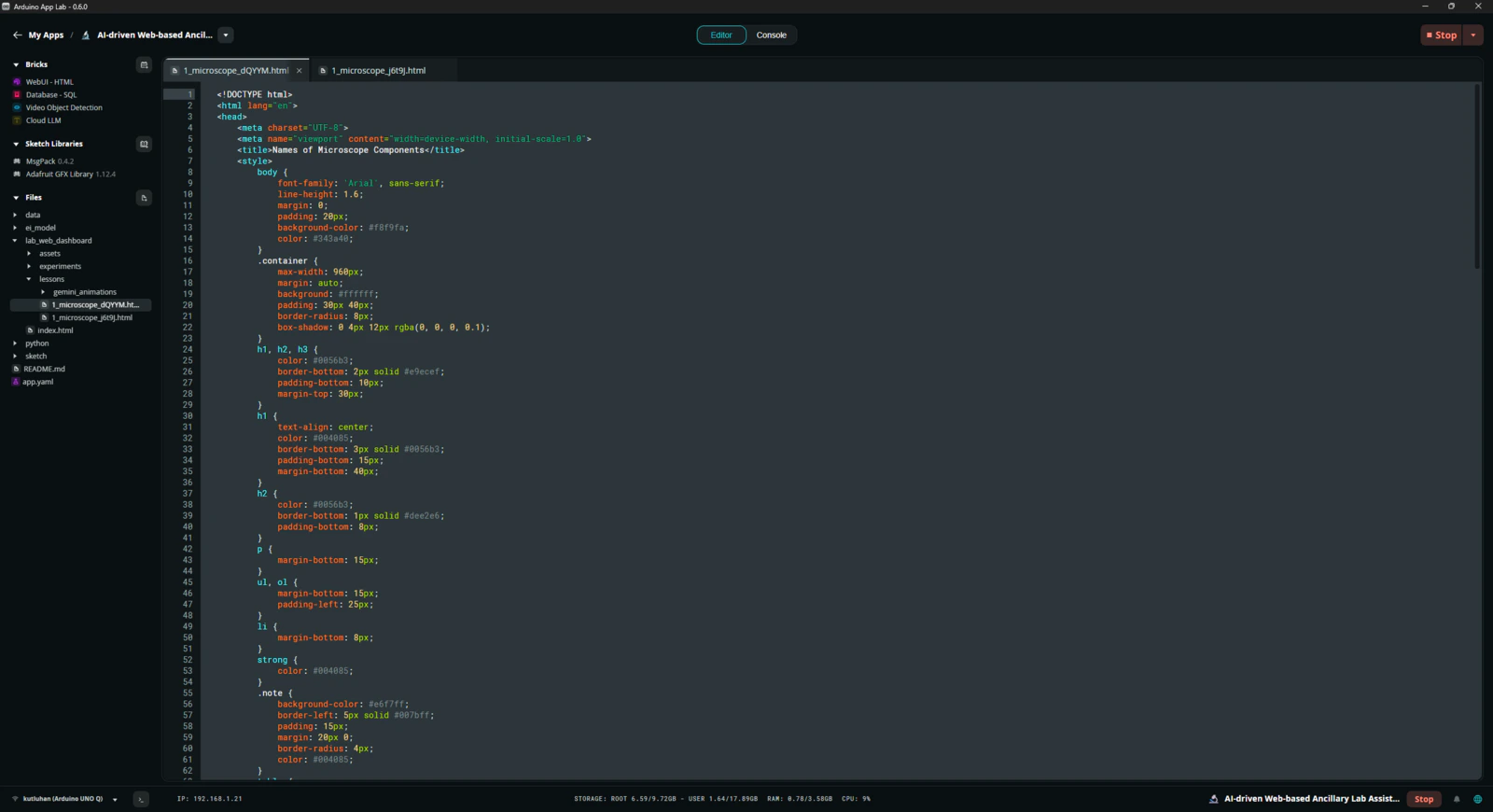
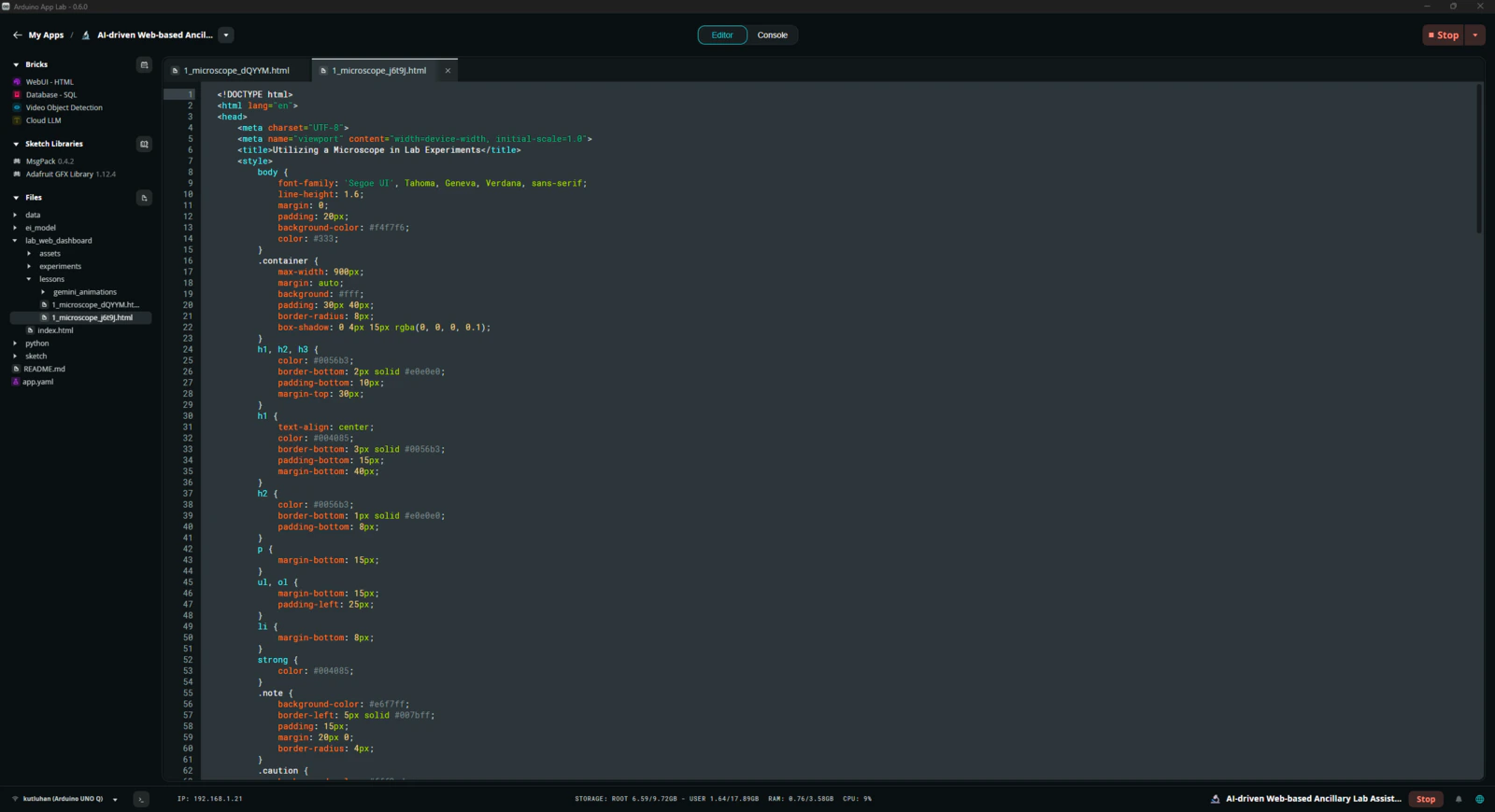
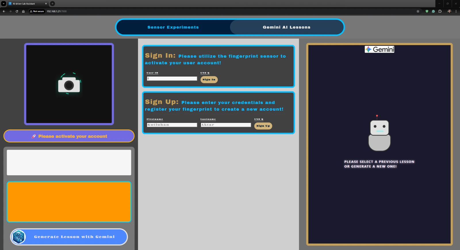
Step 7: Developing a full-fledged lab assistant web dashboard hosted directly by the Arduino App Lab
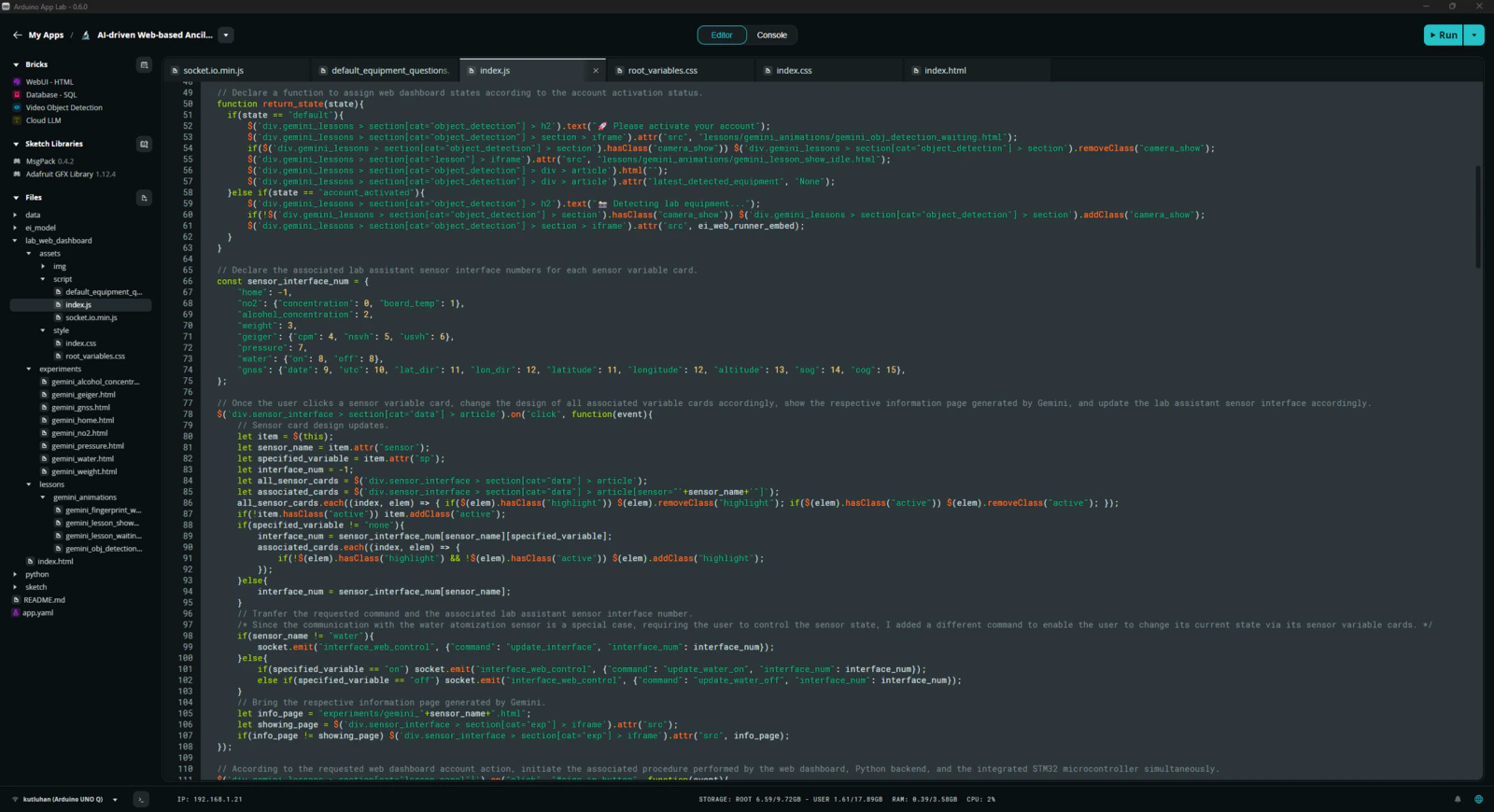
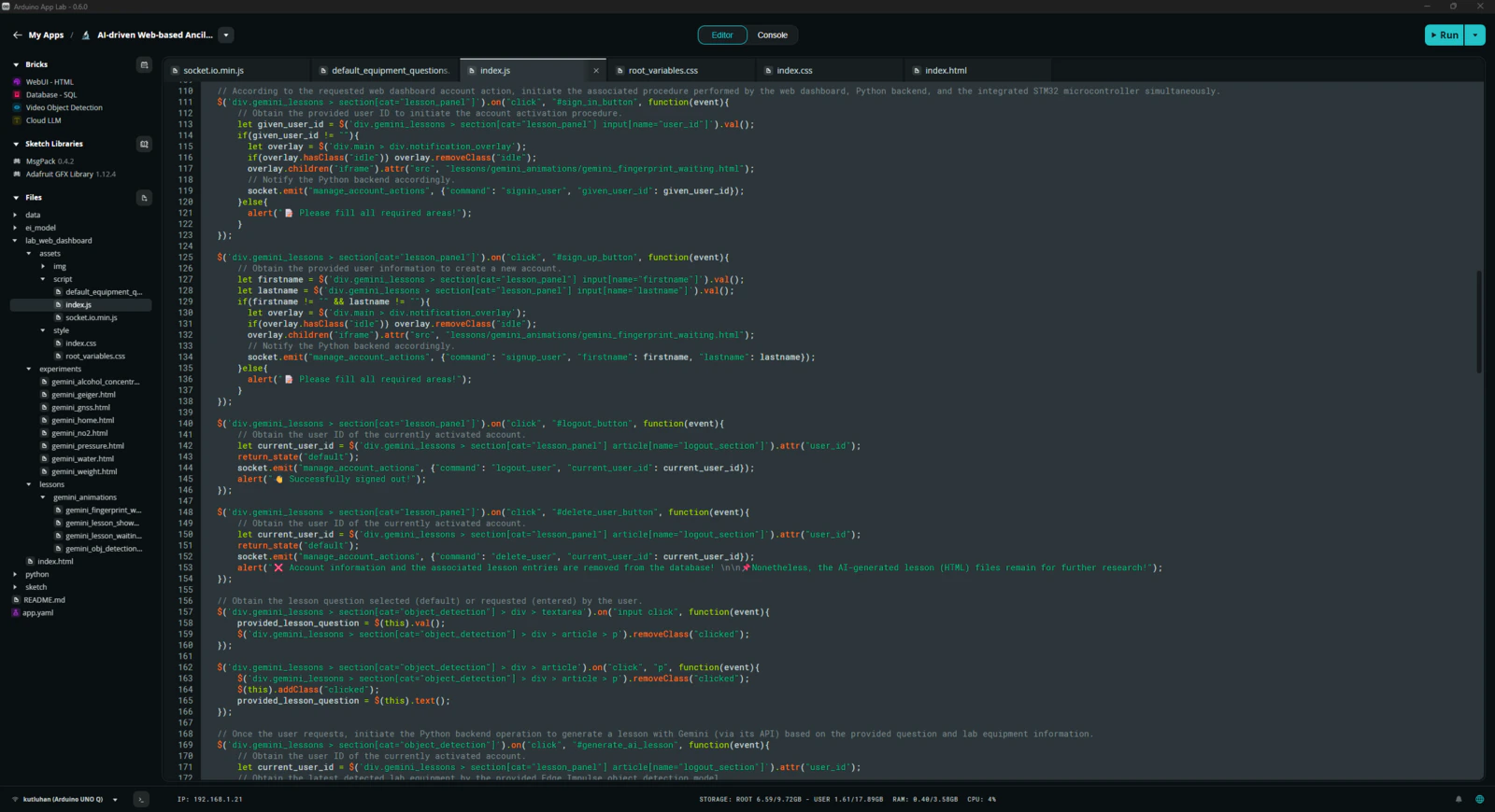
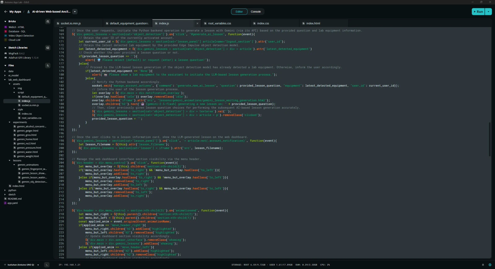
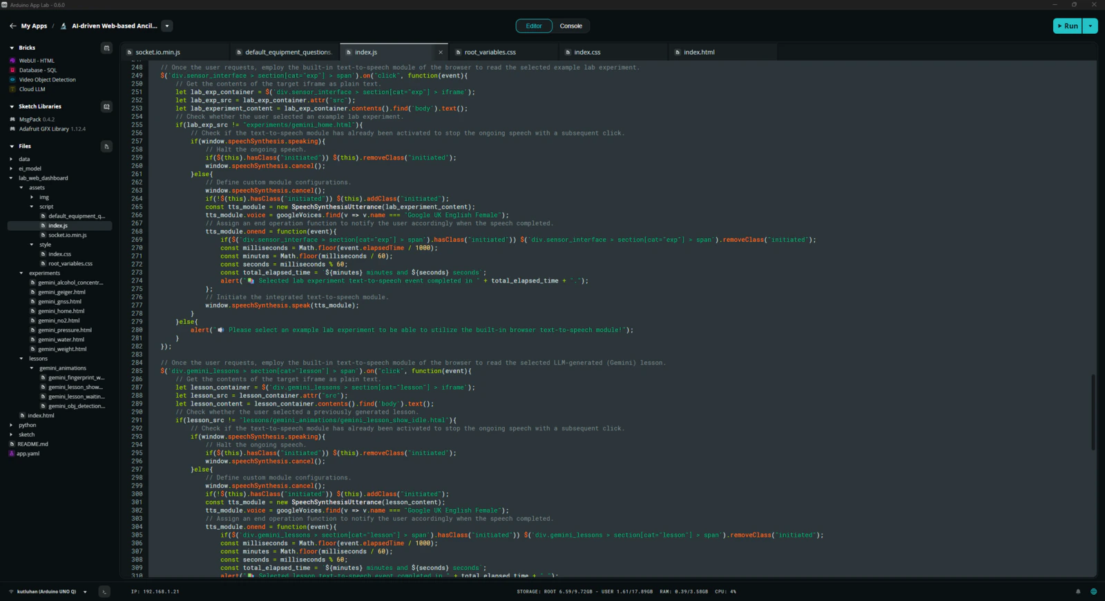
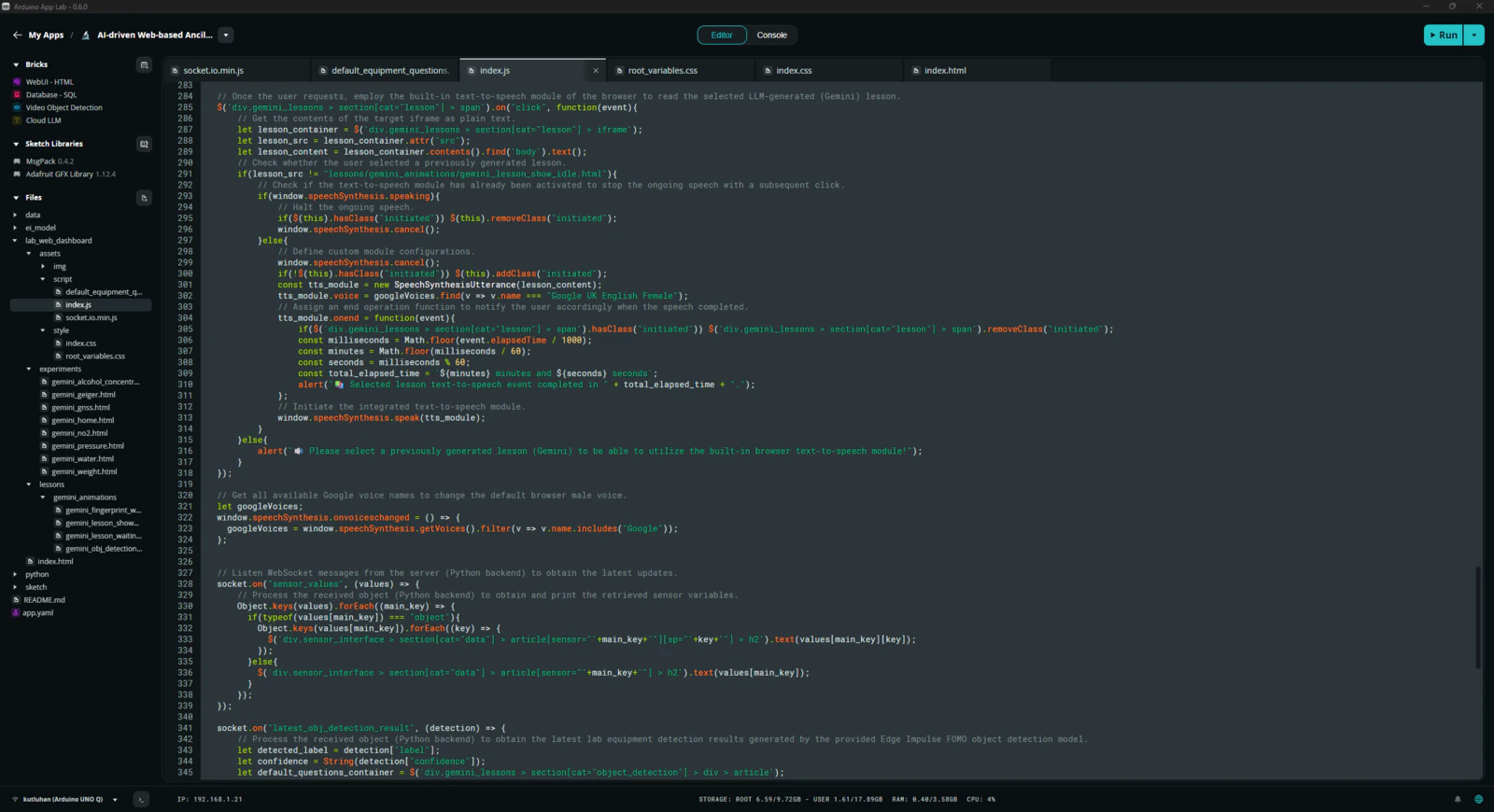
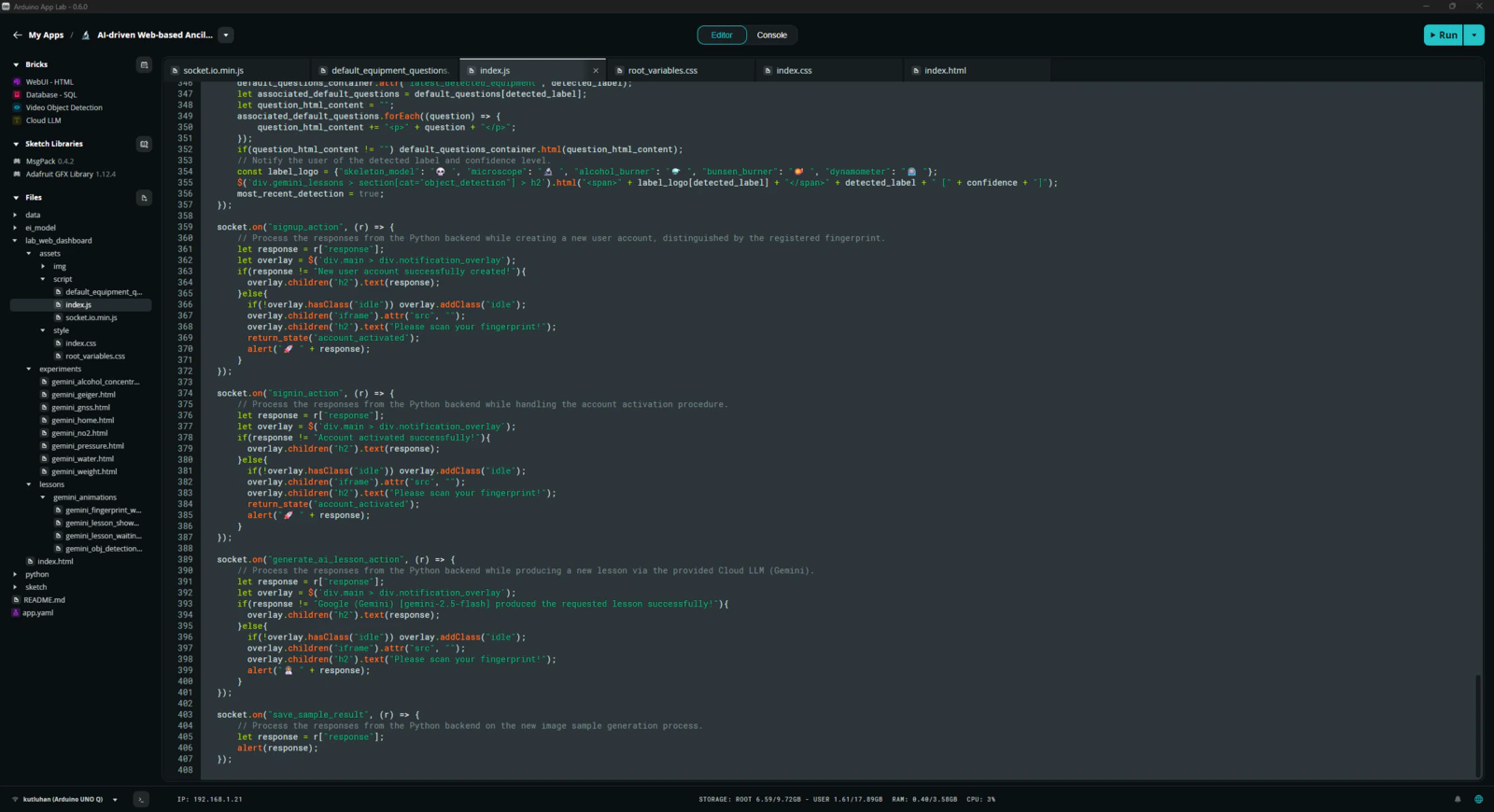
As mentioned earlier, the built-in WebUI Brick handles hosting of the provided web user interface. Thus, I only needed to develop the lab assistant web dashboard in compliance with the integrated WebSocket and let the Arduino App Lab host the dashboard automatically. Please refer to the project GitHub repository to inspect all of the lab assistant web dashboard code files. 📁 socket.io.min.js #️⃣ This script includes the necessary functions to communicate with the Python backend via WebSocket.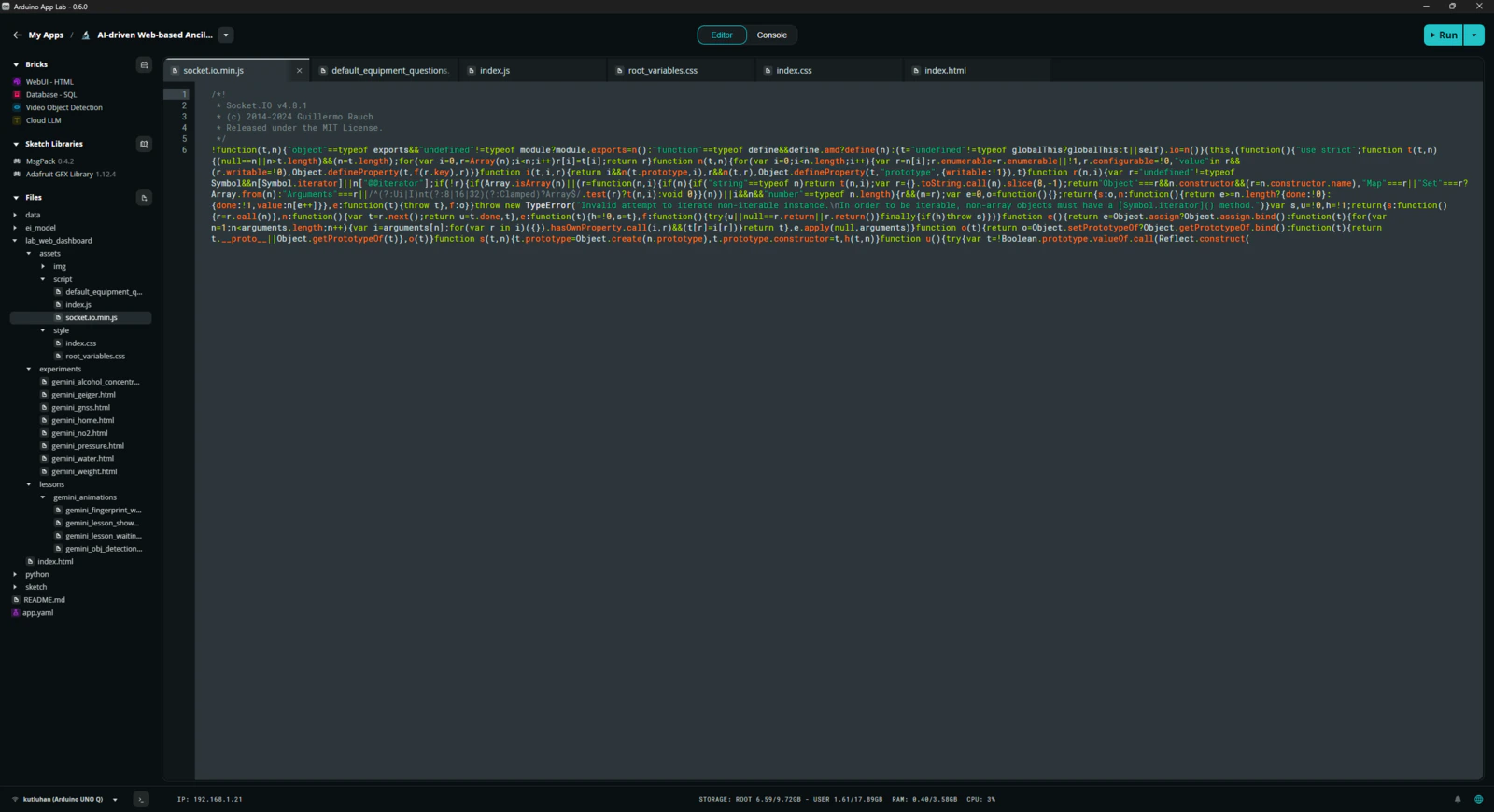
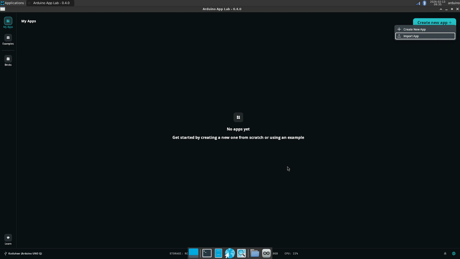
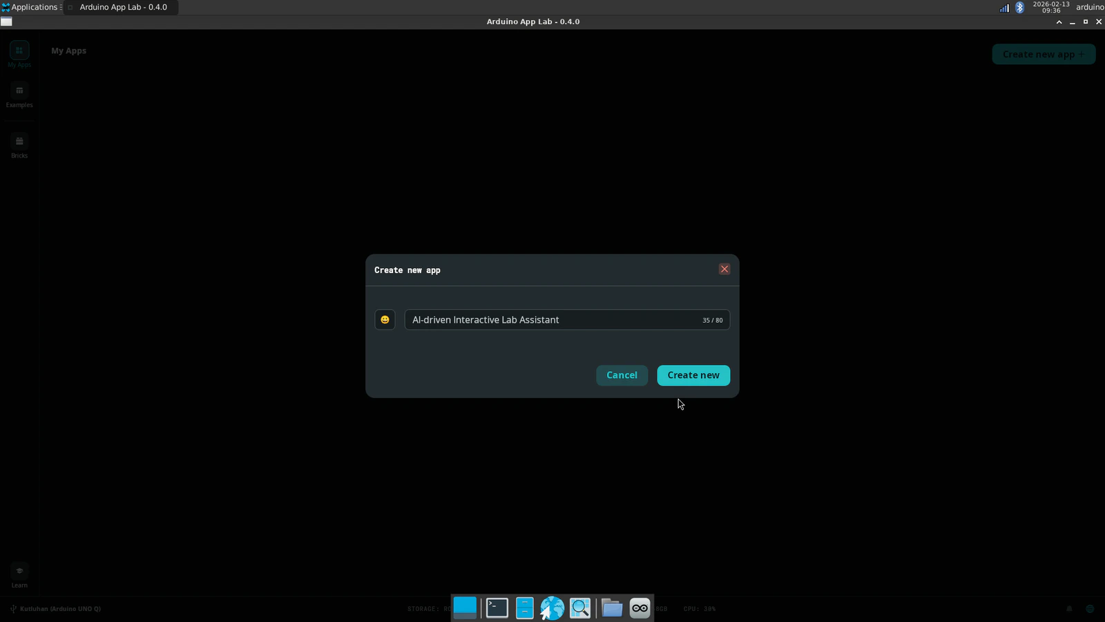
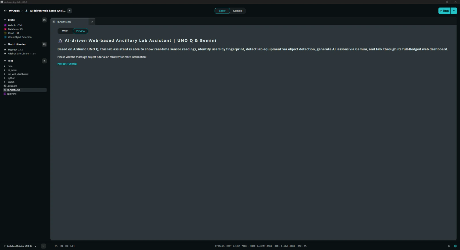
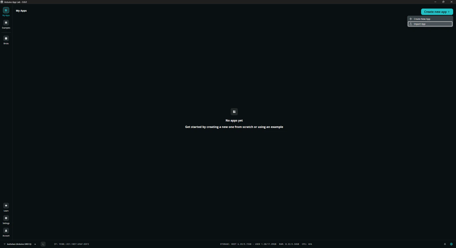
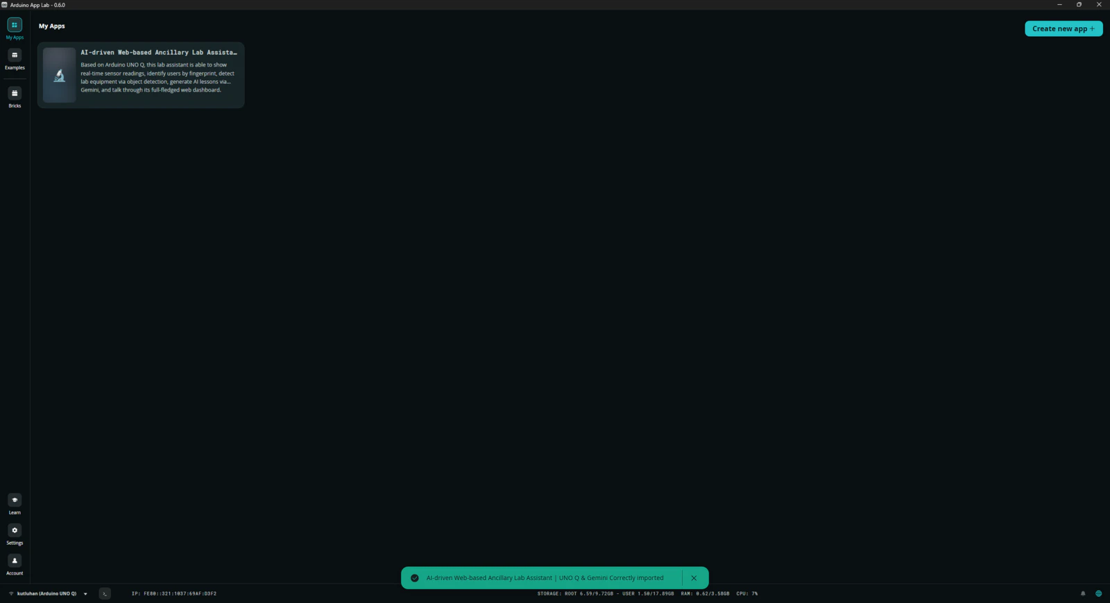
Step 7.1: Ensuring the lab assistant App Lab application operates as anticipated to enable easy importing for further research cases
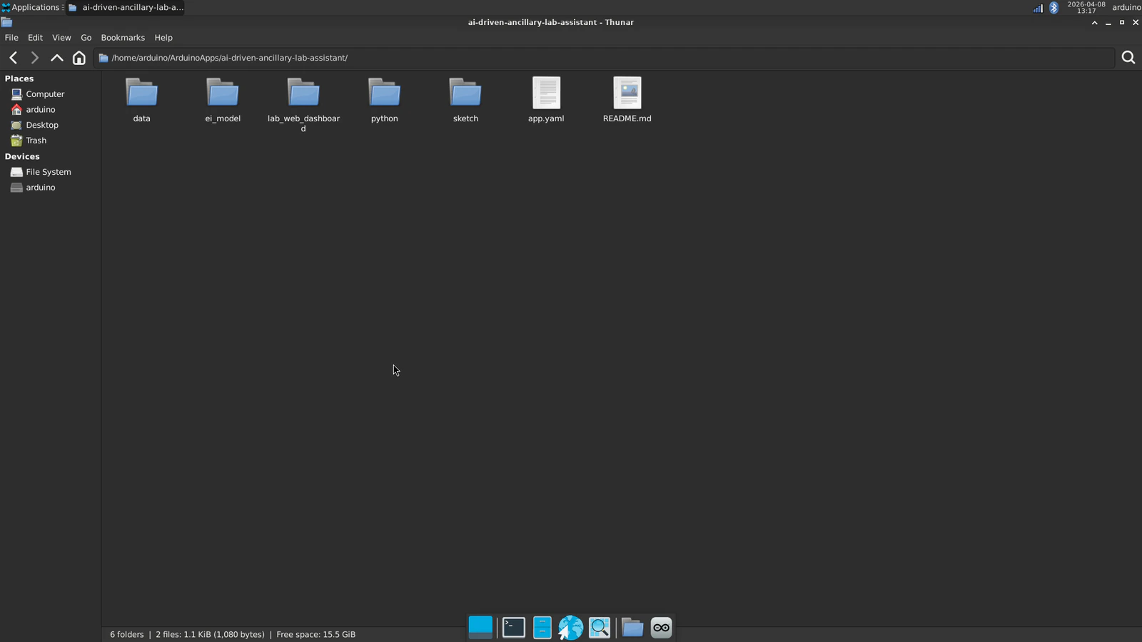
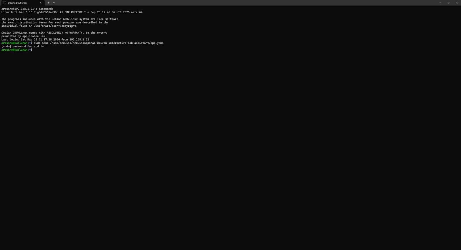
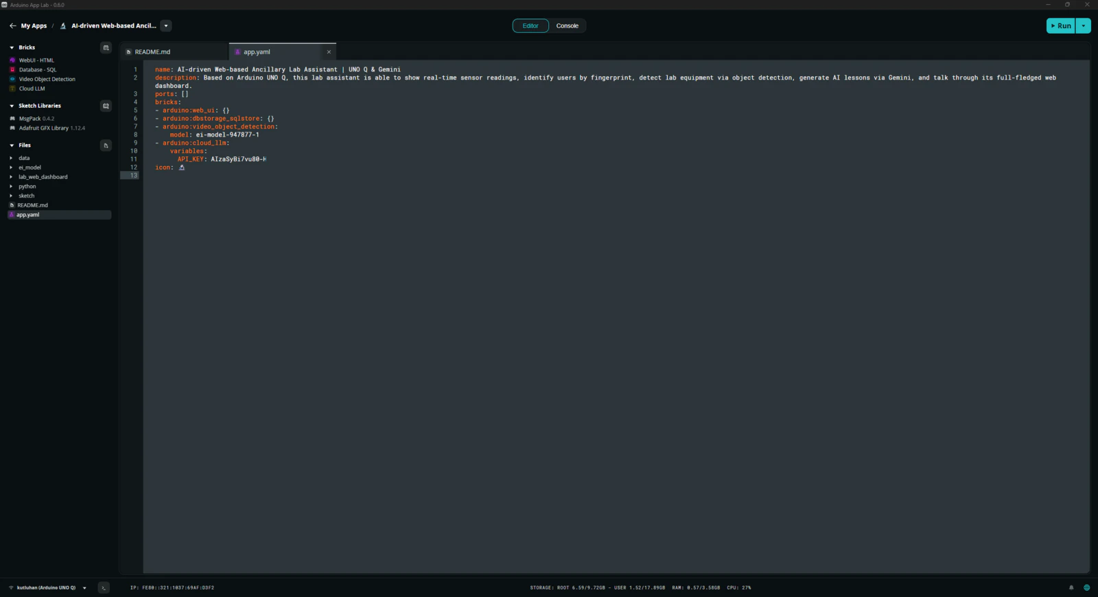
After completing the development of the lab assistant App Lab application, I rechecked all code files, assets, and configurations to make sure the application was ready for exporting without any errors. 📚 The finalized lab assistant App Lab application directory structure (alphabetically) is as follows: Please refer to the project GitHub repository to review all files.- /data
-
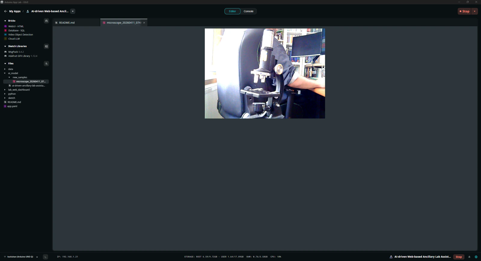
/ei_model
- /new_samples
- ai-driven-ancillary-lab-assistant-w-uno-q-linux-aarch64-v1.eim
-
/lab_web_dashboard
-
/assets
- /img
-
/script
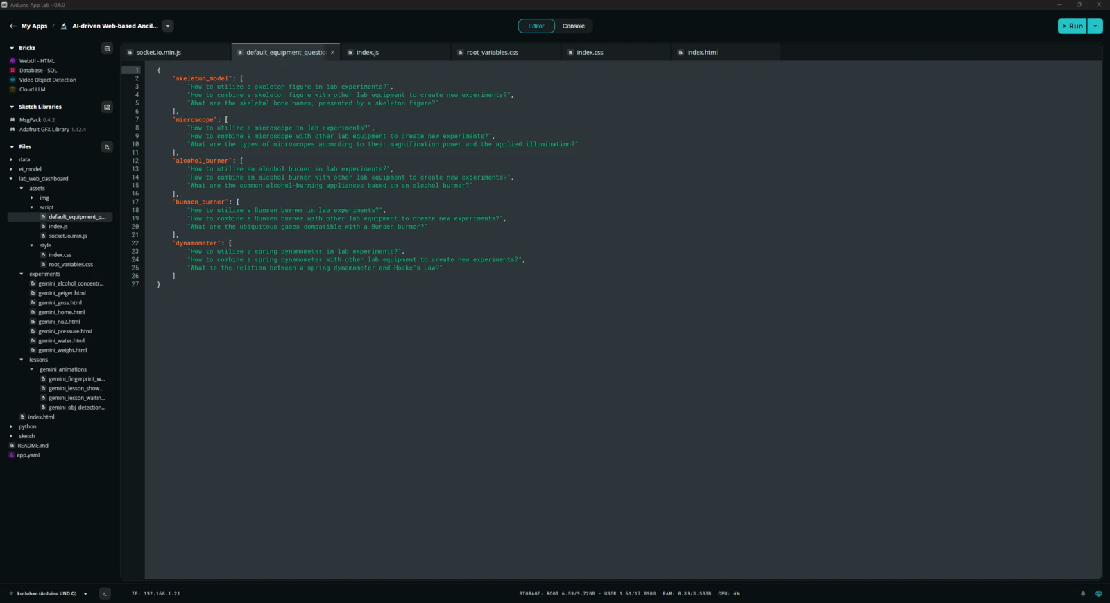
- default_equipment_questions.json
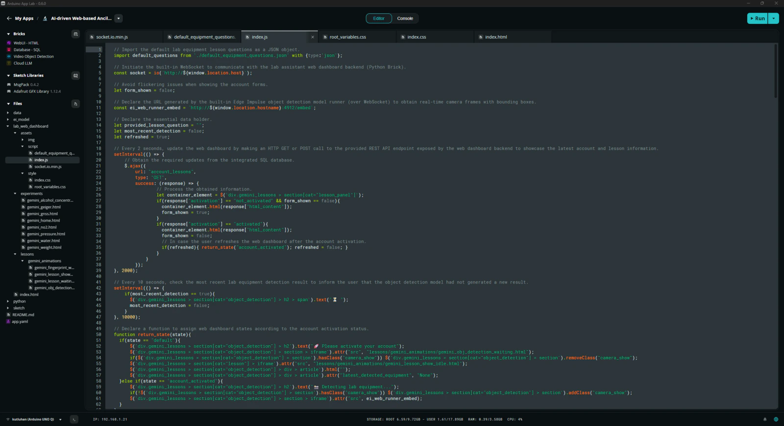
- index.js
- socket.io.min.js
-
/style
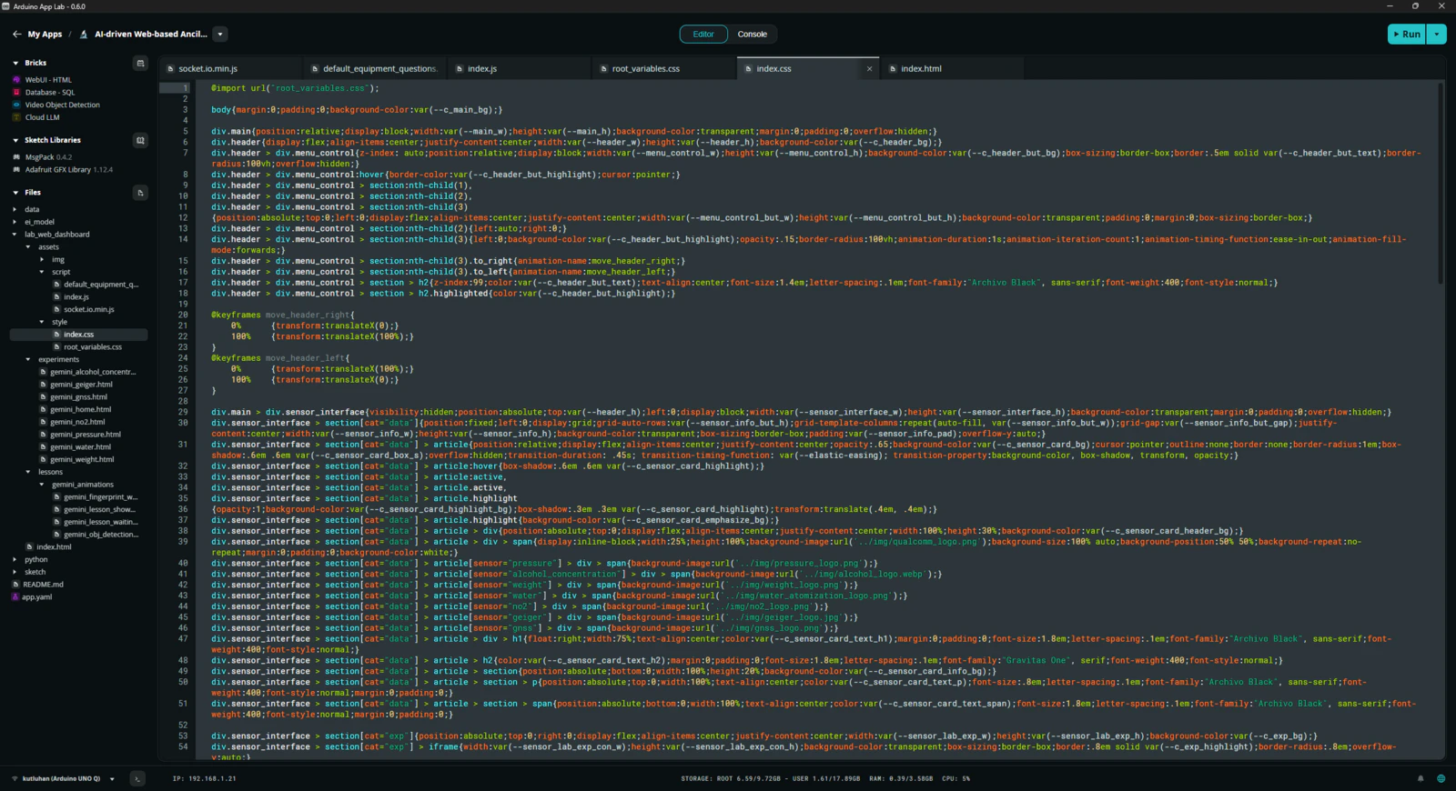
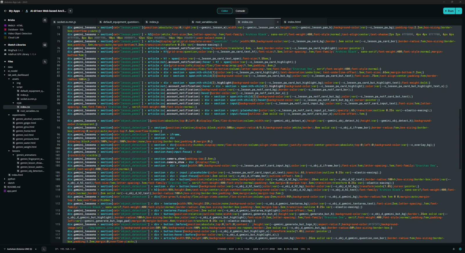
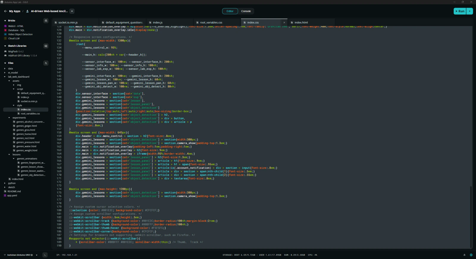
- index.css
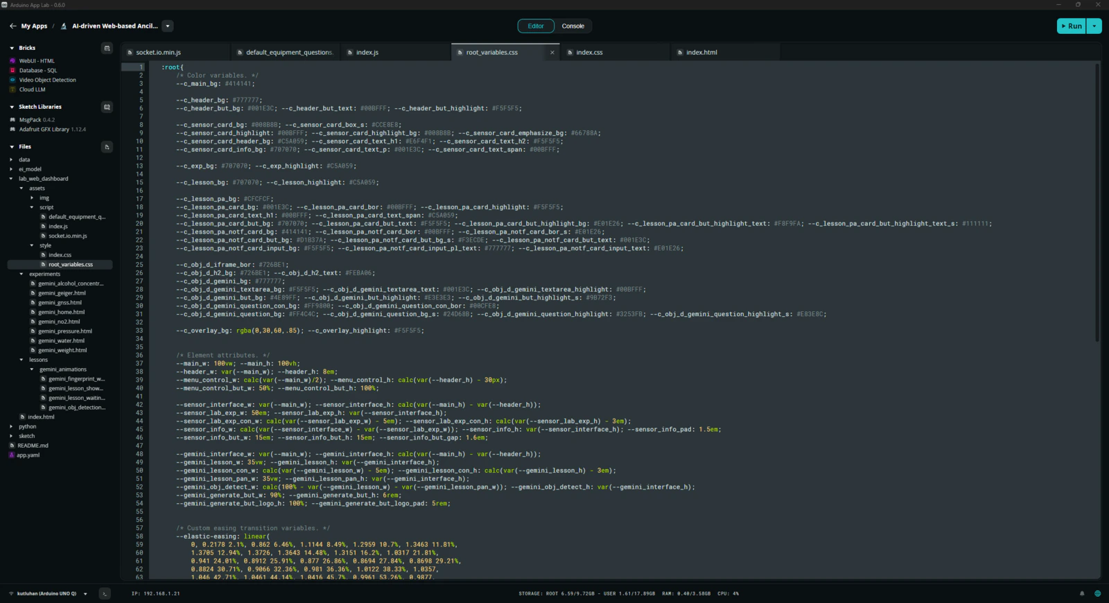
- root_variables.css
-
/experiments
- gemini_alcohol_concentration.html
- gemini_geiger.html
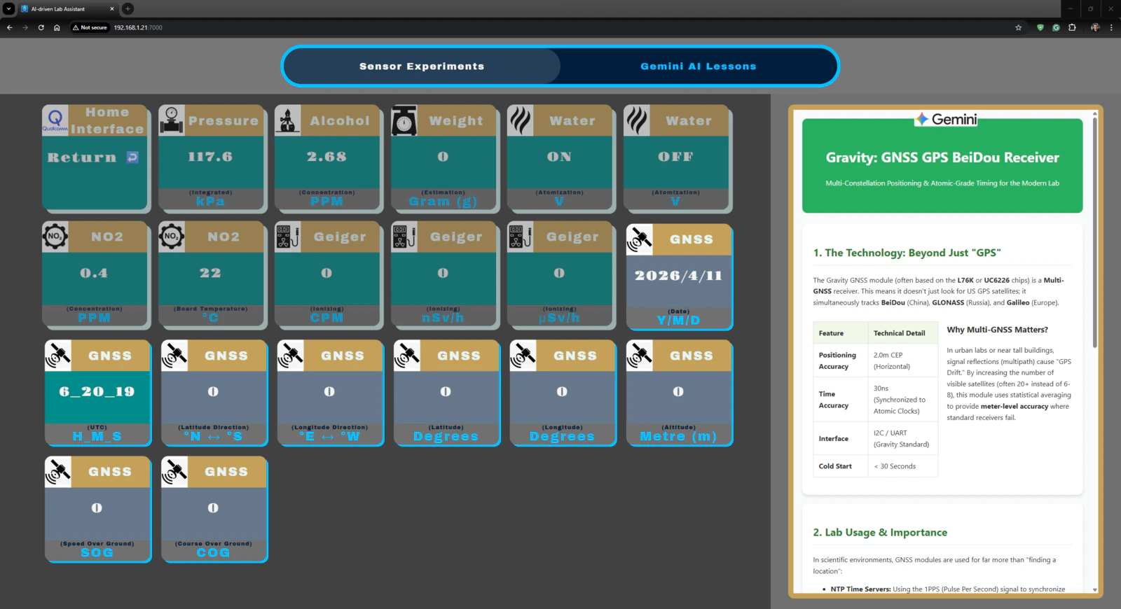
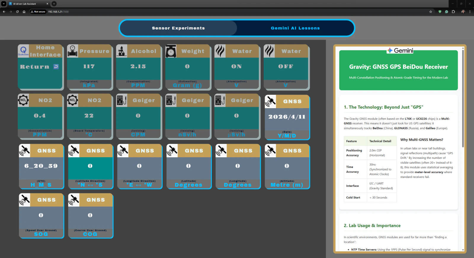
- gemini_gnss.html
- gemini_home.html
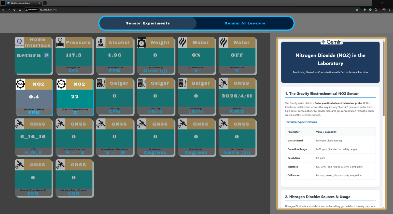
- gemini_no2.html
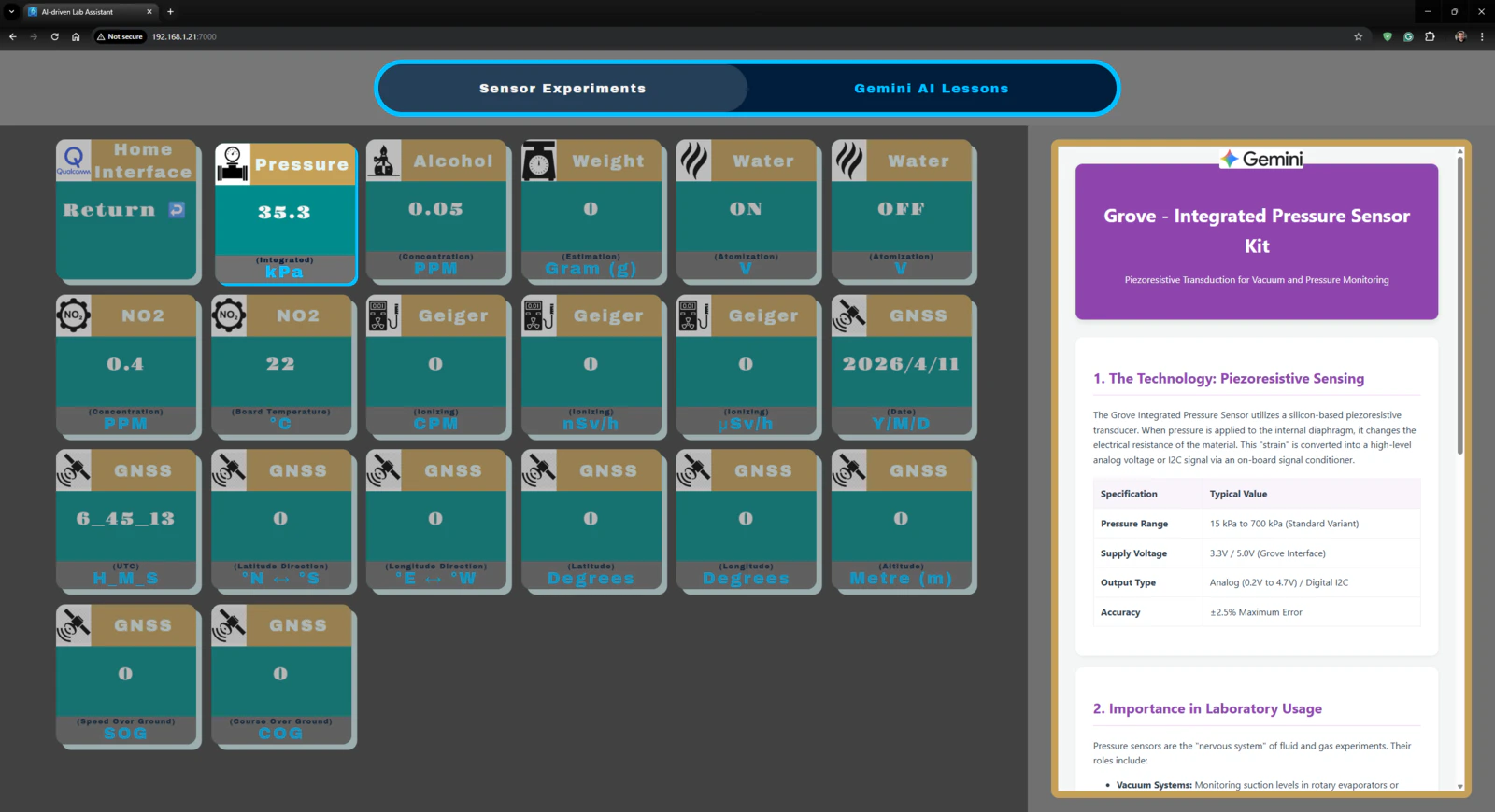
- gemini_pressure.html
- gemini_water.html
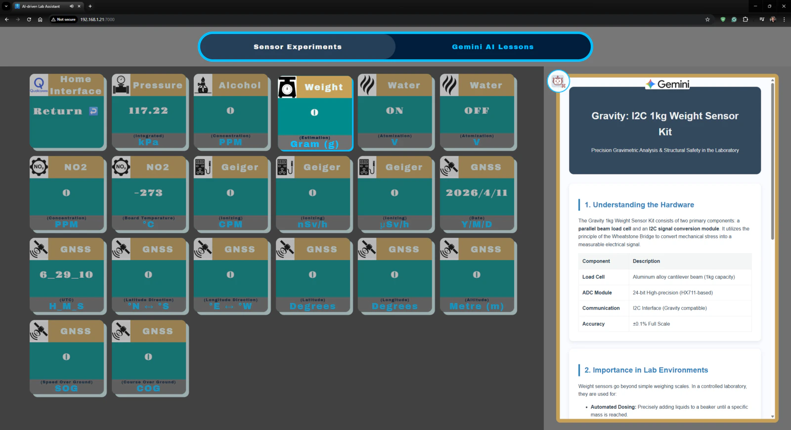
- gemini_weight.html
-
/lessons
-
/gemini_animations
- gemini_fingerprint_waiting.html
- gemini_lesson_show_idle.html
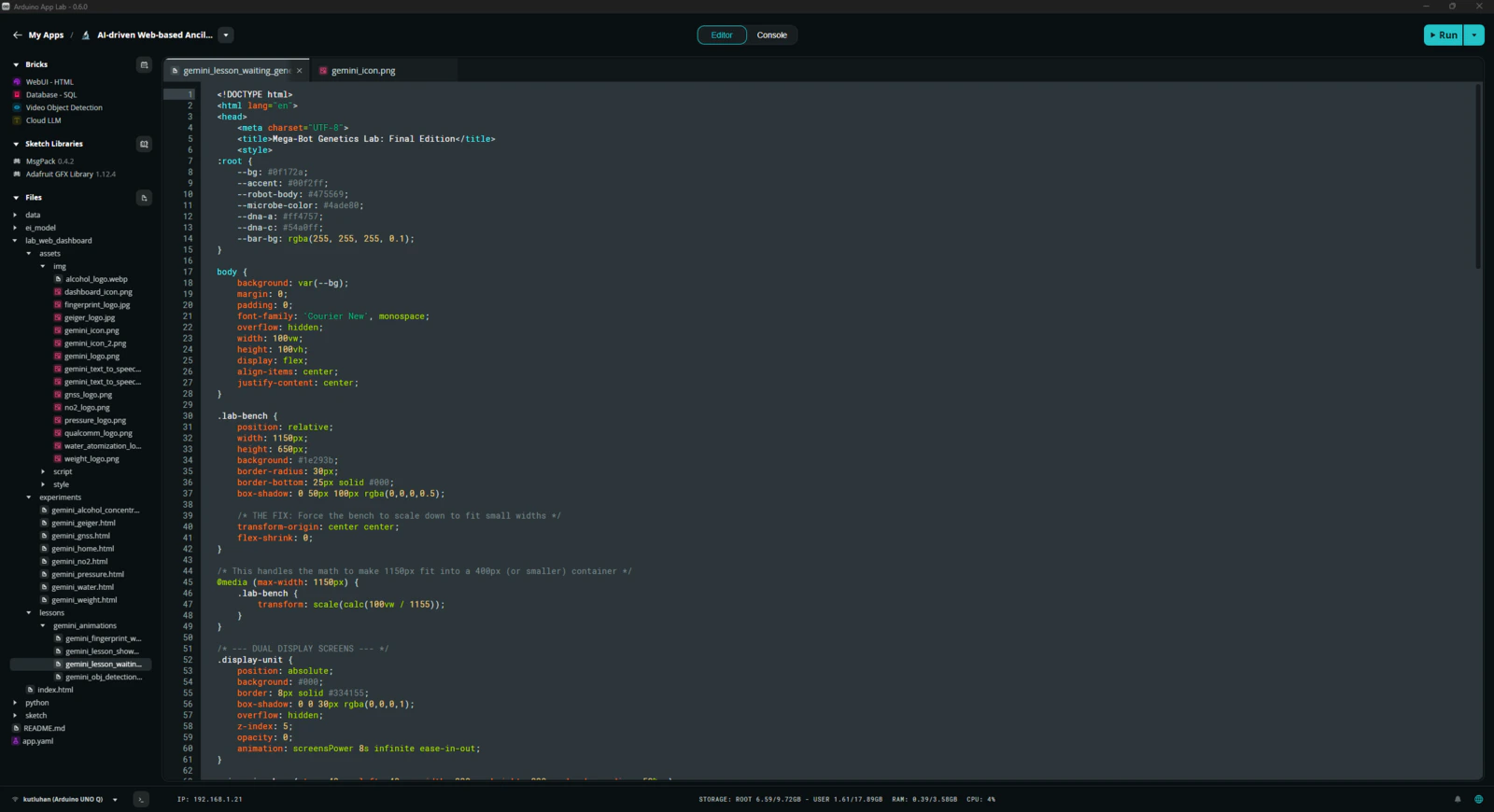
- gemini_lesson_waiting_generation.html
- gemini_obj_detection_waiting.html
-
/gemini_animations
- index.html
-
/assets
-
/python
- main.py
-
/sketch
-
/customLibs
- /DFRobot_Geiger
- /DFRobot_ID809
- /DFRobot_MultiGasSensor
- /modded_Adafruit_GC9A01A_1.1.1
- /modded_DFRobot_Alcohol_1.0.0
- /modded_DFRobot_GNSS_1.0.0
- /modded_DFRobot_HX711_I2C_1.0.0
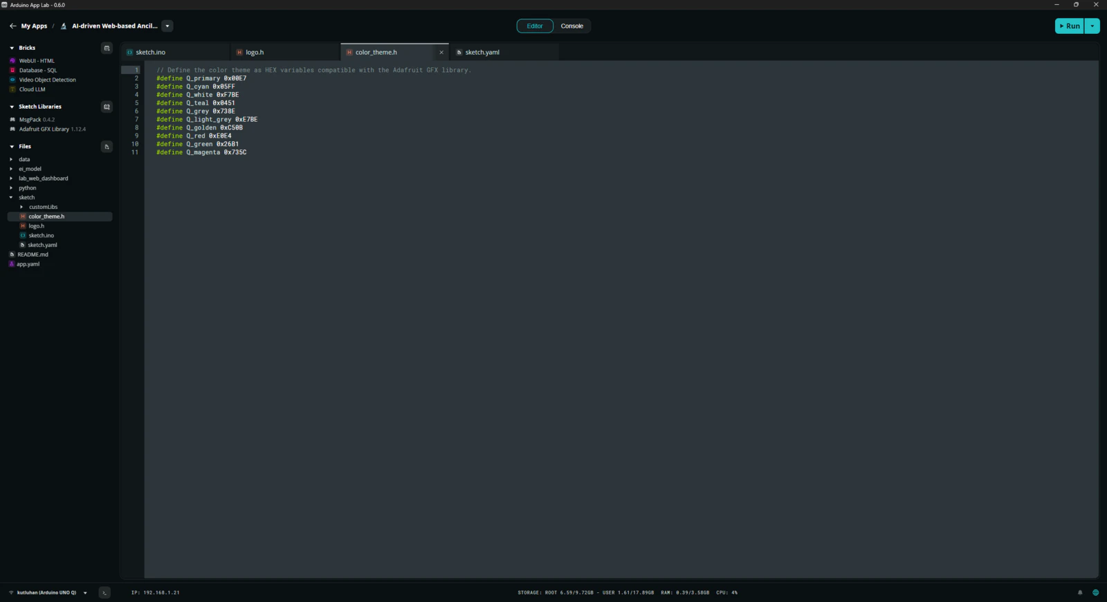
- color_theme.h
- logo.h
- sketch.ino
- sketch.yaml
-
/customLibs
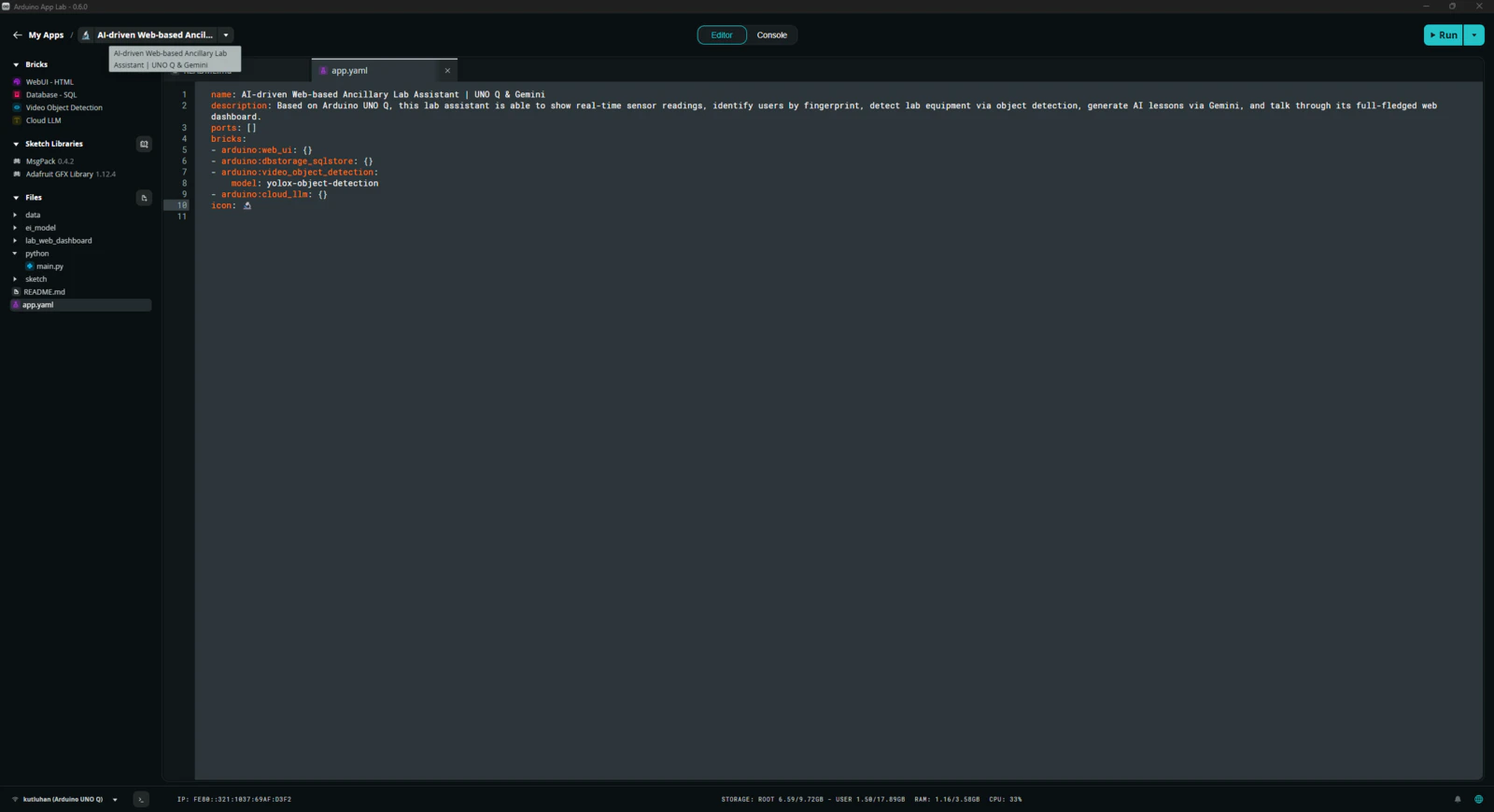
- app.yaml
- README.md
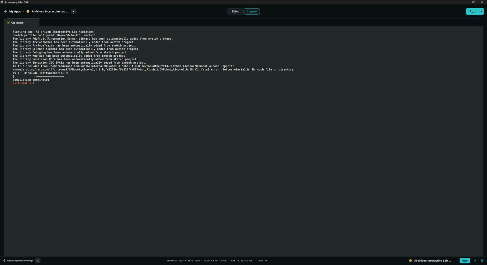
Step 7.2: Timeout issues with the latest Zephyr platform release (0.54.1)
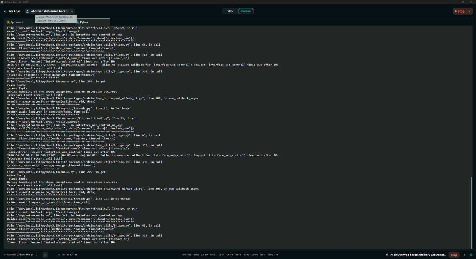
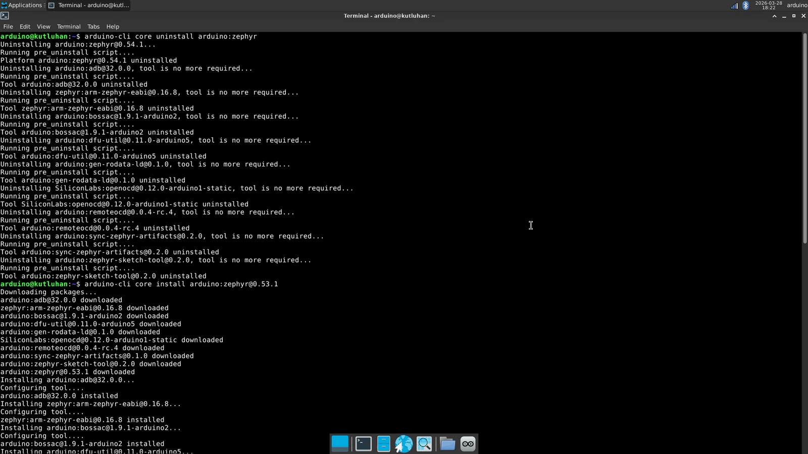
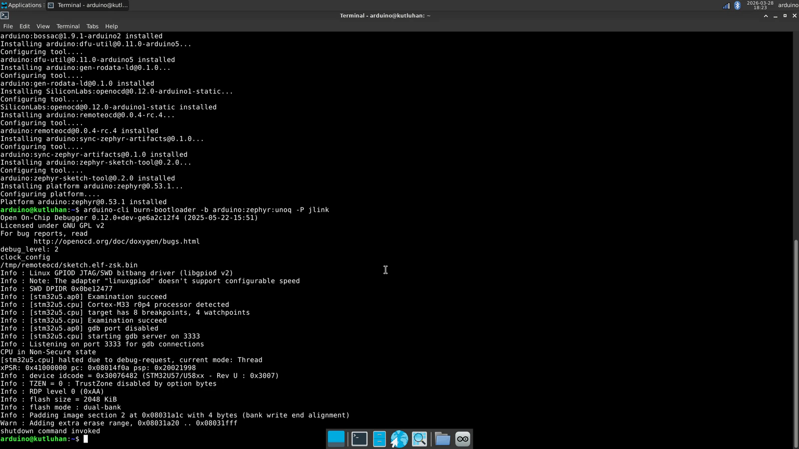
The lab assistant App Lab application was working flawlessly until the latest Zephyr Arduino core (arduino:zephyr) release (0.54.1). Once I updated Zephyr platform to this release on the Arduino App Lab, the application started to throw timeout errors incessantly and was not able to establish data transfer between the Qualcomm MPU and the STM32 MCU via the Arduino Router background Linux service. The application was not even able to run the sketch on the MCU since the Router (Bridge) service intercepted the code flow. After putting a lot of effort into running the application, I came to the conclusion that installing the Arduino_RouterBridge library as a custom sketch library outside of the bundled Zephyr platform (Arduino UNO Q Board) takes up additional dynamic memory space as global variables. Before the release of the 0.54.1 Zephyr Arduino core version, the bundled Zephyr platform included the Arduino_RouterBridge library to make it available to all App Lab applications. Nonetheless, it was removed in the 0.54.1 version and needs to be installed as a custom sketch library per application. As I was programming the application sketch, I needed to deliberately optimize functions and the number of global variables to enable the STM32 MCU to utilize the Router service without timeout errors and incompatibilities. Once I updated the Arduino App Lab to the 0.54.1 version, I installed the Arduino_RouterBridge library as requested and started to get continuous timeout errors regarding the Router service despite all my efforts to fix them.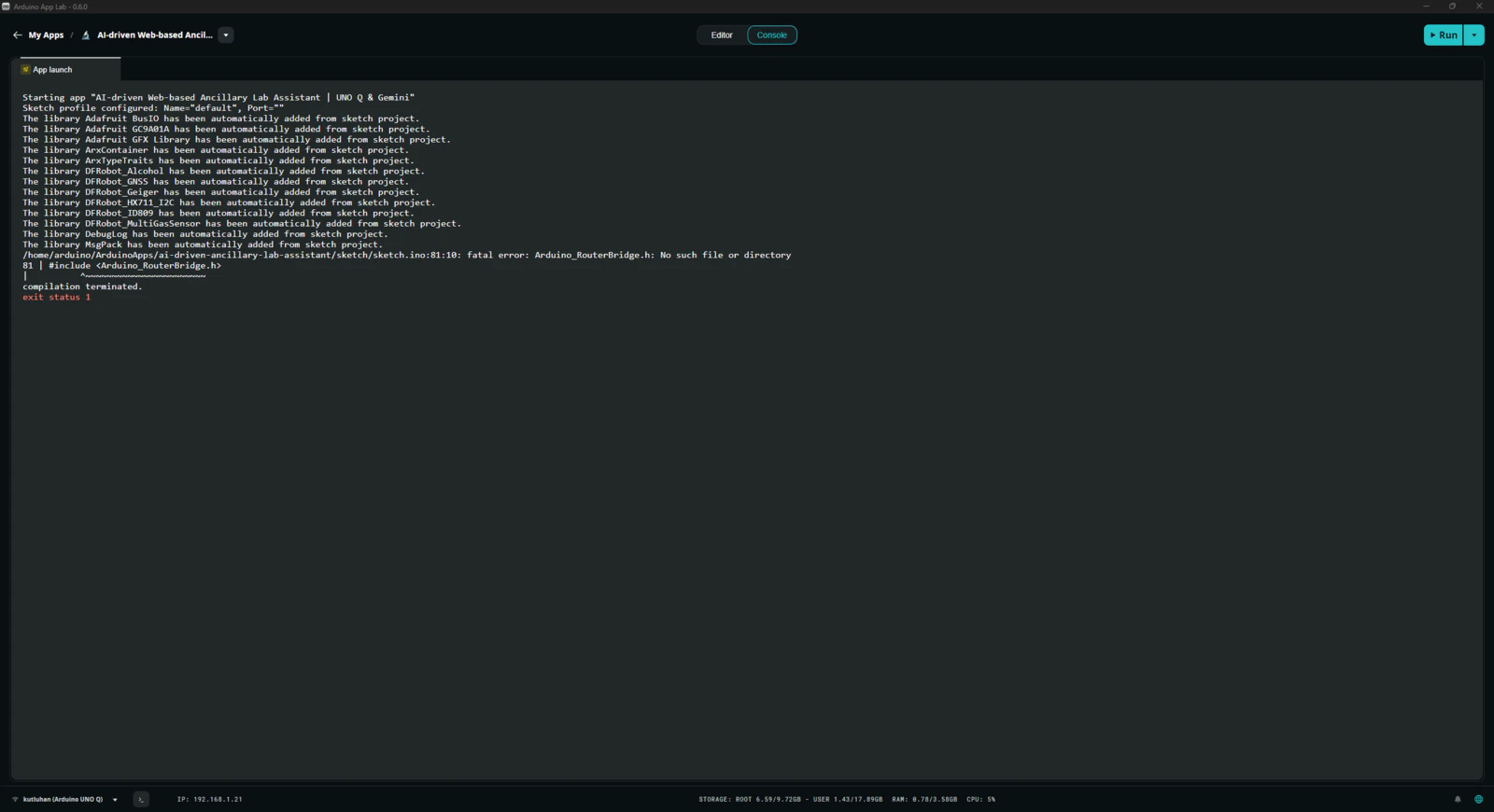
Step 7.3: Continuing issues with the most recent Zephyr platform (0.55.0)
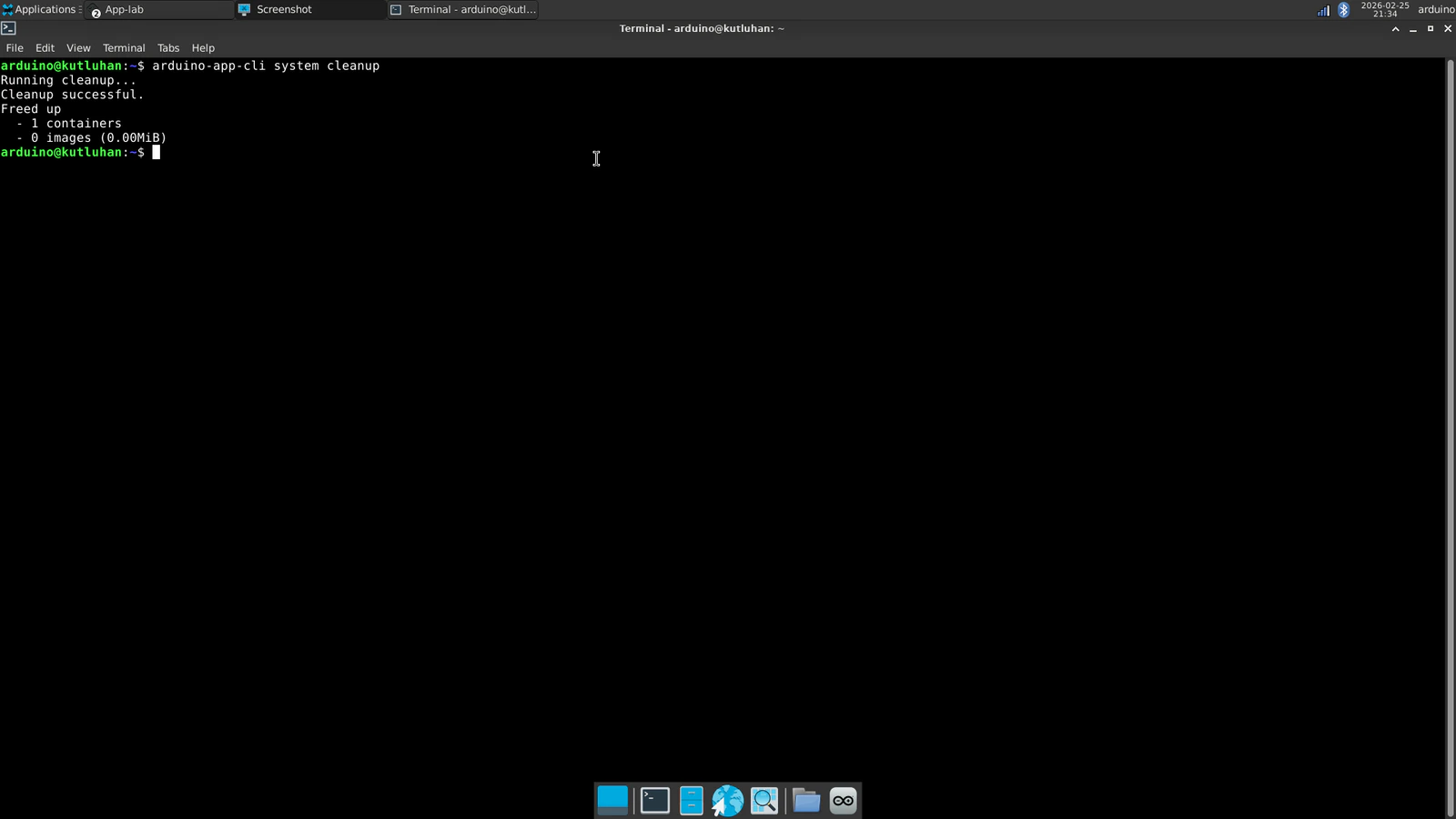
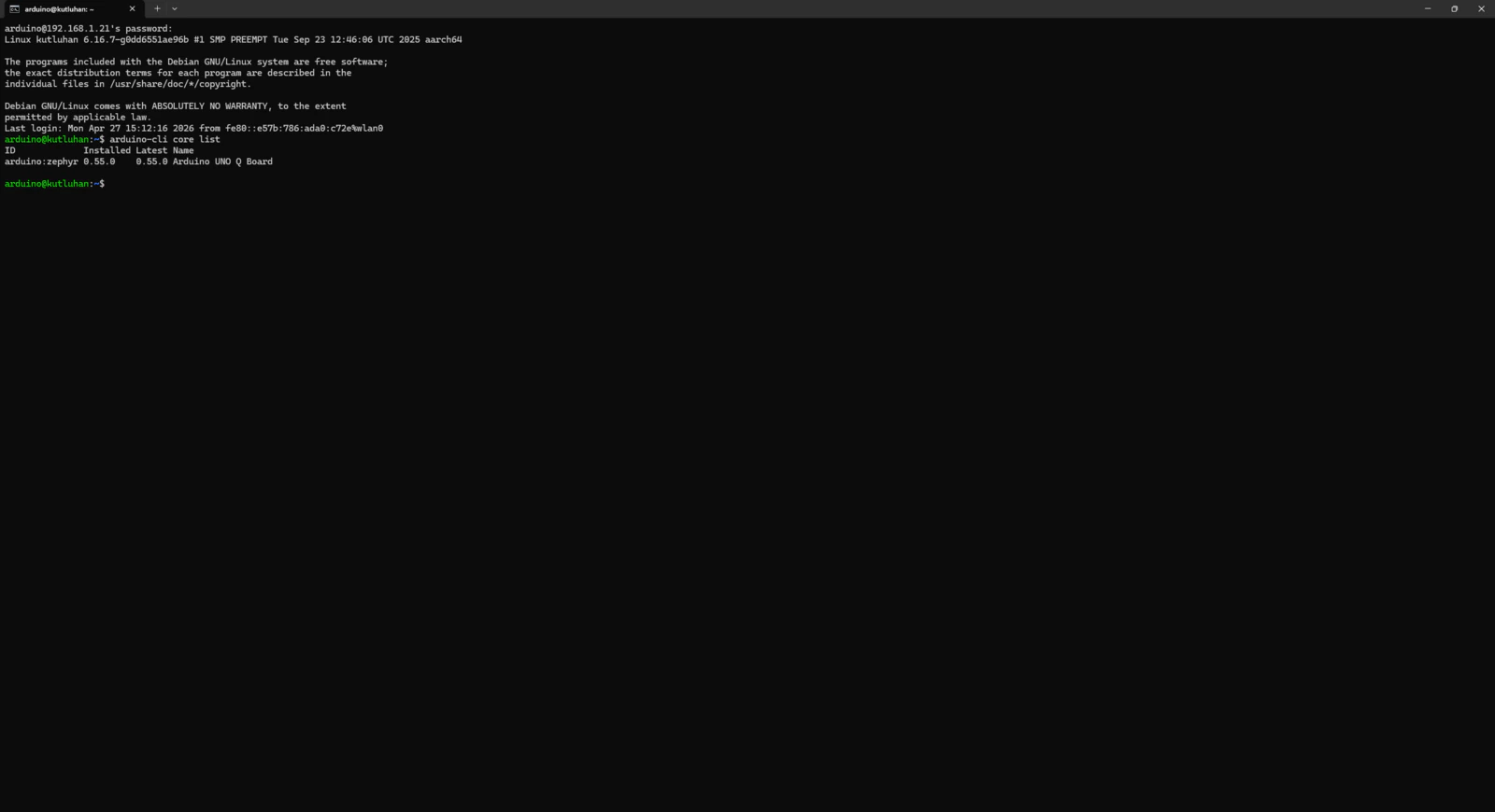
After I completed this project tutorial and was nearing publication, Arduino released new updates for Arduino App Lab and the Zephyr Arduino core (arduino:zephyr). Thus, I decided to test these new versions to see whether the timeout issues remain. #️⃣ Once you open the Arduino App Lab, it should ask permission to install the latest versions automatically.- arduino:zephyr Version 0.55.0
- arduino-app-cli Version 0.9.0
- arduino-app-lab Version 0.7.0
- arduino-router Version 0.8.1


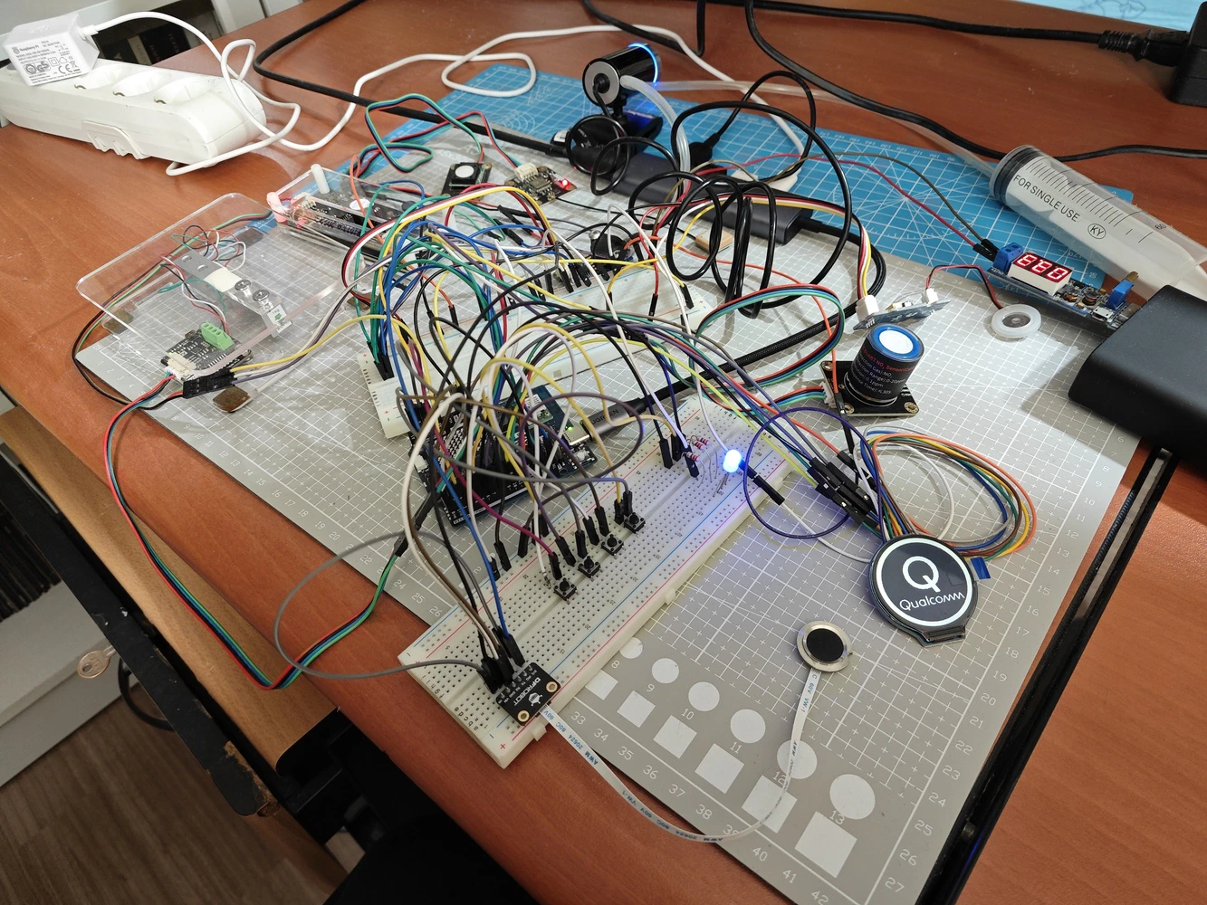
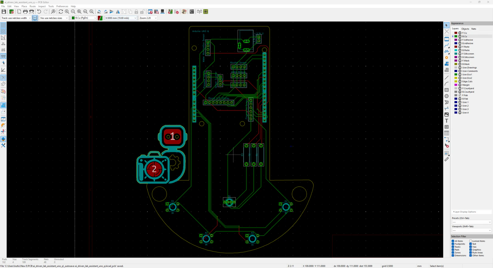
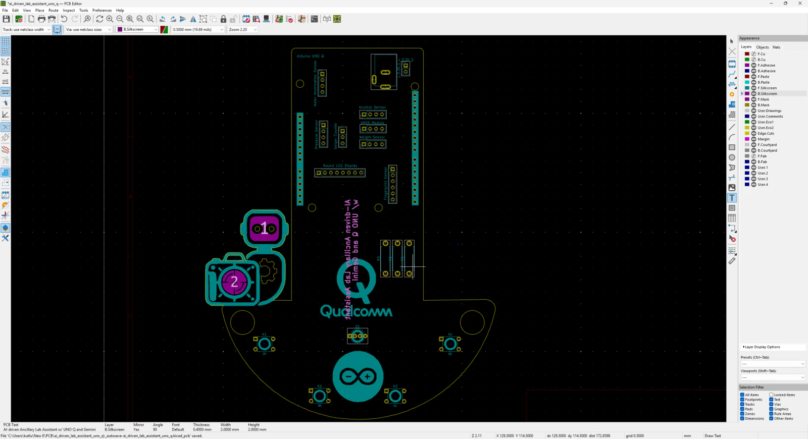
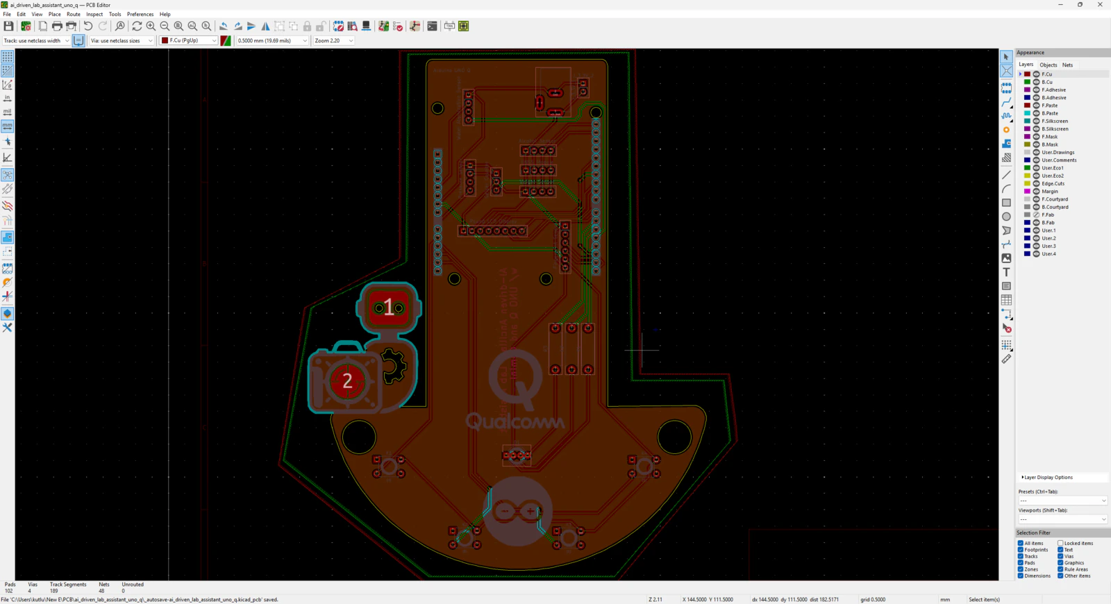
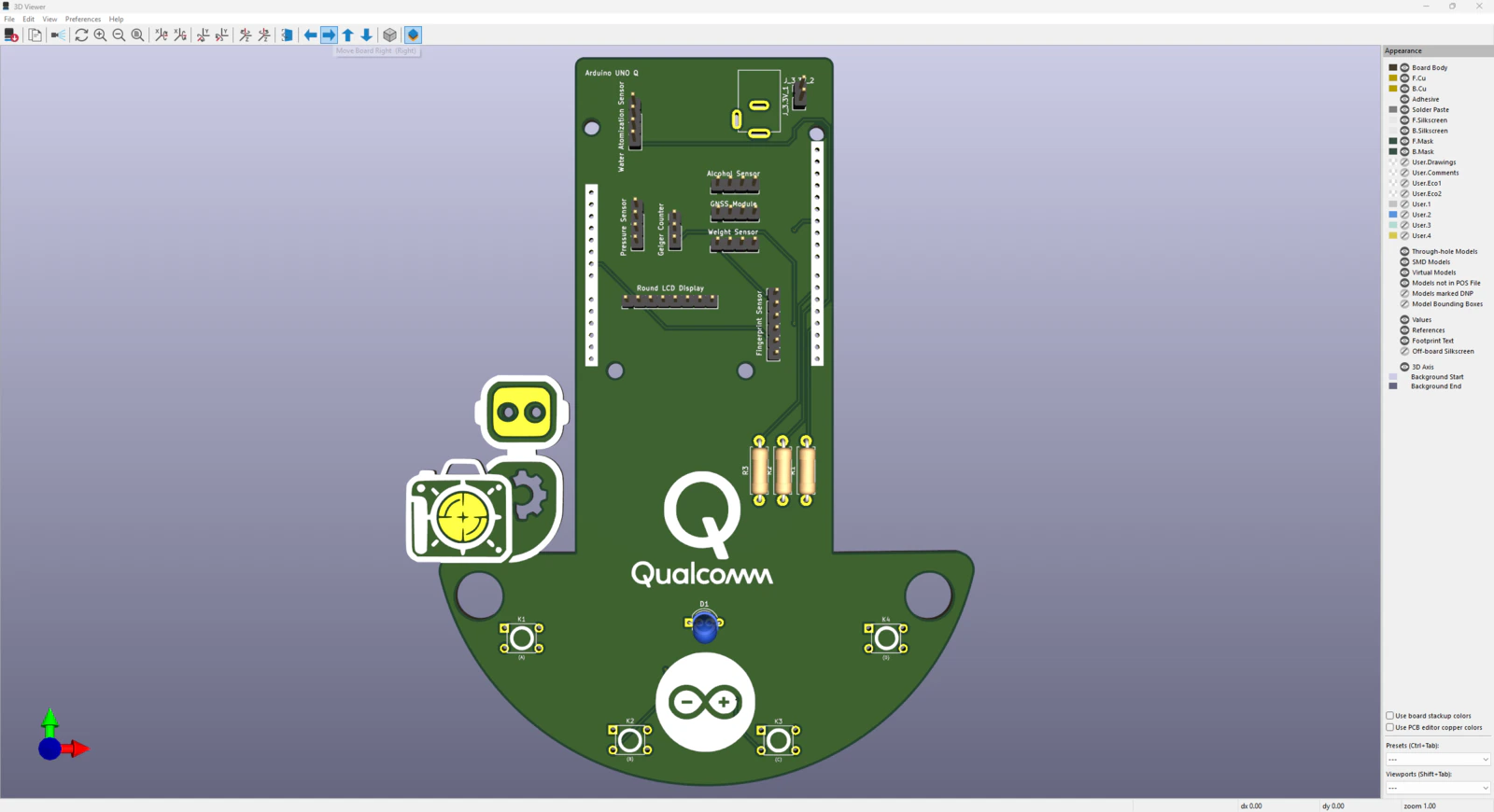
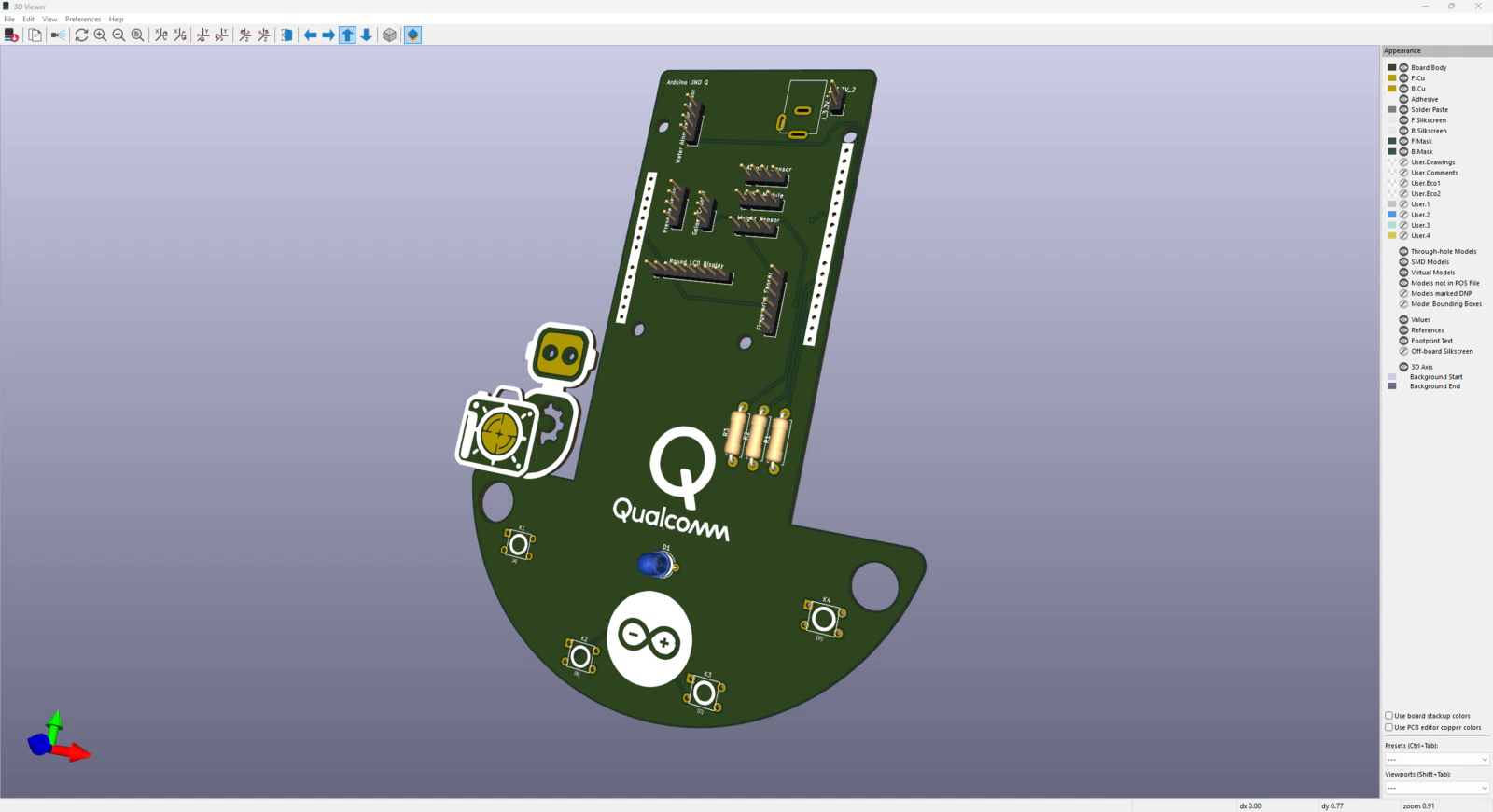
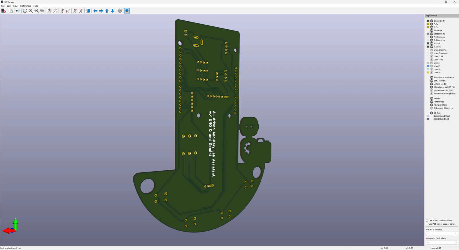
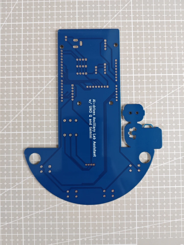
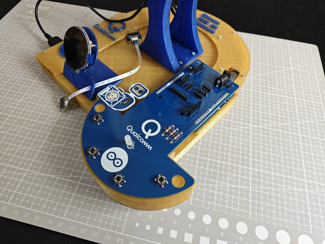
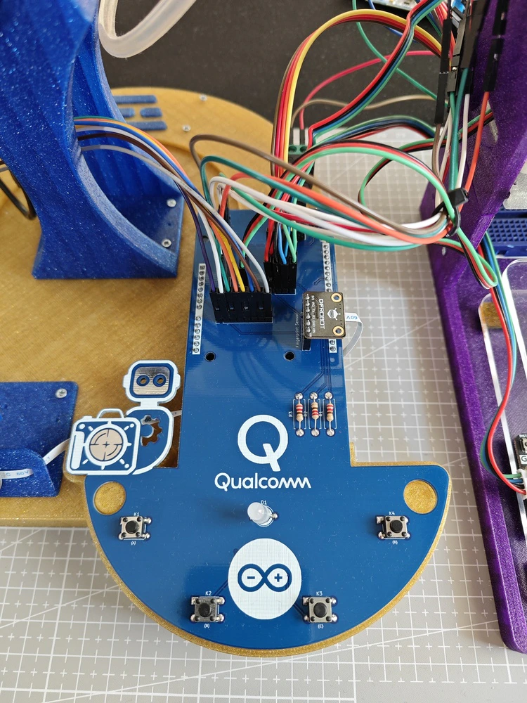
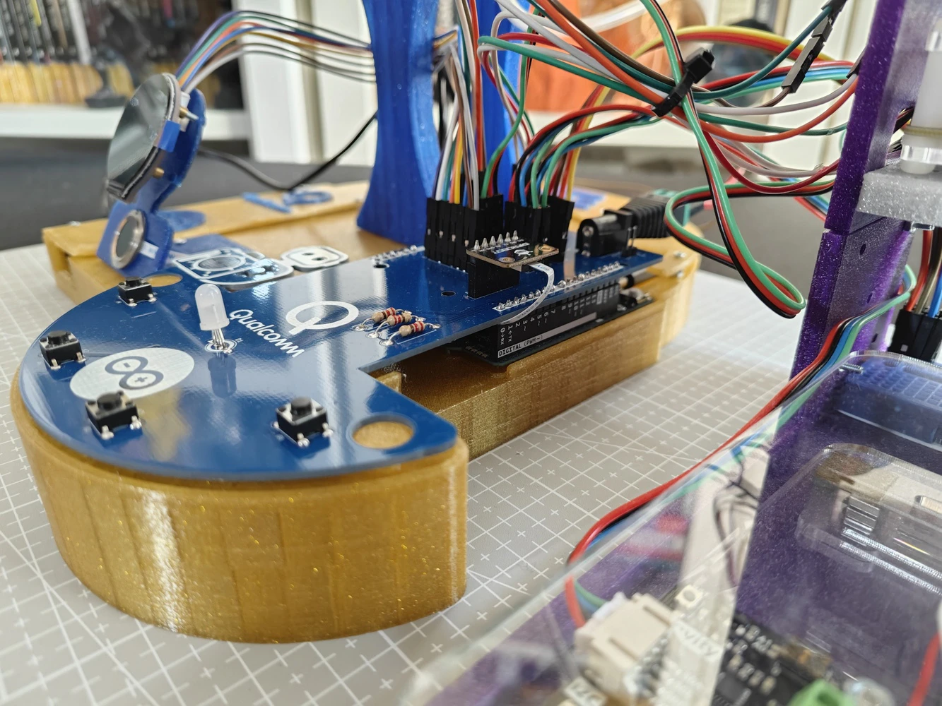
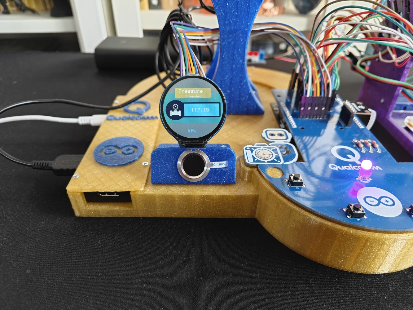
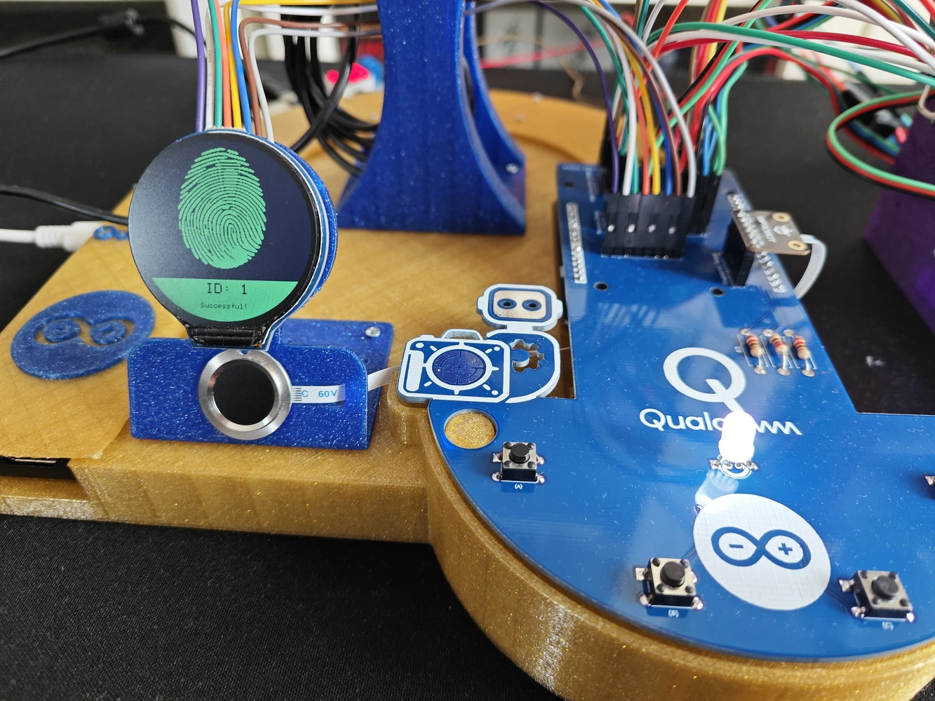
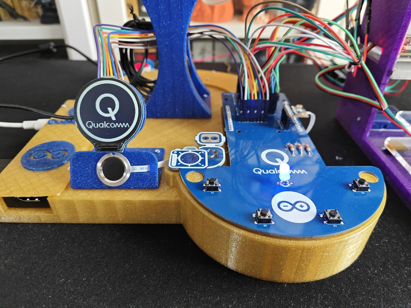
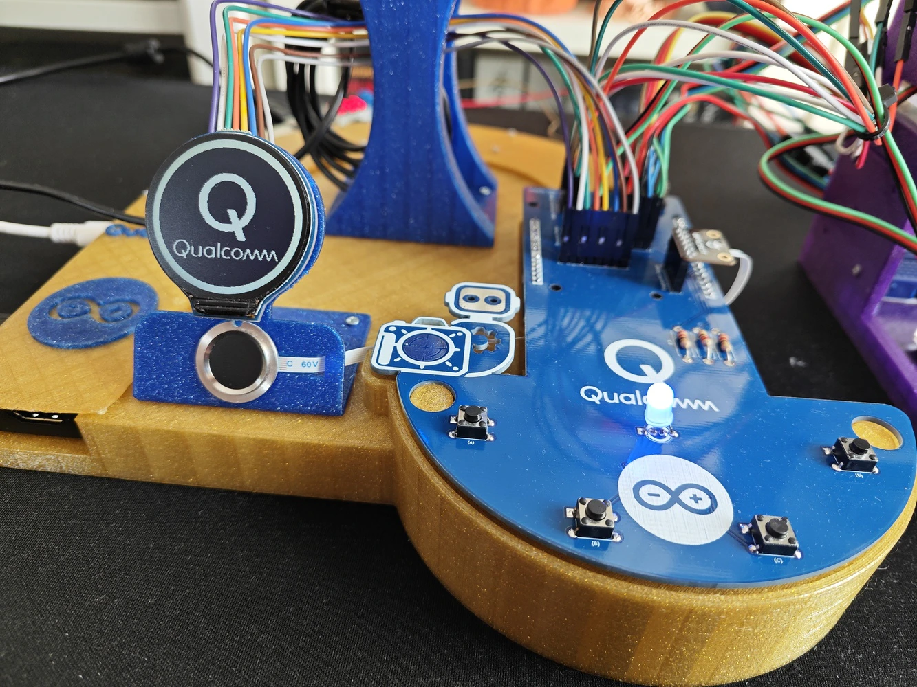
Step 8: Designing the lab assistant analog interface PCB as an Arduino UNO Q shield (hat)
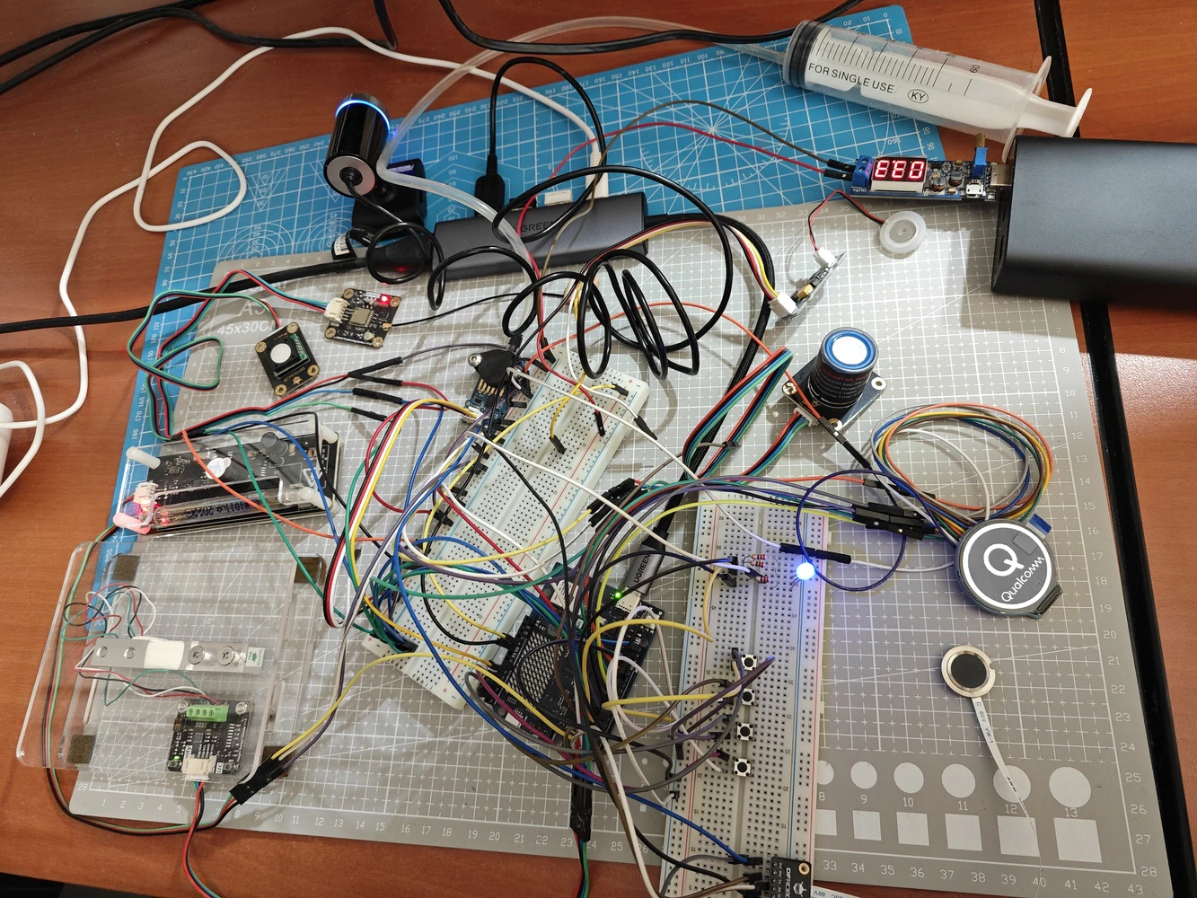
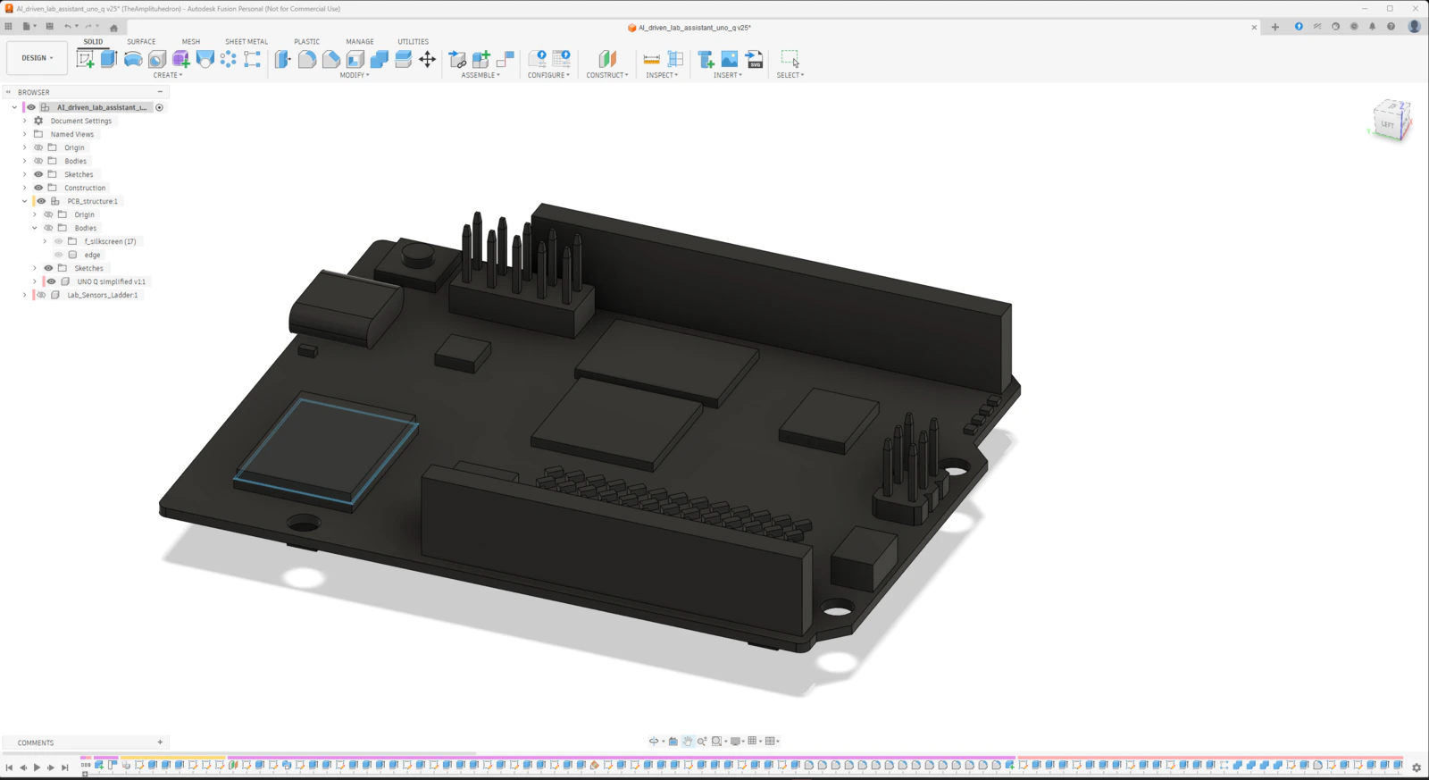
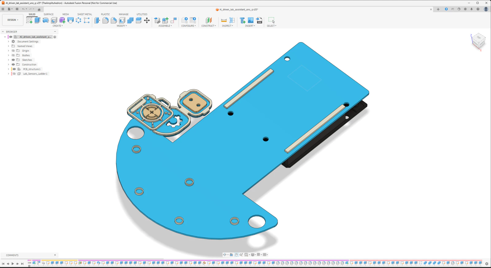
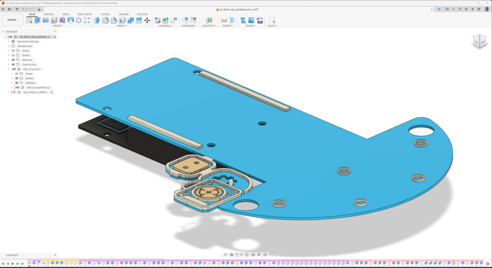
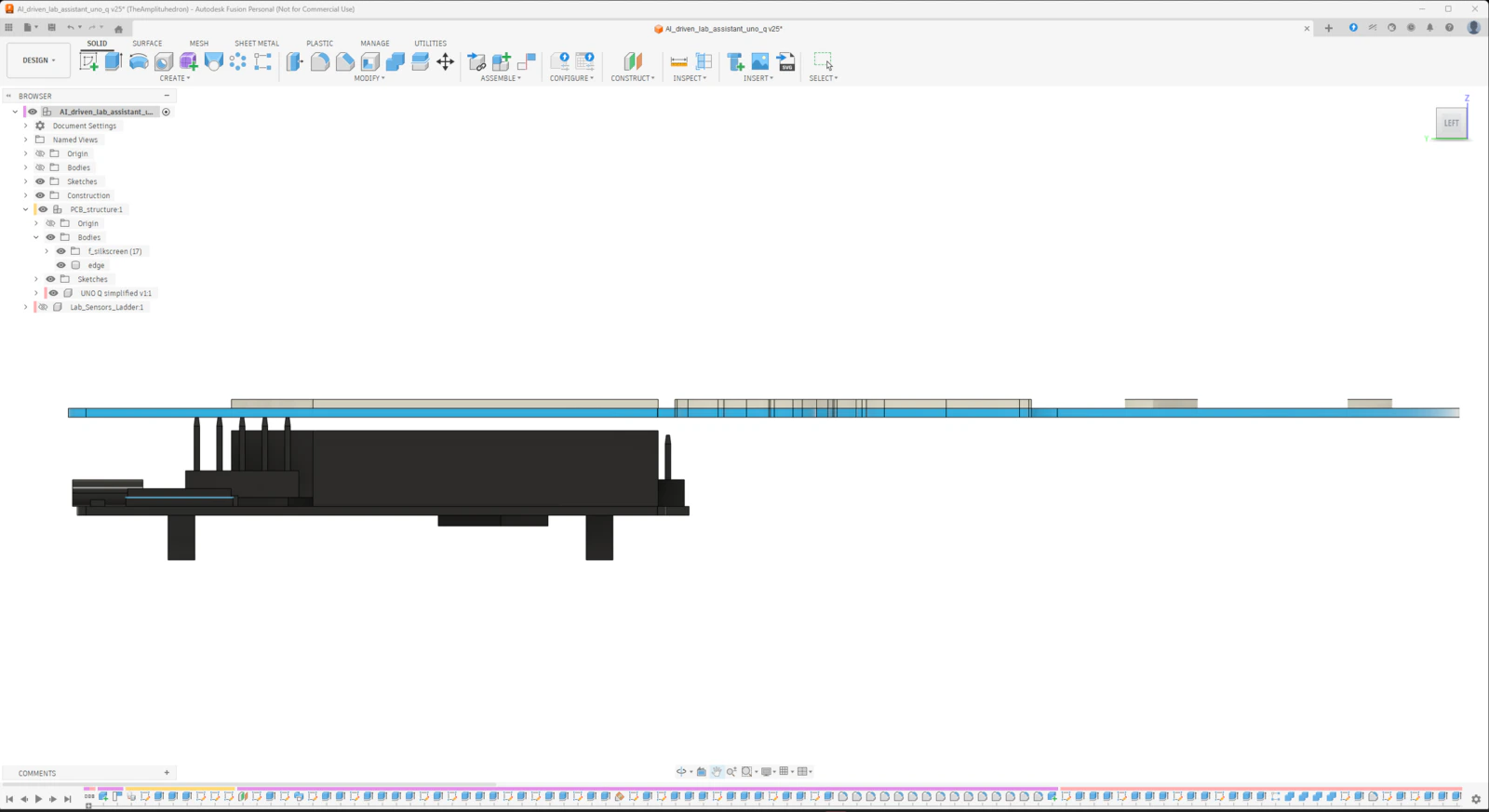
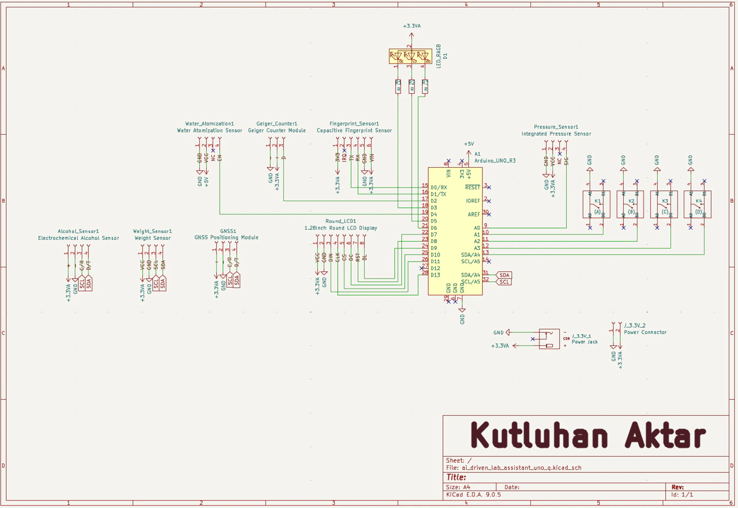
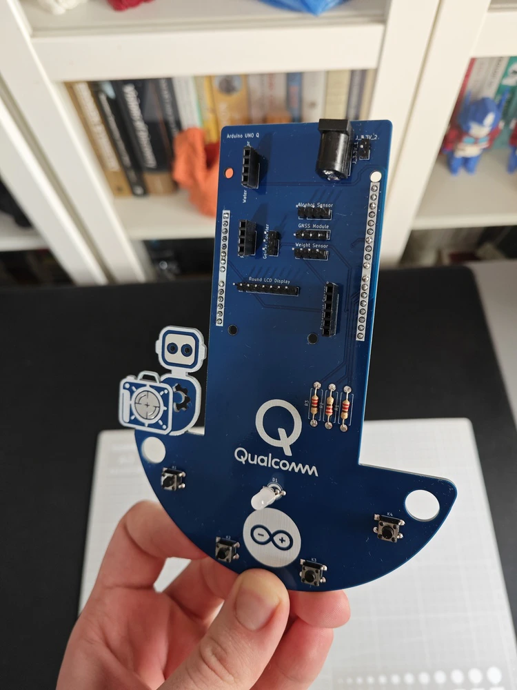
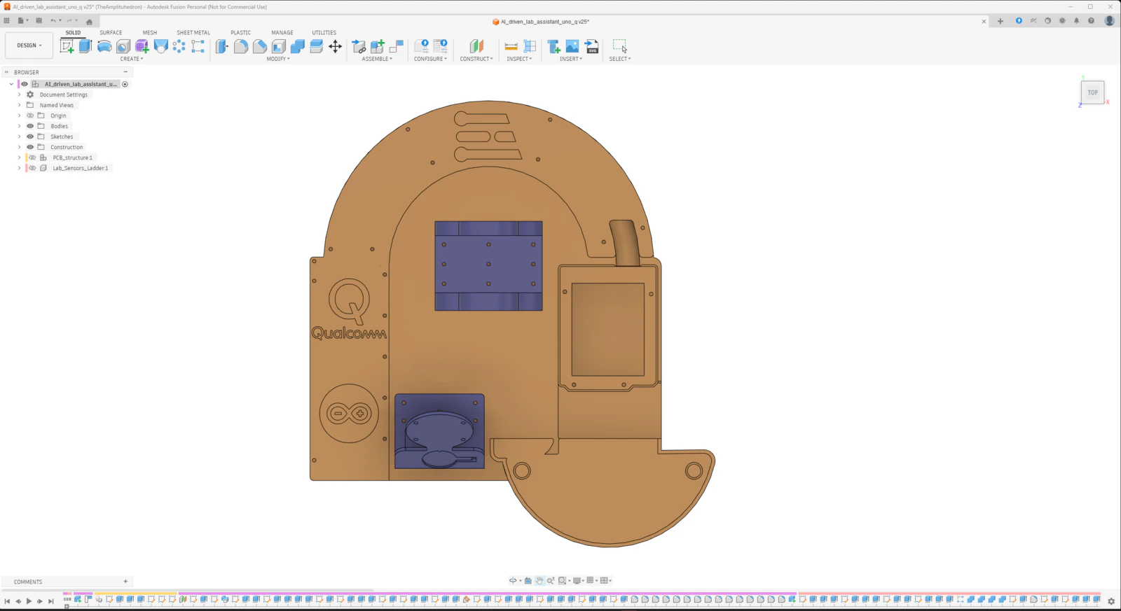
After developing the lab assistant App Lab application and ensuring all electronic components work as expected, I started to design the lab assistant analog interface PCB layout. According to my refined development process for modeling distinct PCBs and compatible 3D parts, I prefer designing PCB outlines and layouts (silkscreen, copper layers, etc.) directly on Autodesk Fusion 360 and culminating my proof-of-concept device structures around the PCB layouts. Having a PCB digital twin allows me to simulate a complex 3D mechanical structure to make its components compatible with the PCB’s part placement and outline before sending the PCB design for manufacturing. In this case, creating the PCB layout on Fusion 360 was greatly beneficial since I decided to design the analog interface PCB as a unique Arduino UNO Q shield (hat). As I was working on the analog interface PCB layout, I leveraged the open-source CAD file of Arduino UNO Q to obtain accurate measurements:- ✒️ Arduino UNO Q (Step) | Inspect
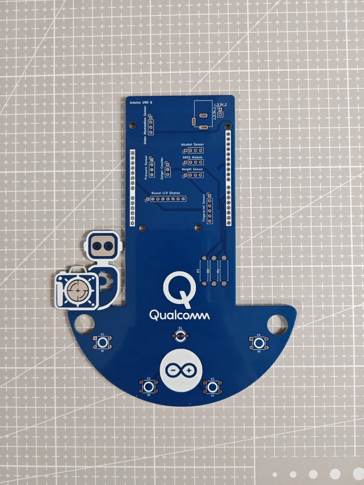
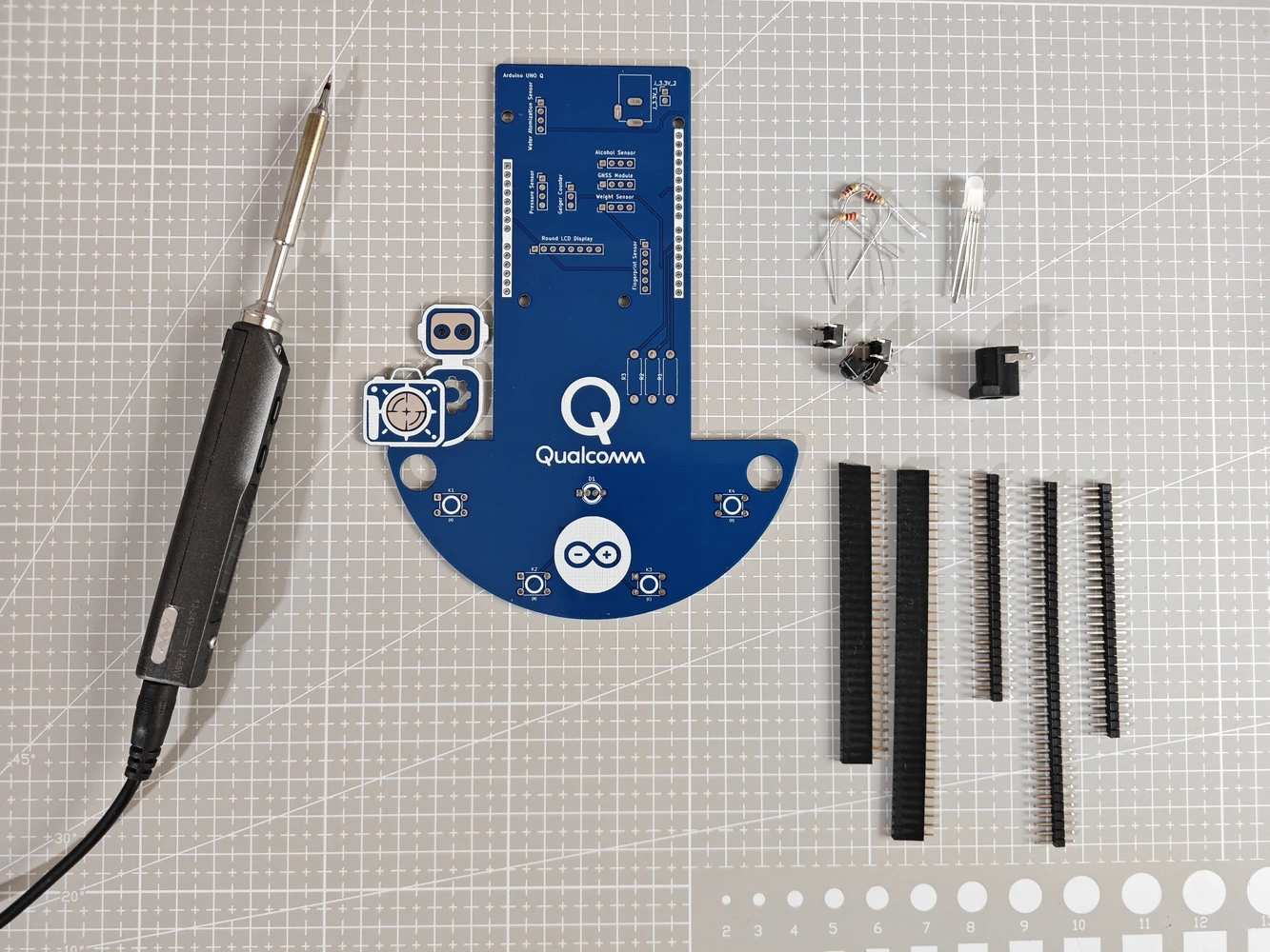
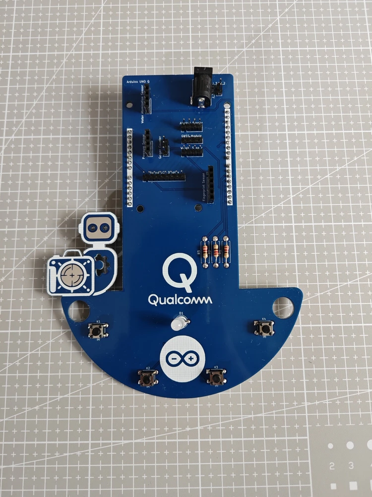
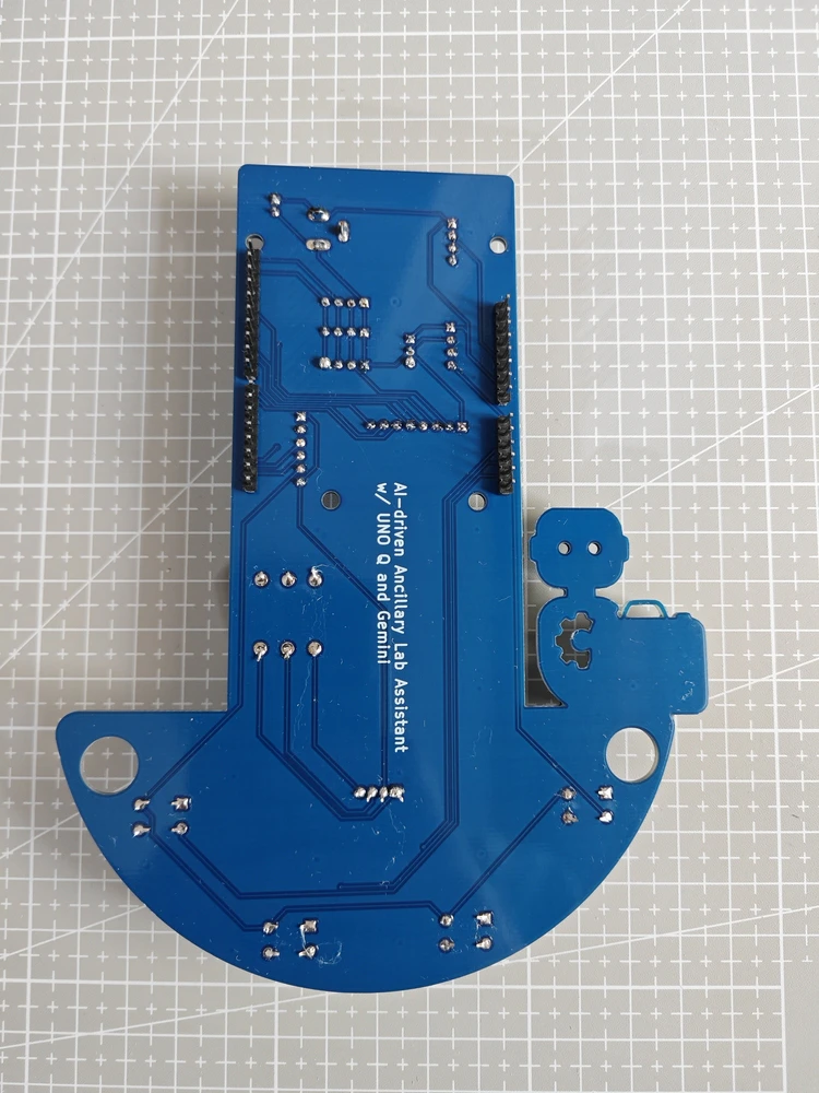
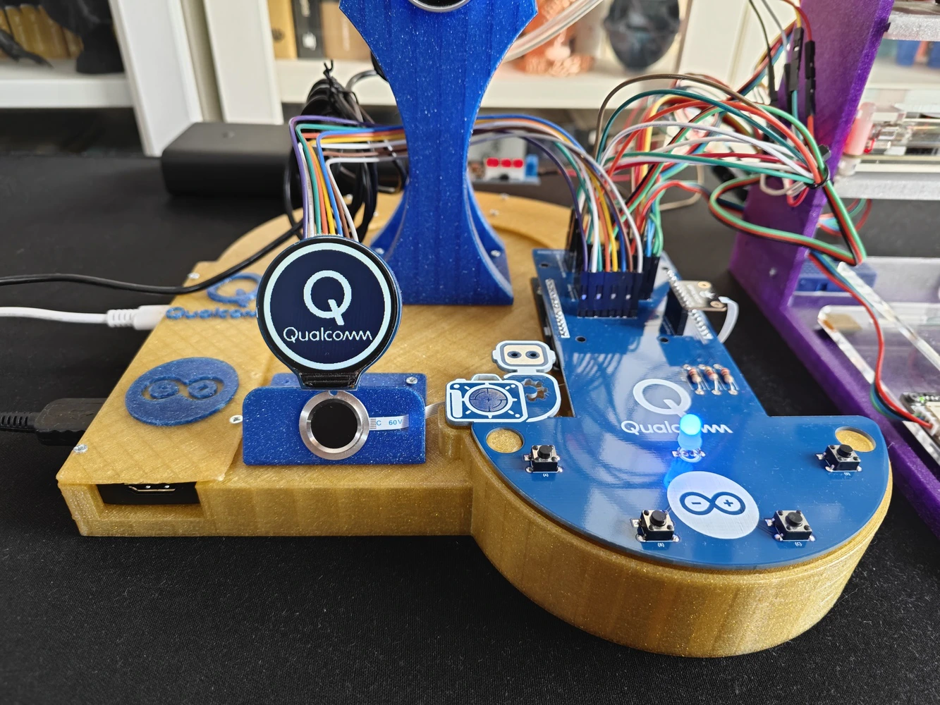
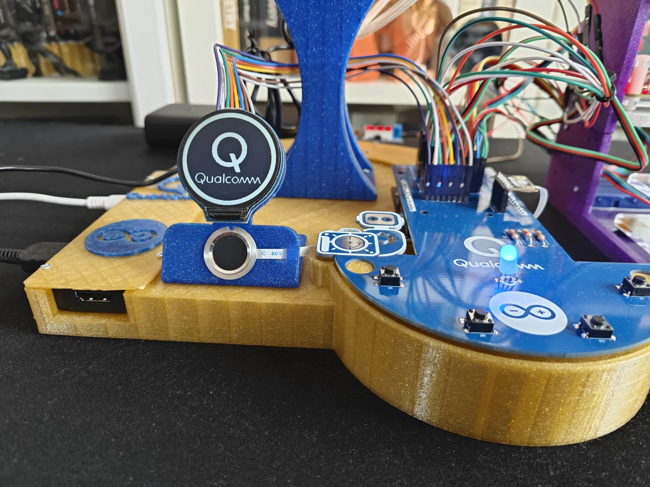
Step 8.1: Soldering and assembling the lab assistant analog interface PCB
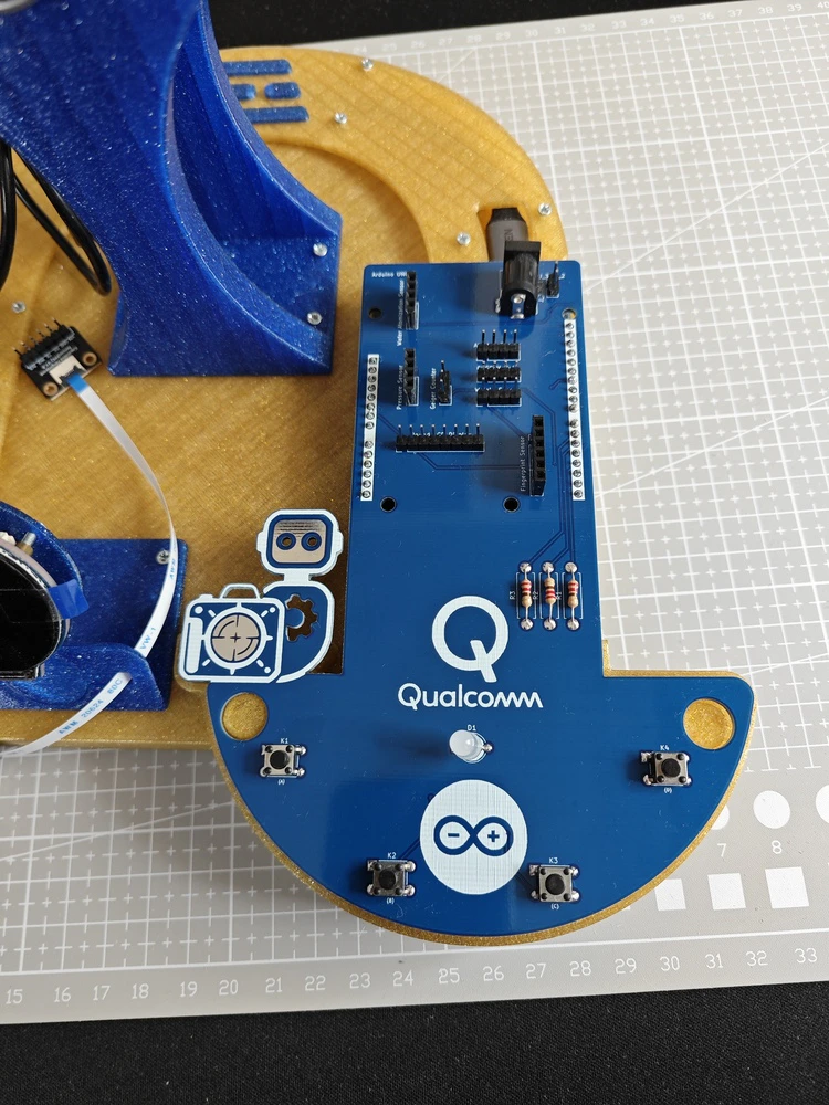
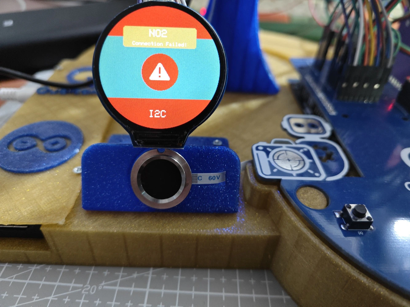
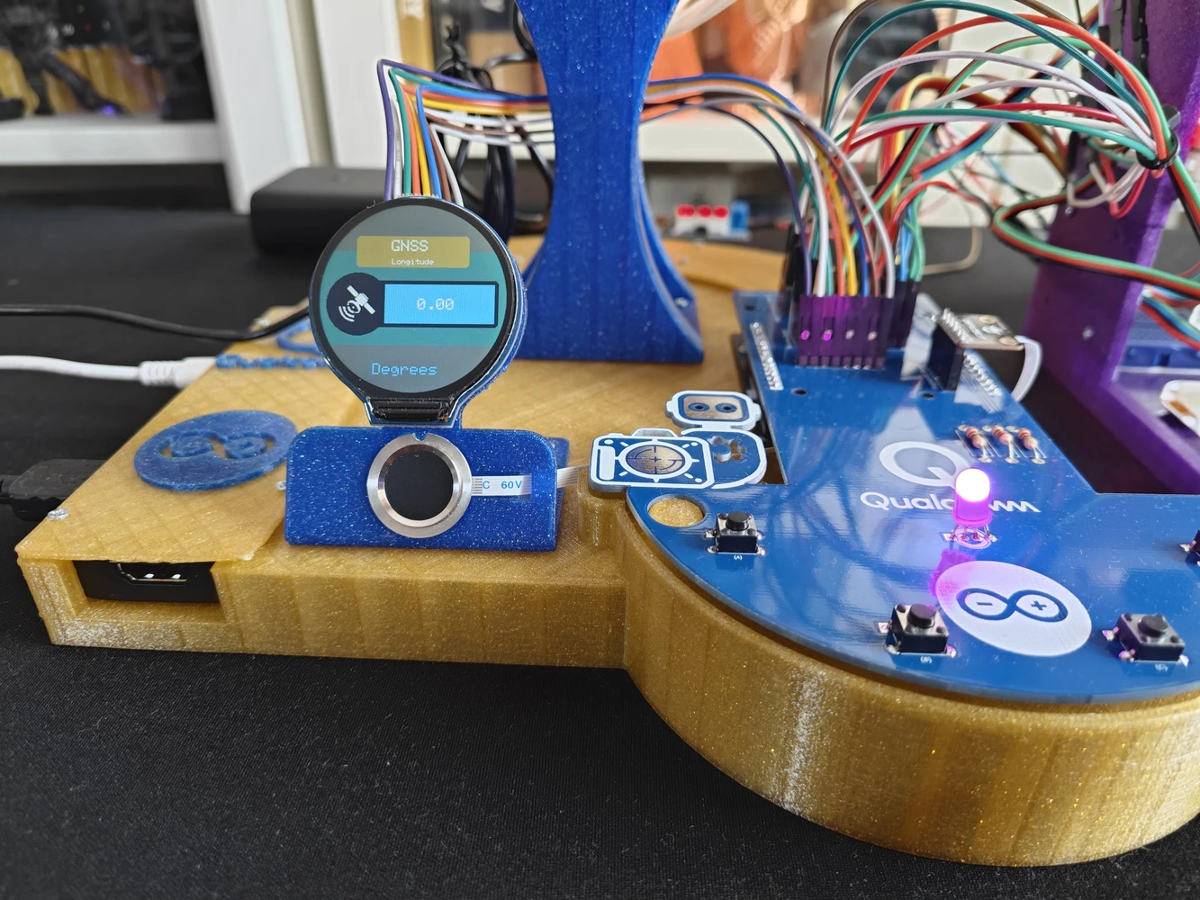
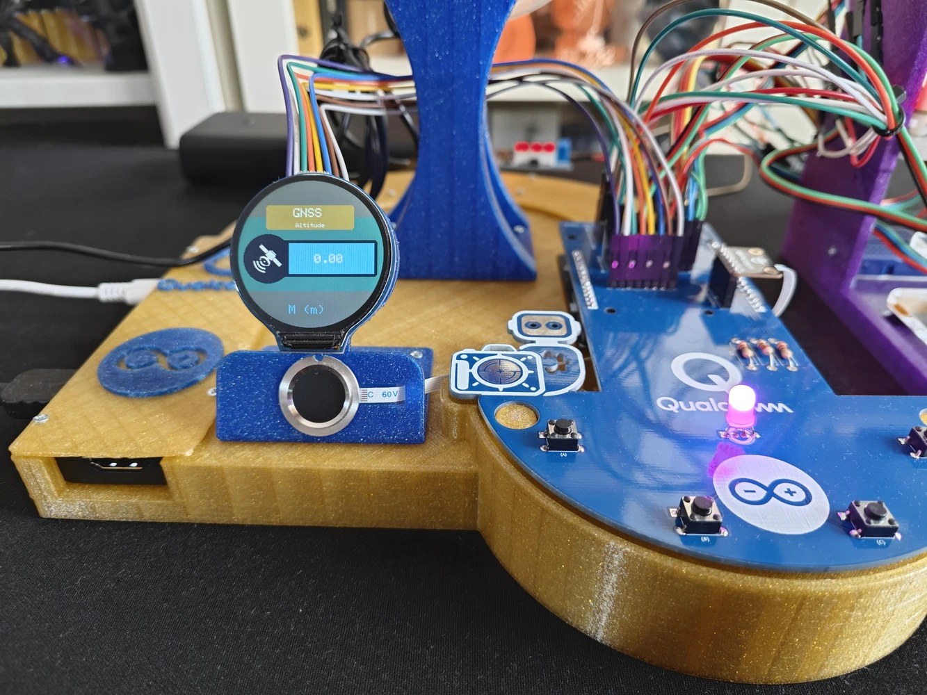
For further inspection, I provided the Gerber and fabrication files on the project GitHub repository. ❗ Important: As I was designing the circuitry, I forgot to add a dedicated header for the electrochemical NO2 sensor. Since I tested lots of lab sensors employing the I2C communication protocol while developing the lab assistant, I missed that the NO2 sensor did not have a dedicated header in the final layout. Thus, I utilized a mini breadboard to split the I2C line and connect the NO2 sensor. As long as you have an I2C-compatible sensor, you can connect it directly via the three dedicated I2C ports on the PCB. If you want to connect more than three I2C sensors, you can split the I2C line as I did. #️⃣ After receiving my PCBs, I soldered electronic components and pin headers via my TS100 soldering iron to place all parts according to my PCB layout. 📌 Component assignments on the lab assistant analog interface PCB: A1 (Headers for Arduino UNO Q) Fingerprint_Sensor1 (Headers for Capacitive Fingerprint Sensor) Geiger_Counter1 (Headers for Geiger Counter Module) Alcohol_Sensor1 (Headers for Electrochemical Alcohol Sensor) Water_Atomization1 (Headers for Water Atomization Sensor) Weight_Sensor1 (Headers for Weight Sensor) Pressure_Sensor1 (Headers for Integrated Pressure Sensor) GNSS1 (Headers for GNSS Positioning Module) Round_LCD1 (Headers for GC9A01 Round LCD Display) K1, K2, K3, K4 (6x6 Pushbutton) D1 (5mm Common Anode RGB LED) R1, R2, R3 (220Ω Resistor) J_3.3V_1 (DC Barrel Female Power Jack) J_3.3V_2 (Headers for Power Supply)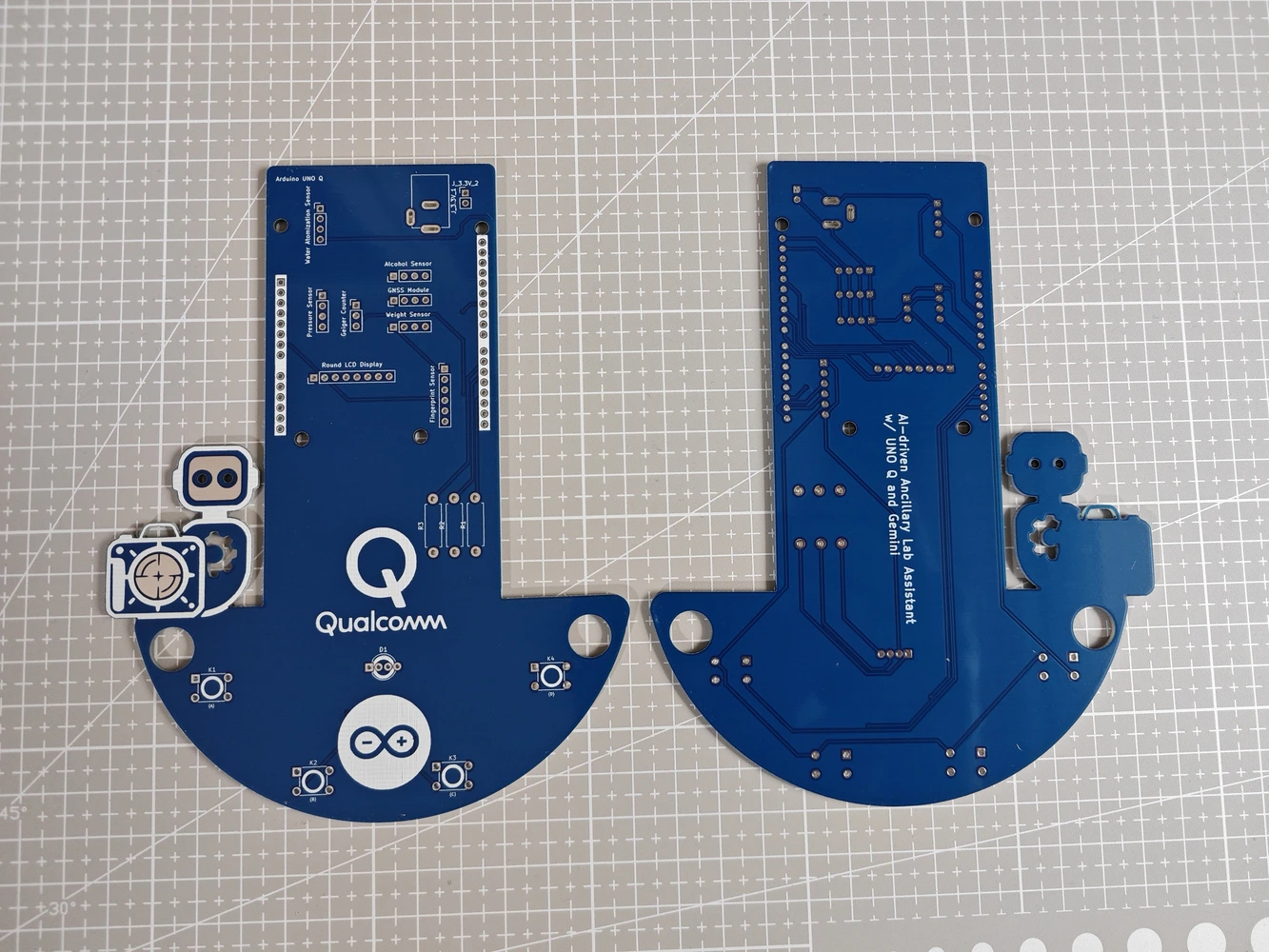
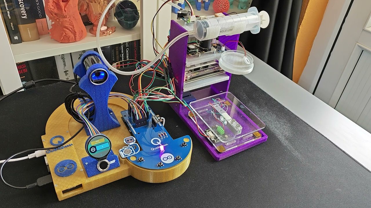
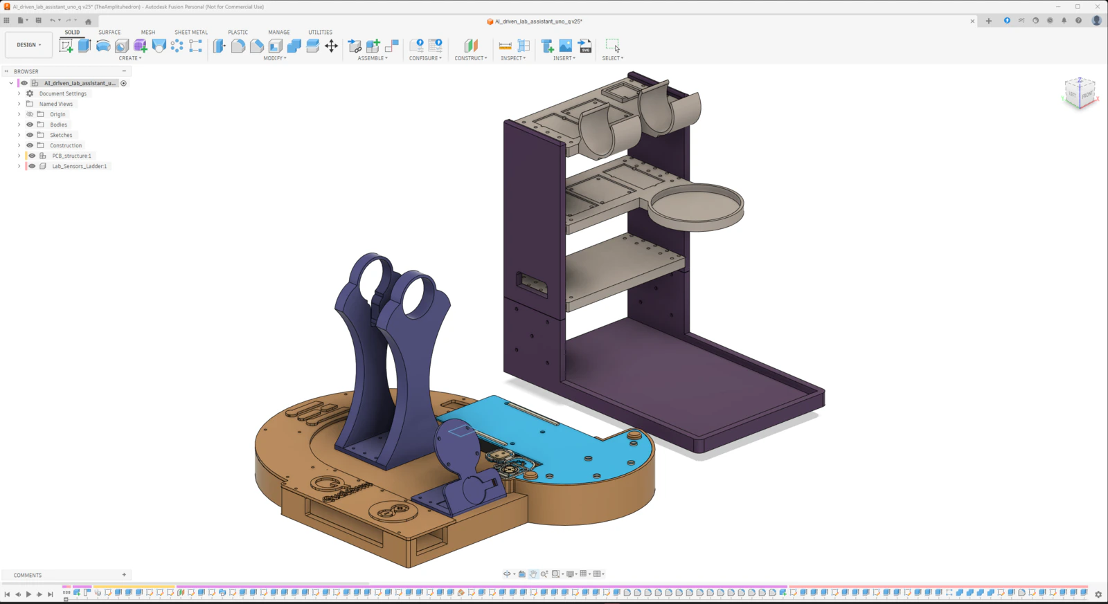
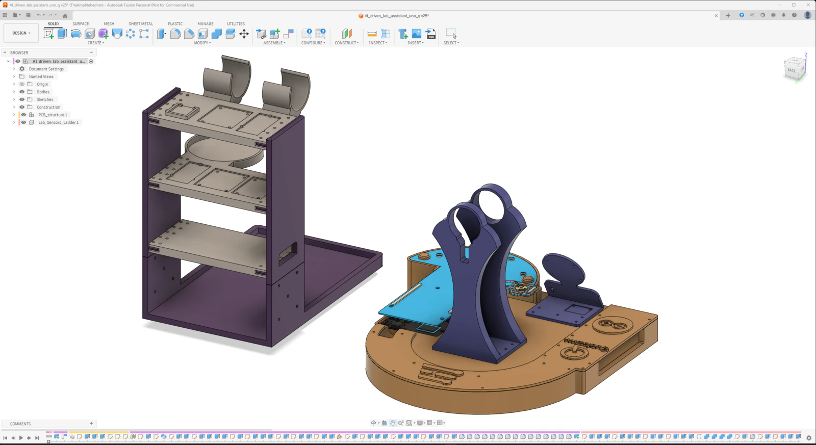
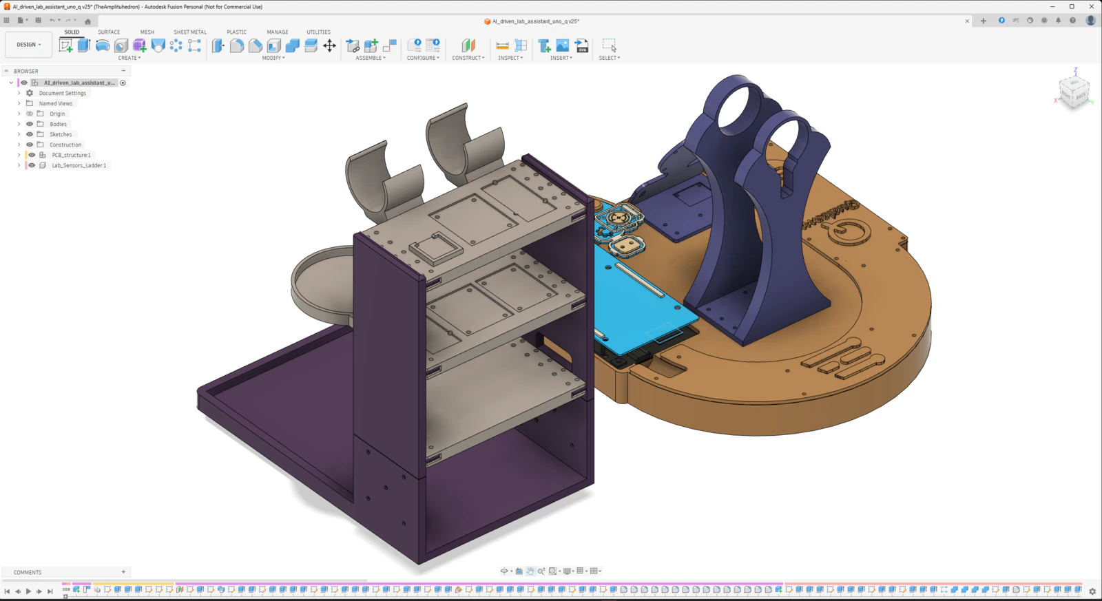
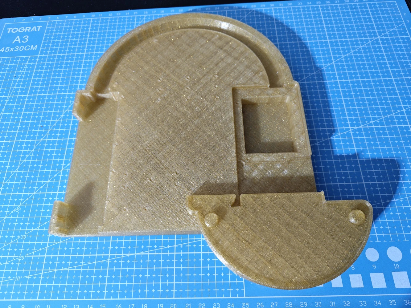
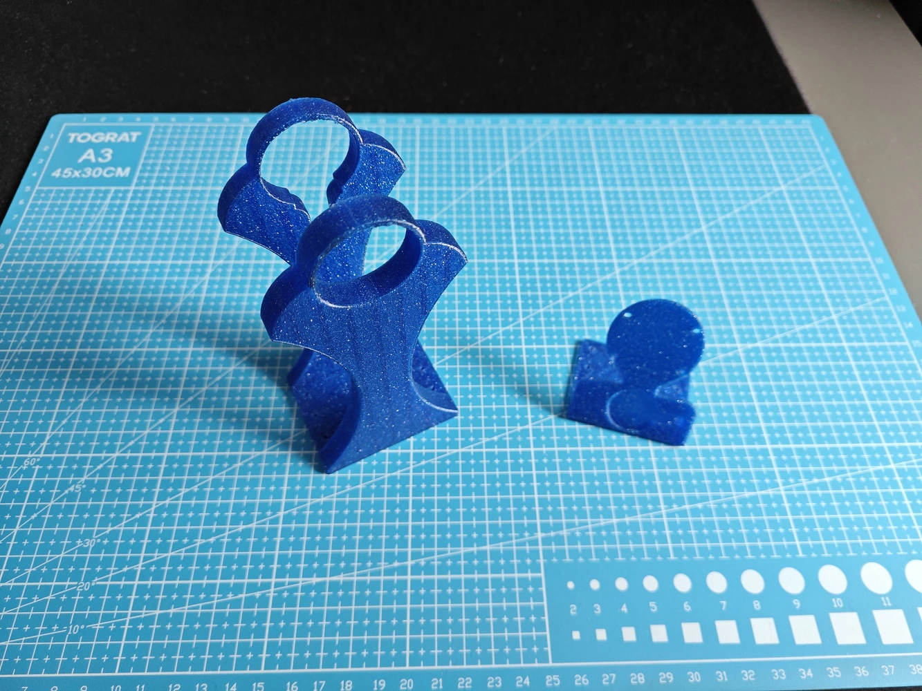
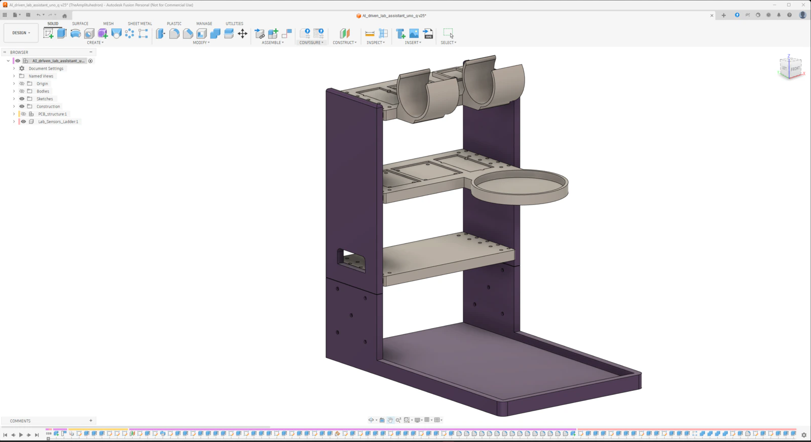
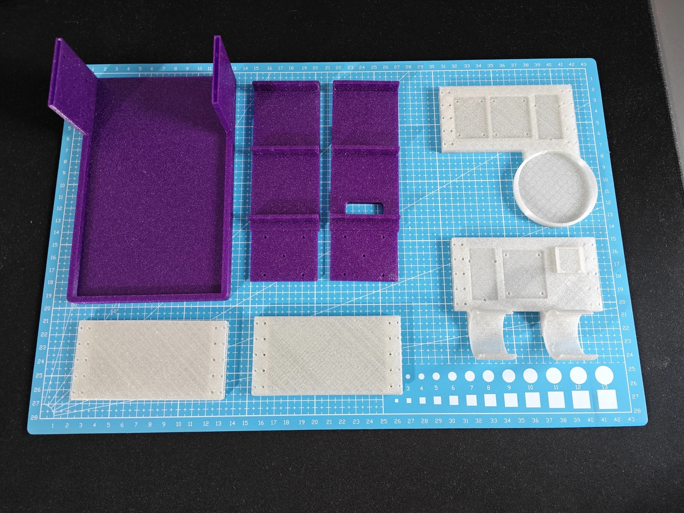
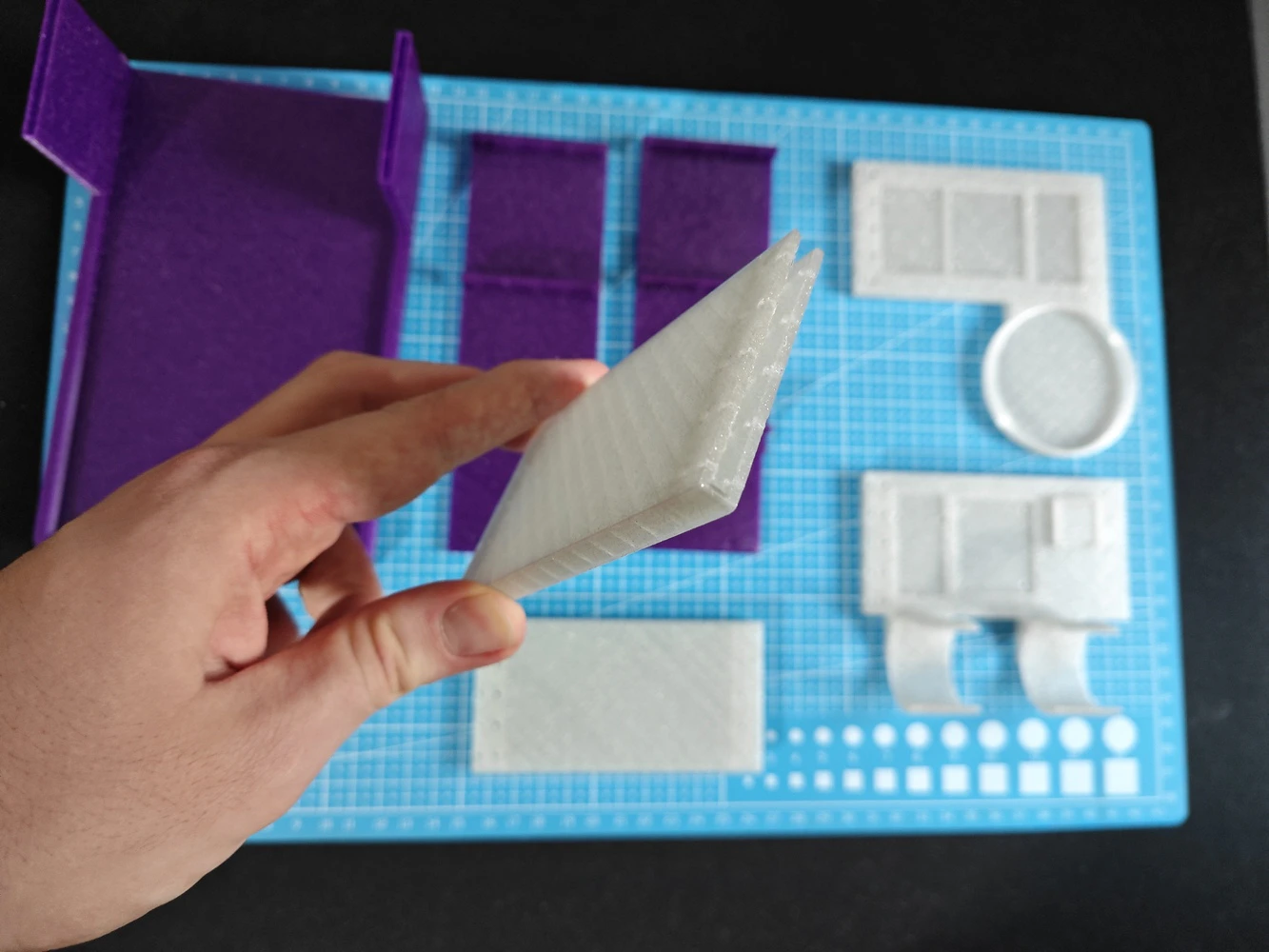
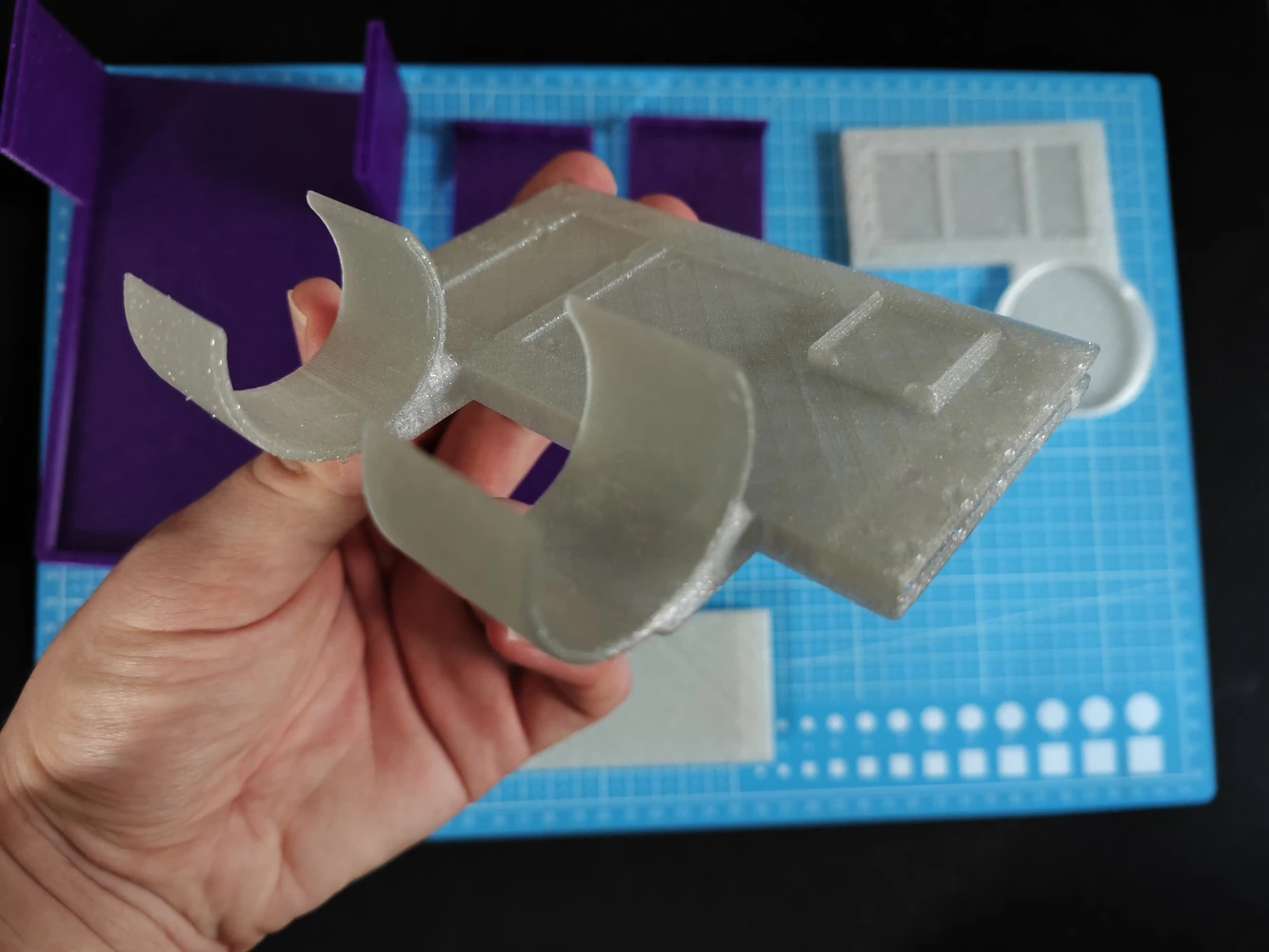
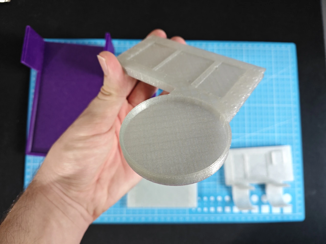
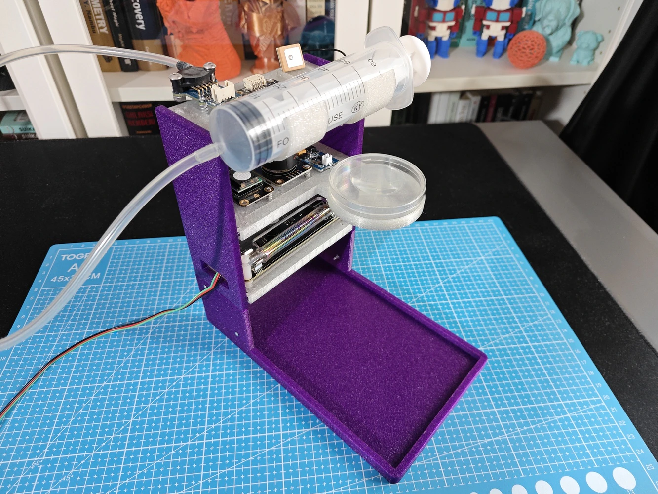
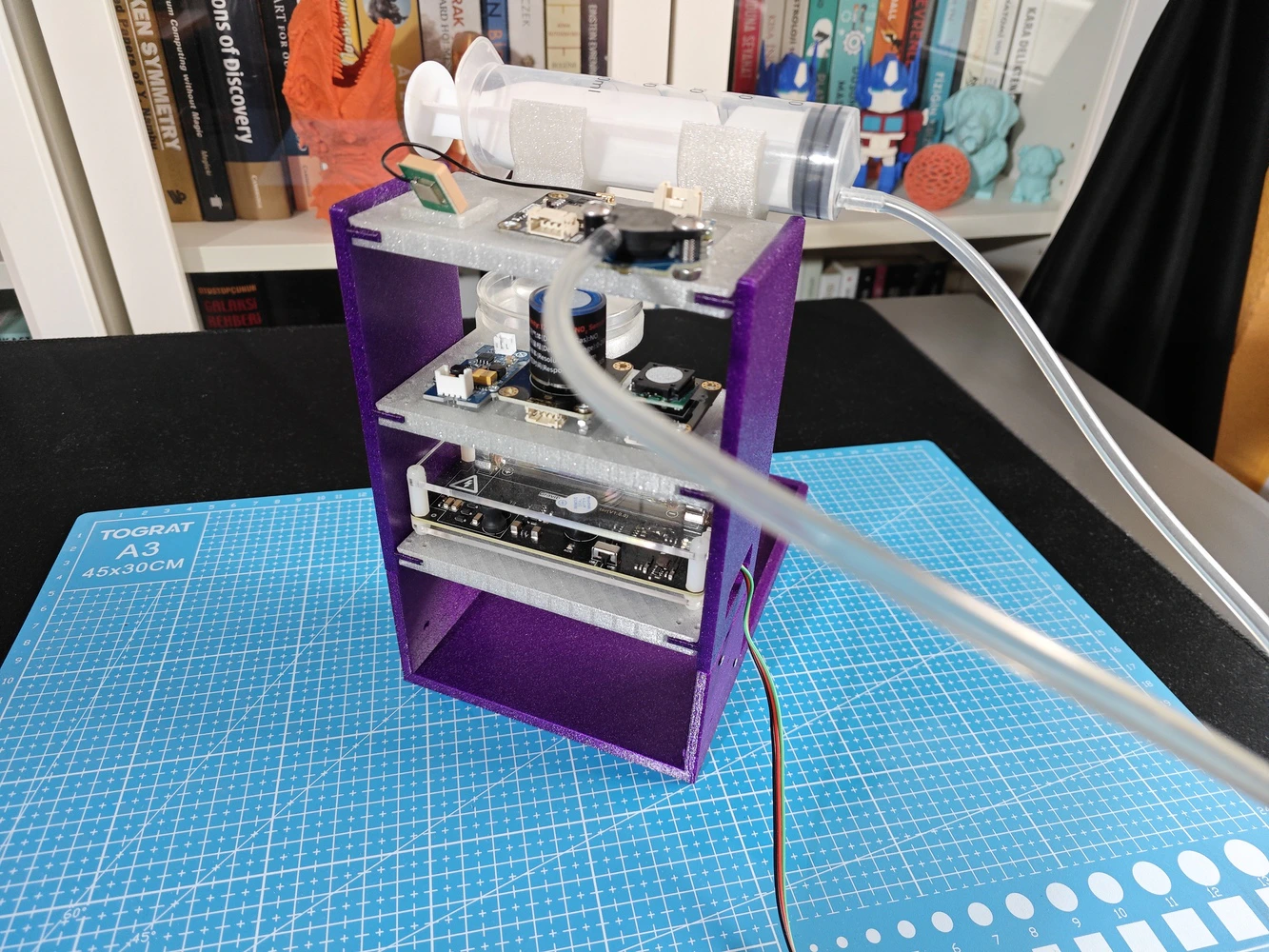
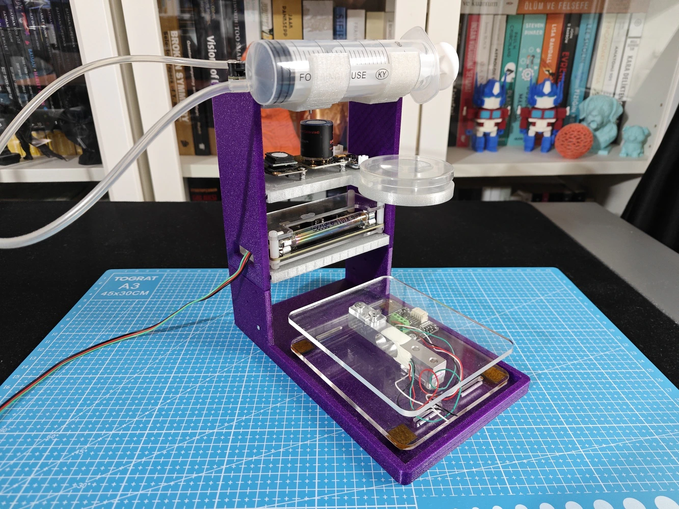
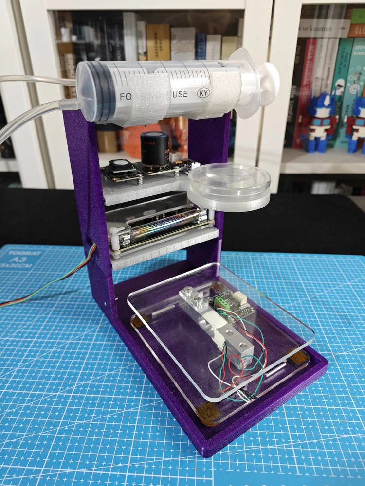
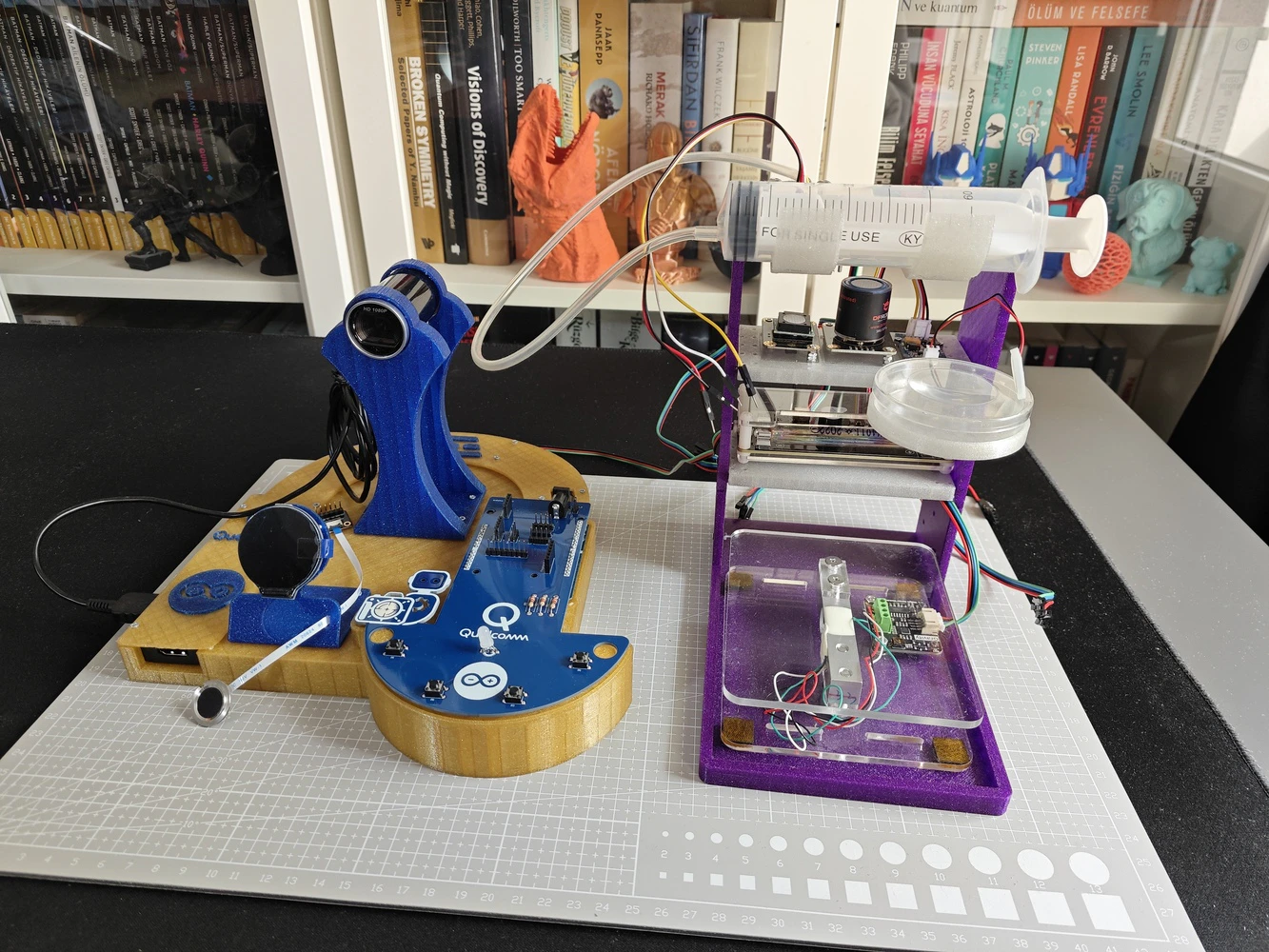
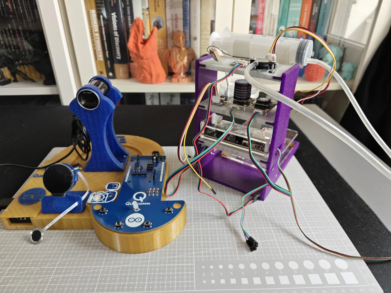
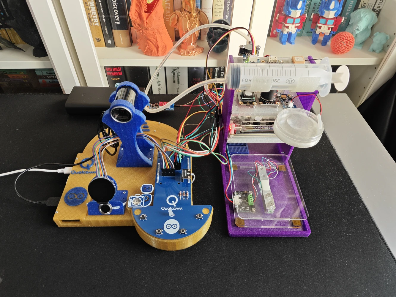
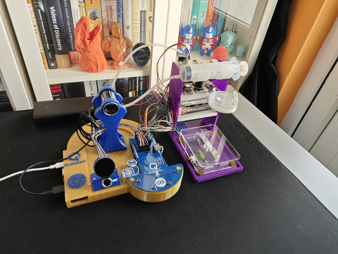
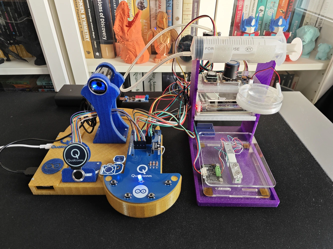
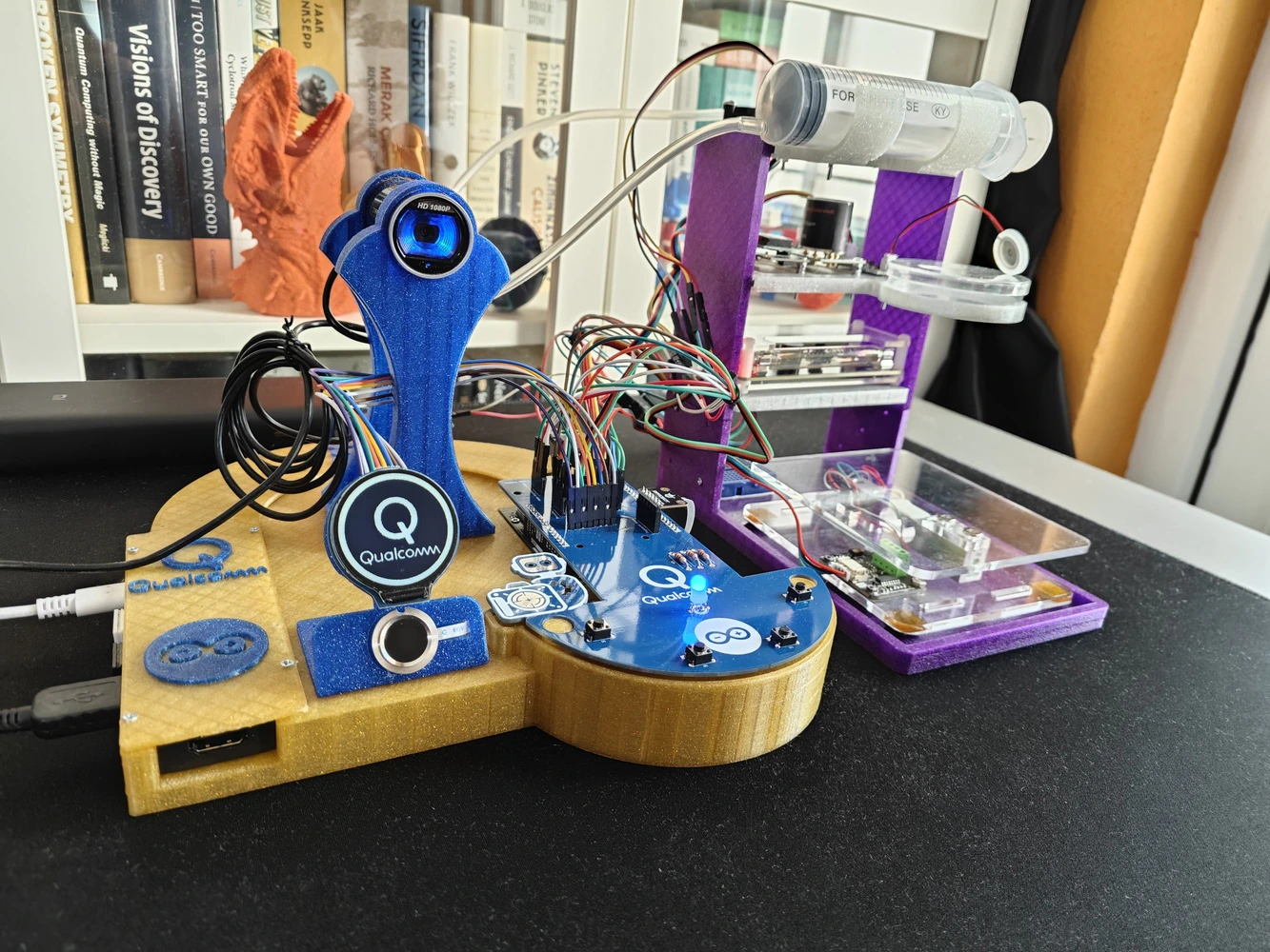
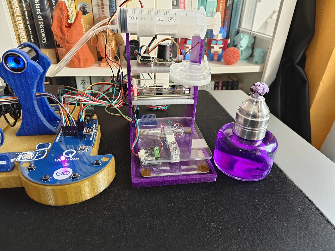
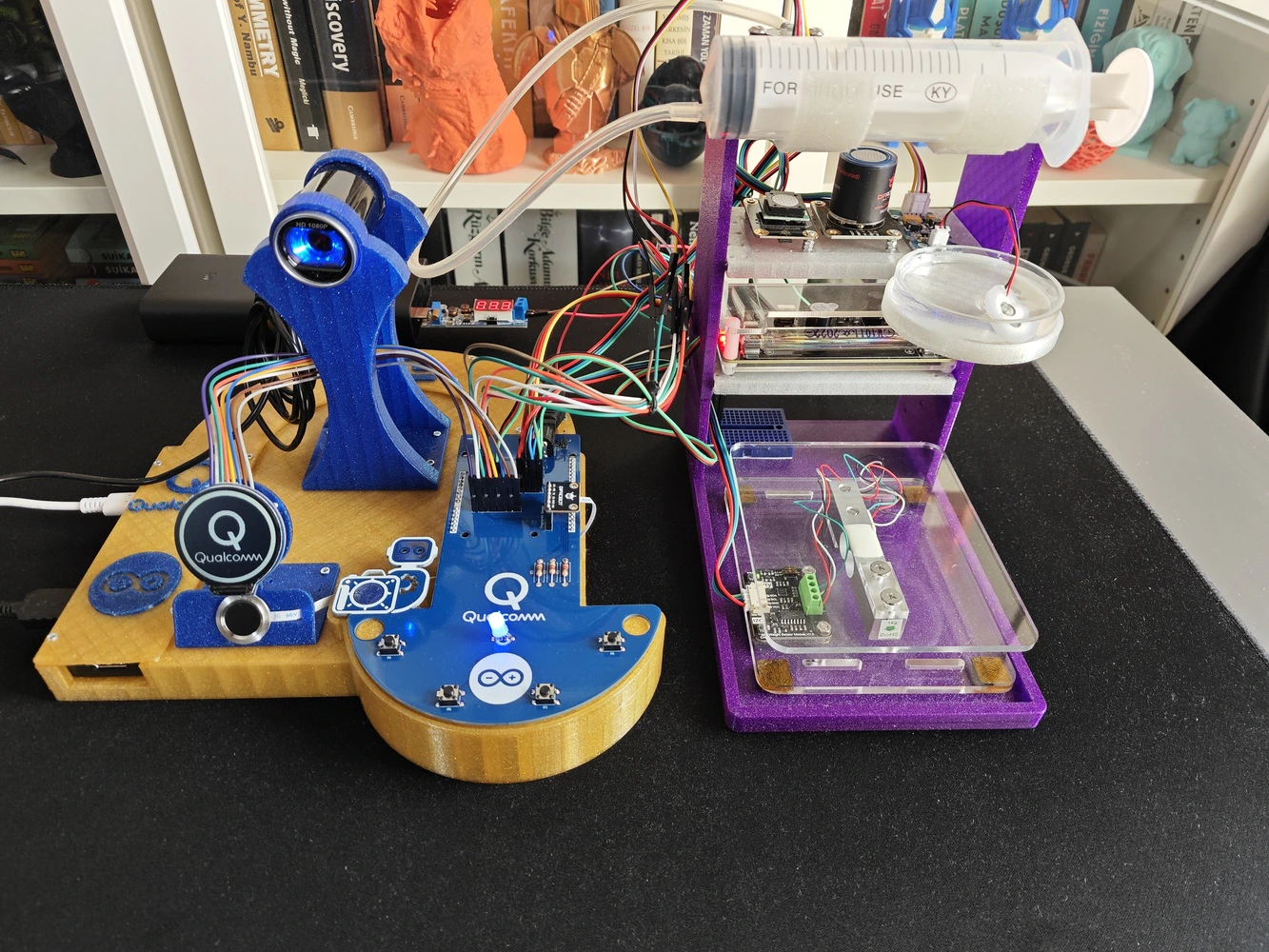
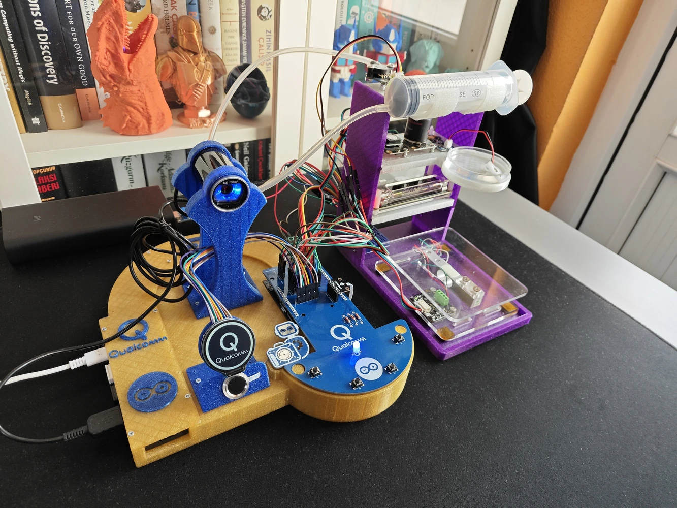
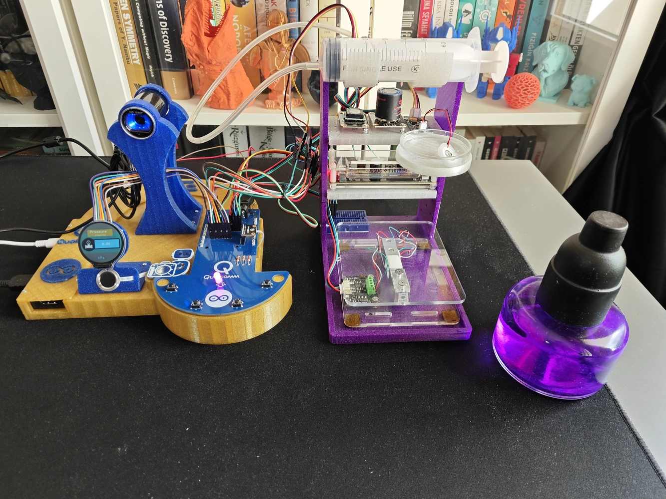
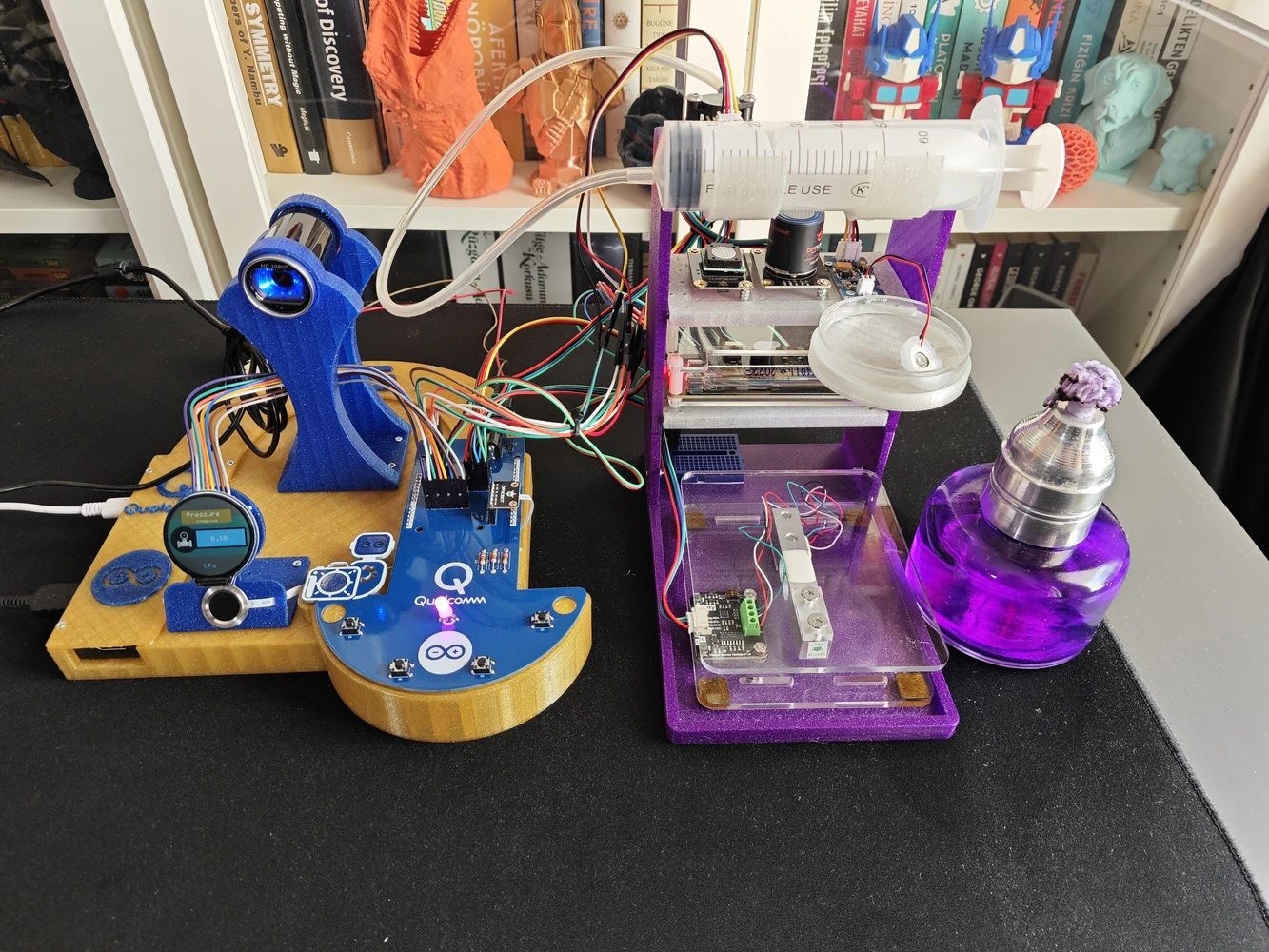
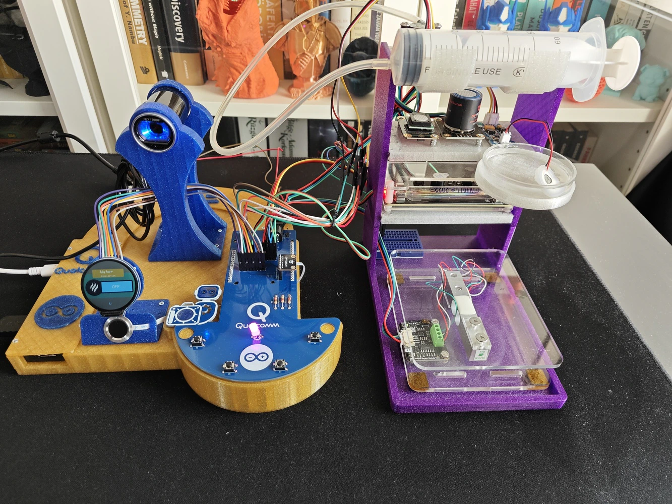
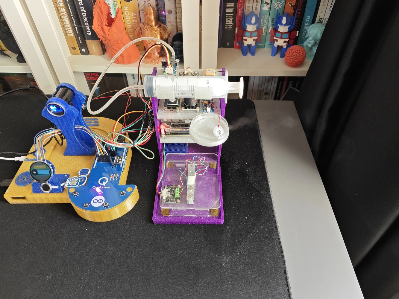
Step 9: Modeling the ancillary lab assistant 3D components to form the final device structure
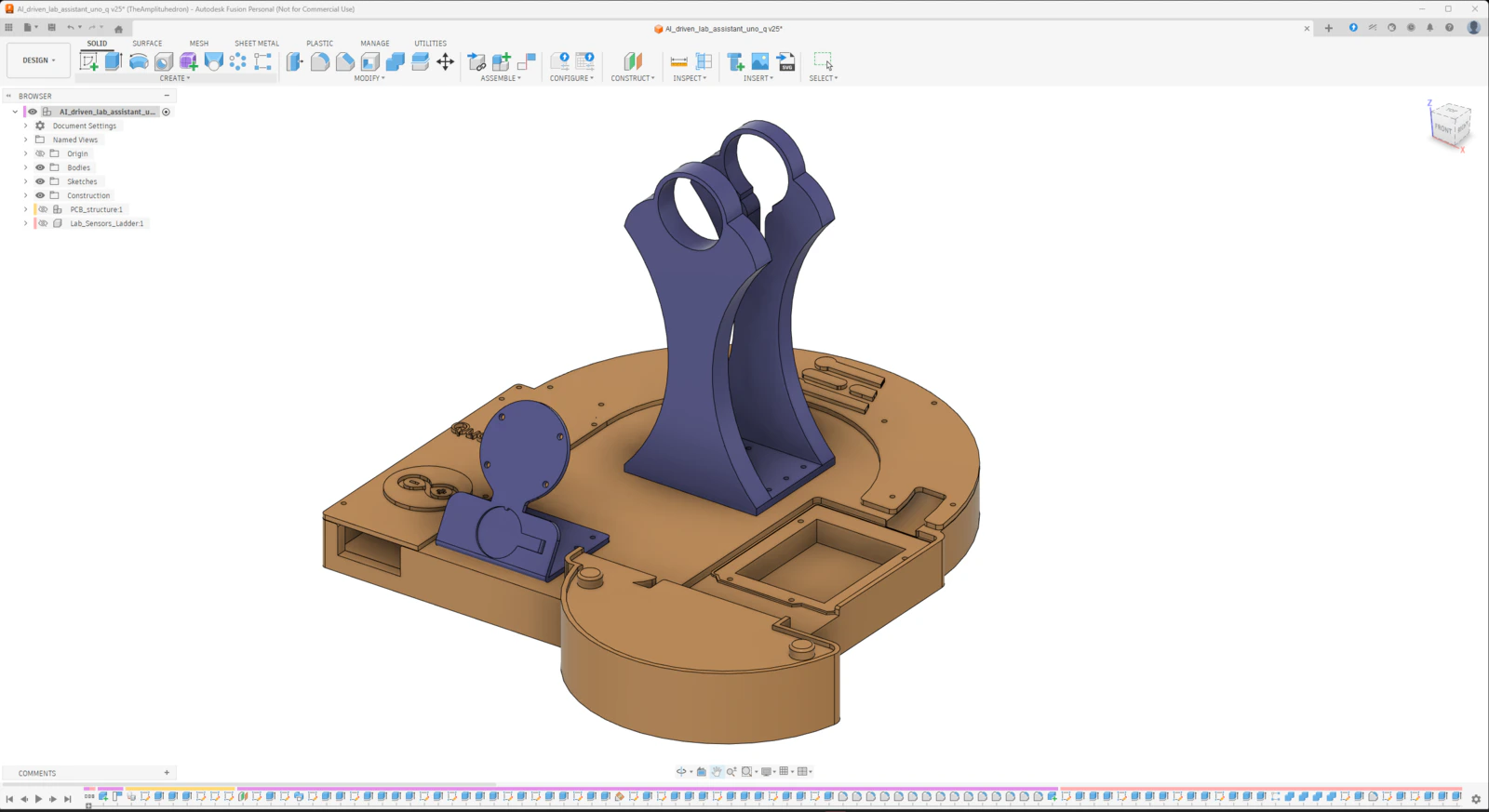
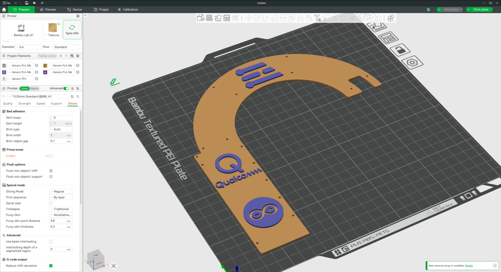
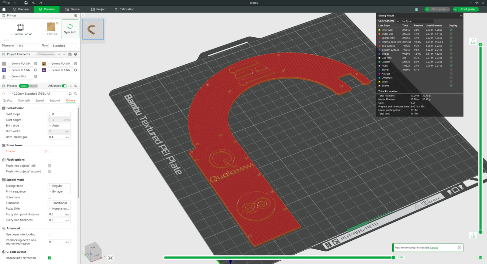
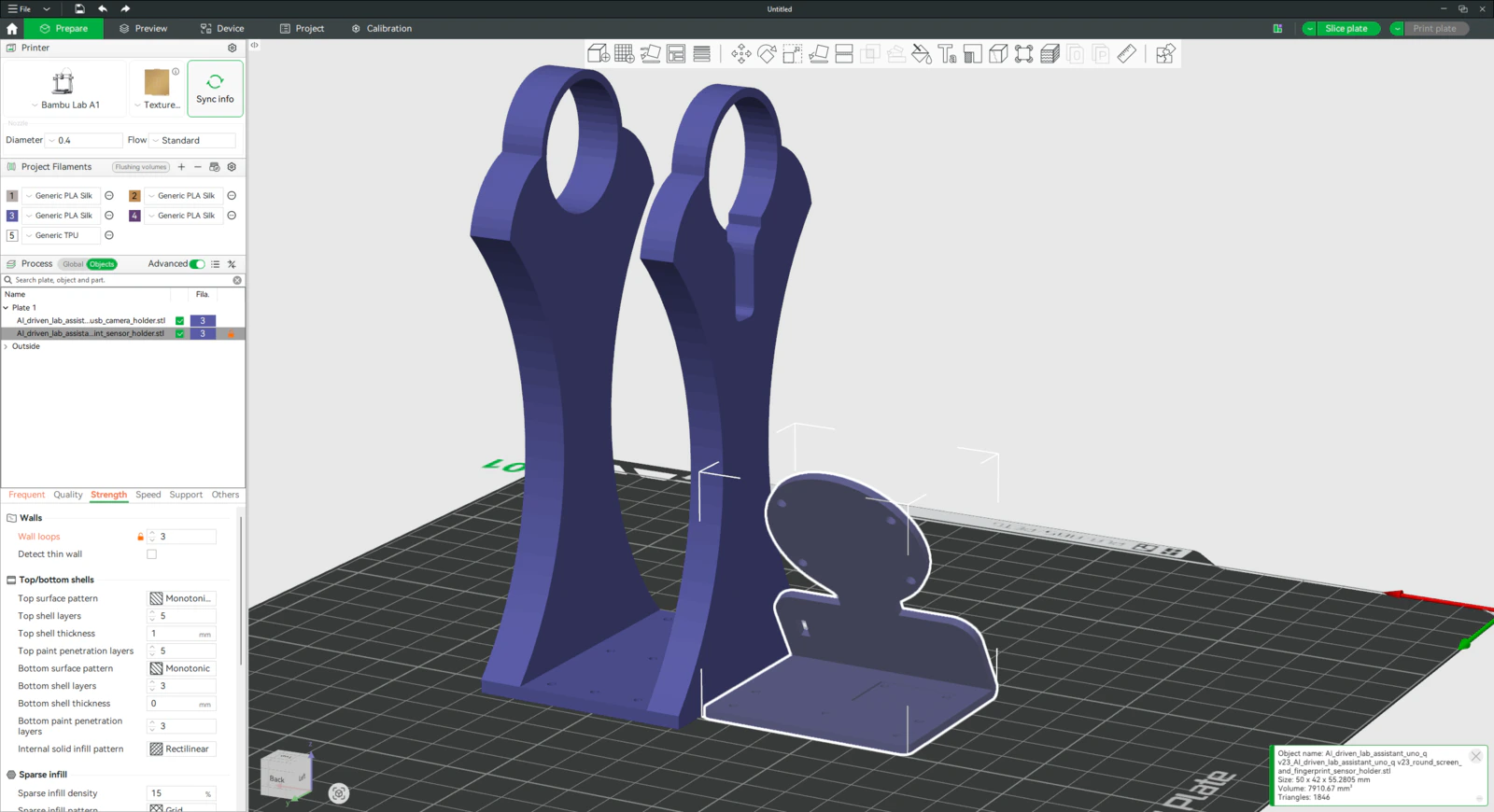
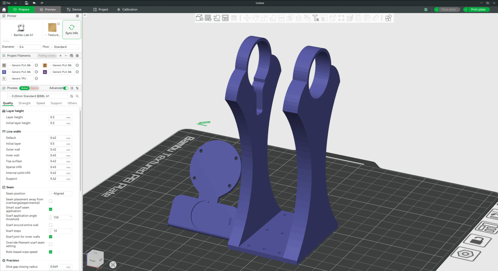
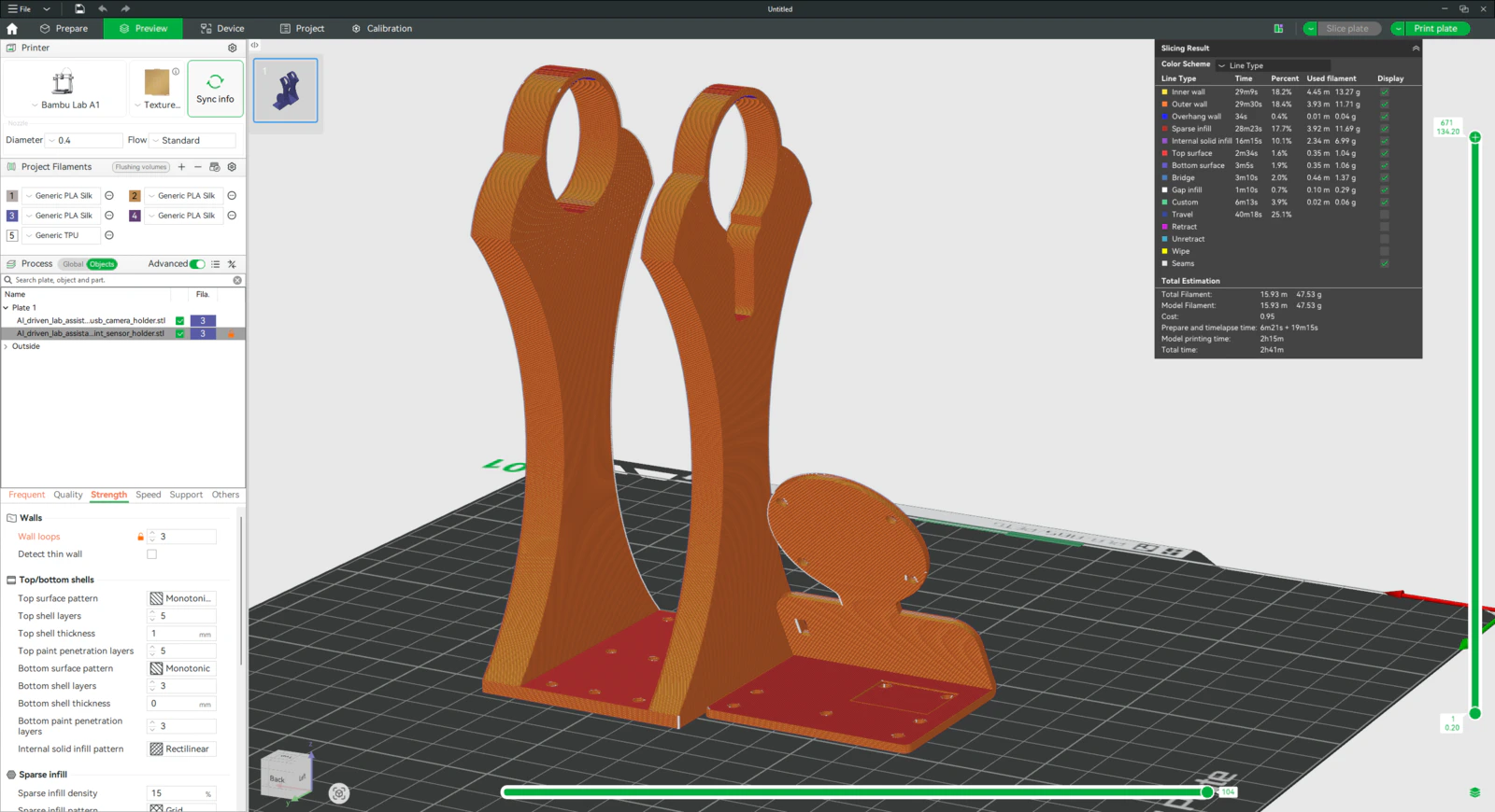
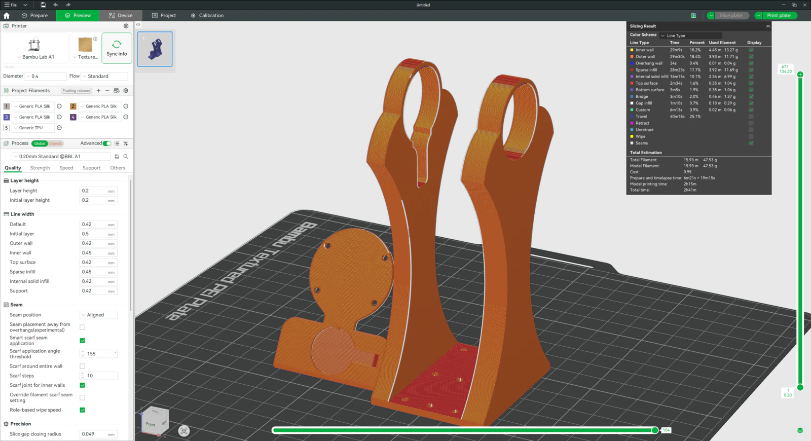
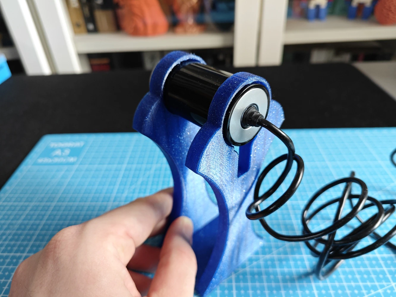
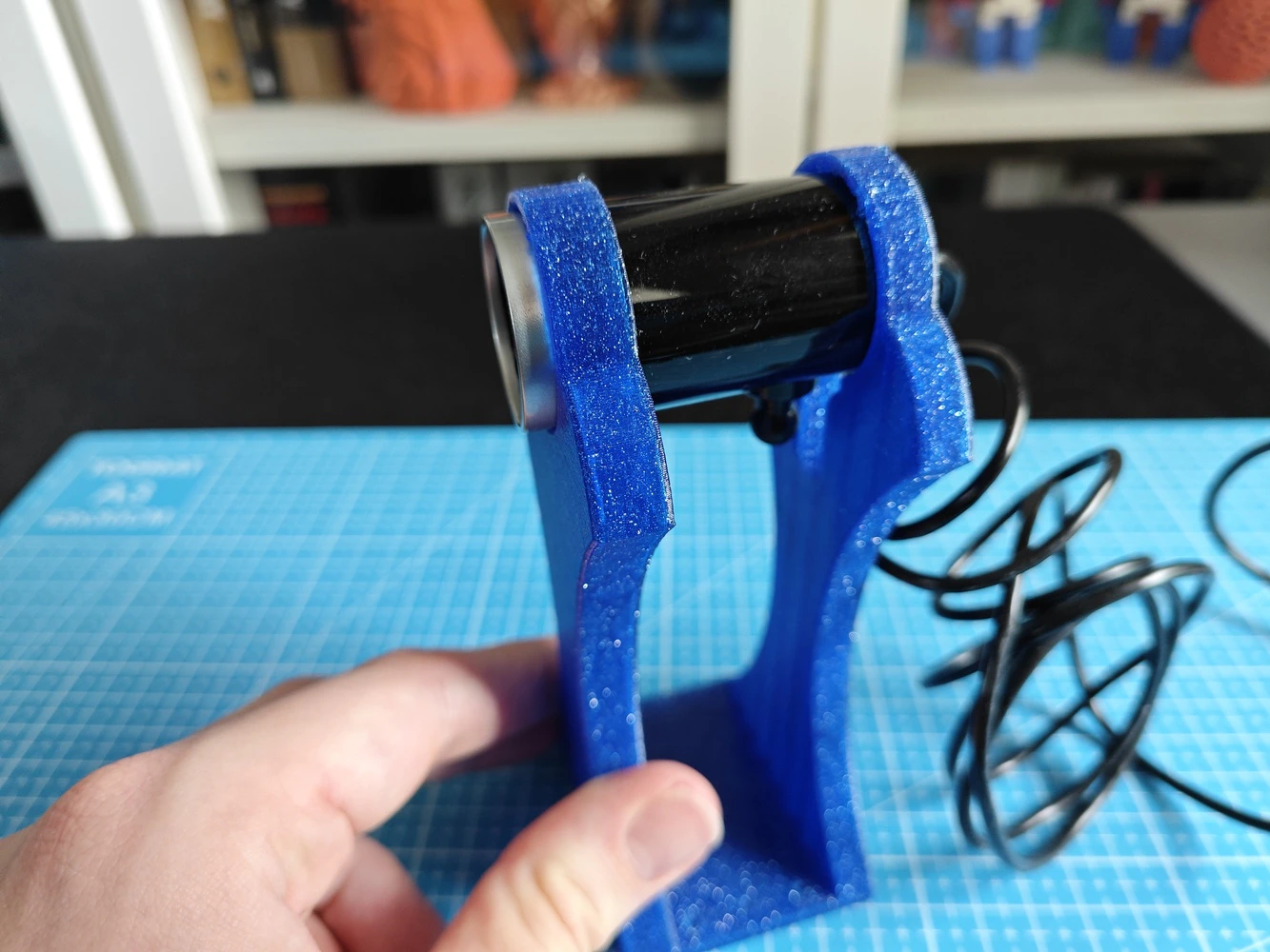
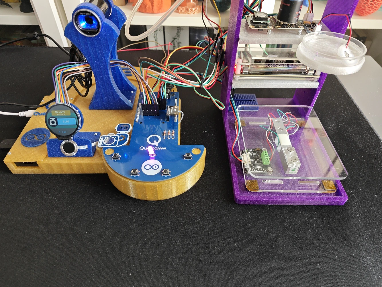
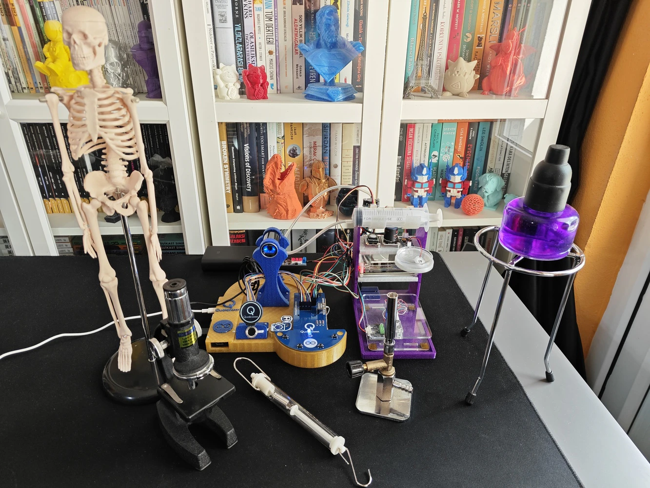
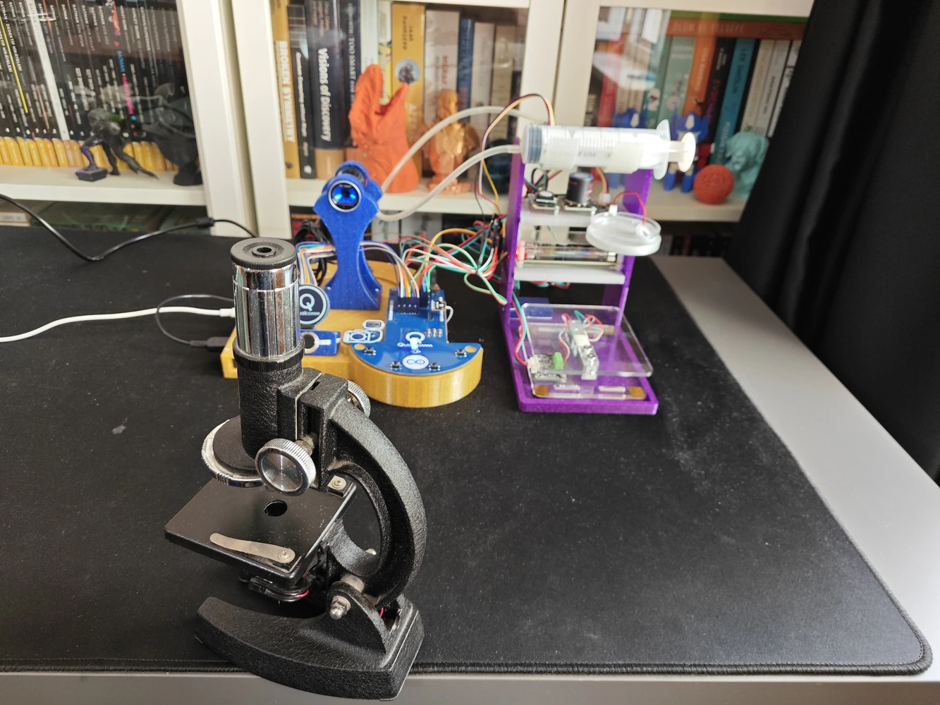
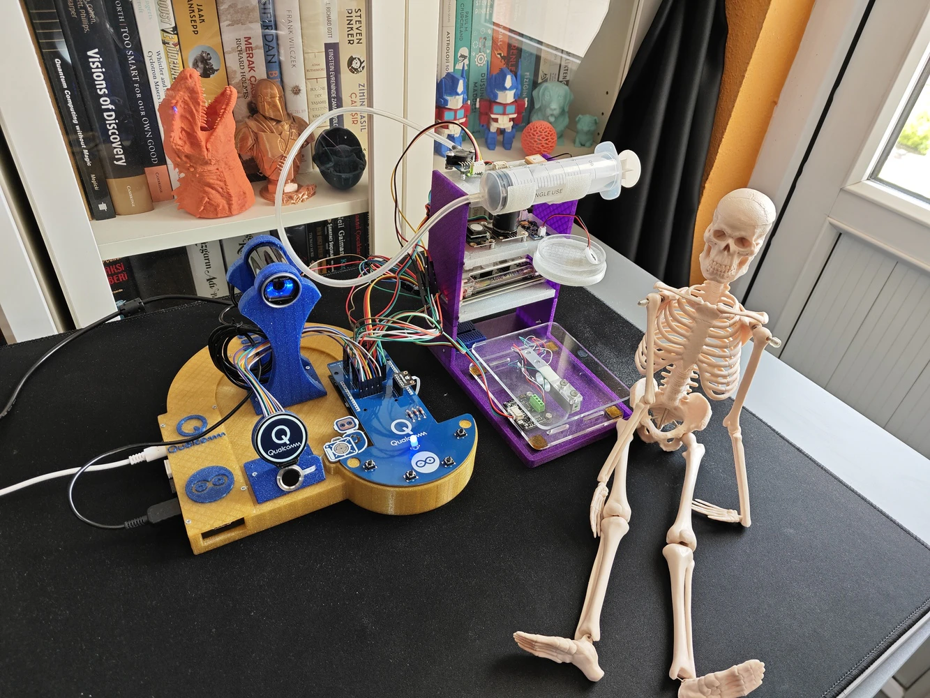
In the spirit of building a feature-rich and laboratory-worthy AI-driven ancillary lab assistant structure, I decided to design a rigid assistant base and a modular lab sensor ladder from the ground up, including a dedicated USB camera stand. As a frame of reference for those who aim to replicate or improve this ancillary lab assistant, I shared the design files (STL) of all 3D components as open-source on the project GitHub repository. 🎨 I sliced all the exported STL files in Bambu Studio and printed them using my Bambu Lab A1 Combo. In accordance with my color theme, I utilized these PLA filaments while printing 3D parts of the lab assistant:- eSun e-Twinkling Gold
- eSun e-Twinkling Blue
- eSun e-Twinkling Purple
- eSun e-Twinkling Silver
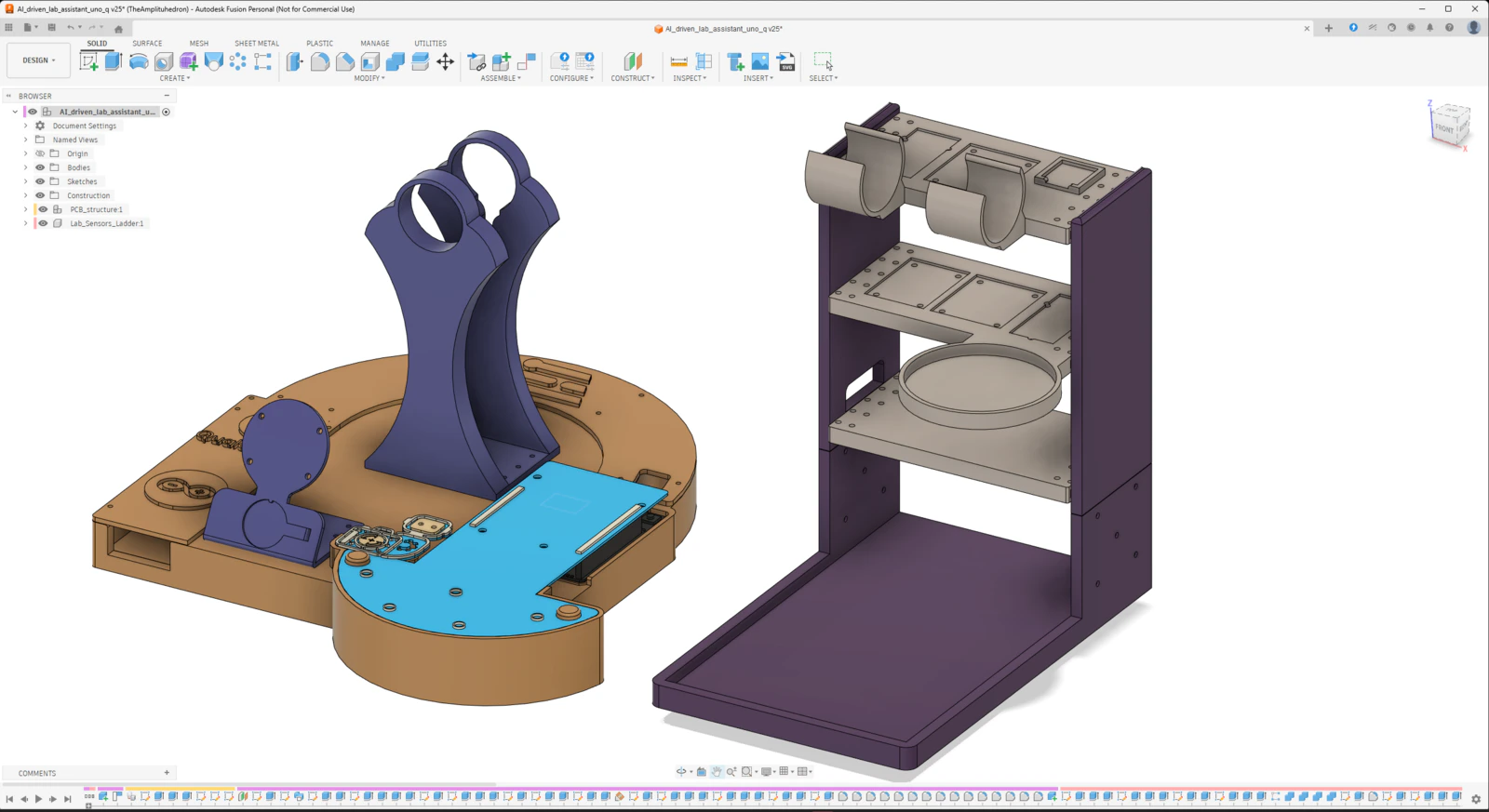
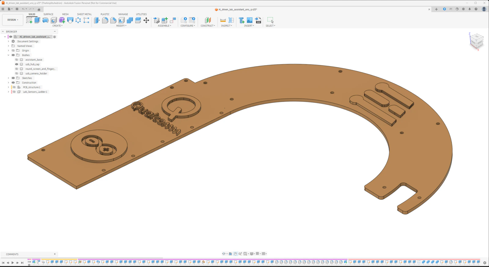
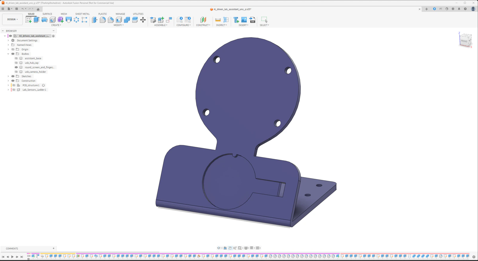
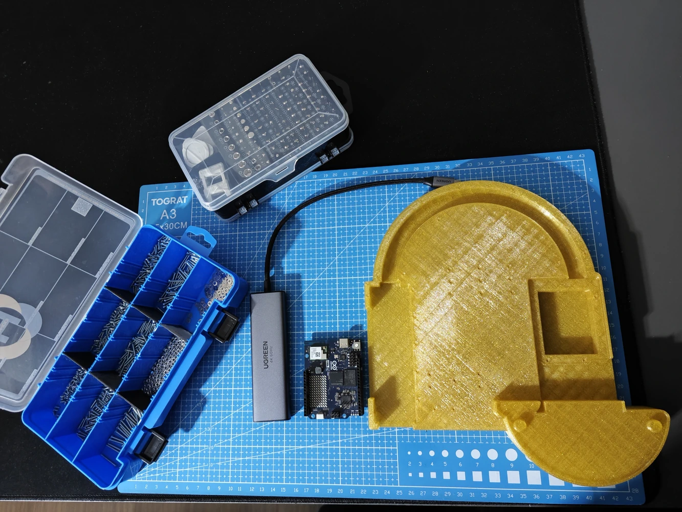
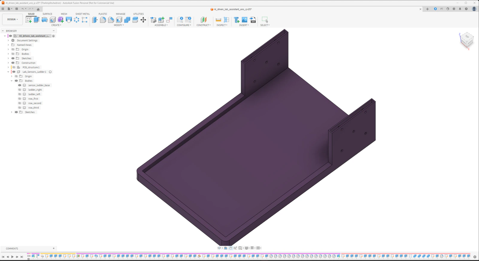
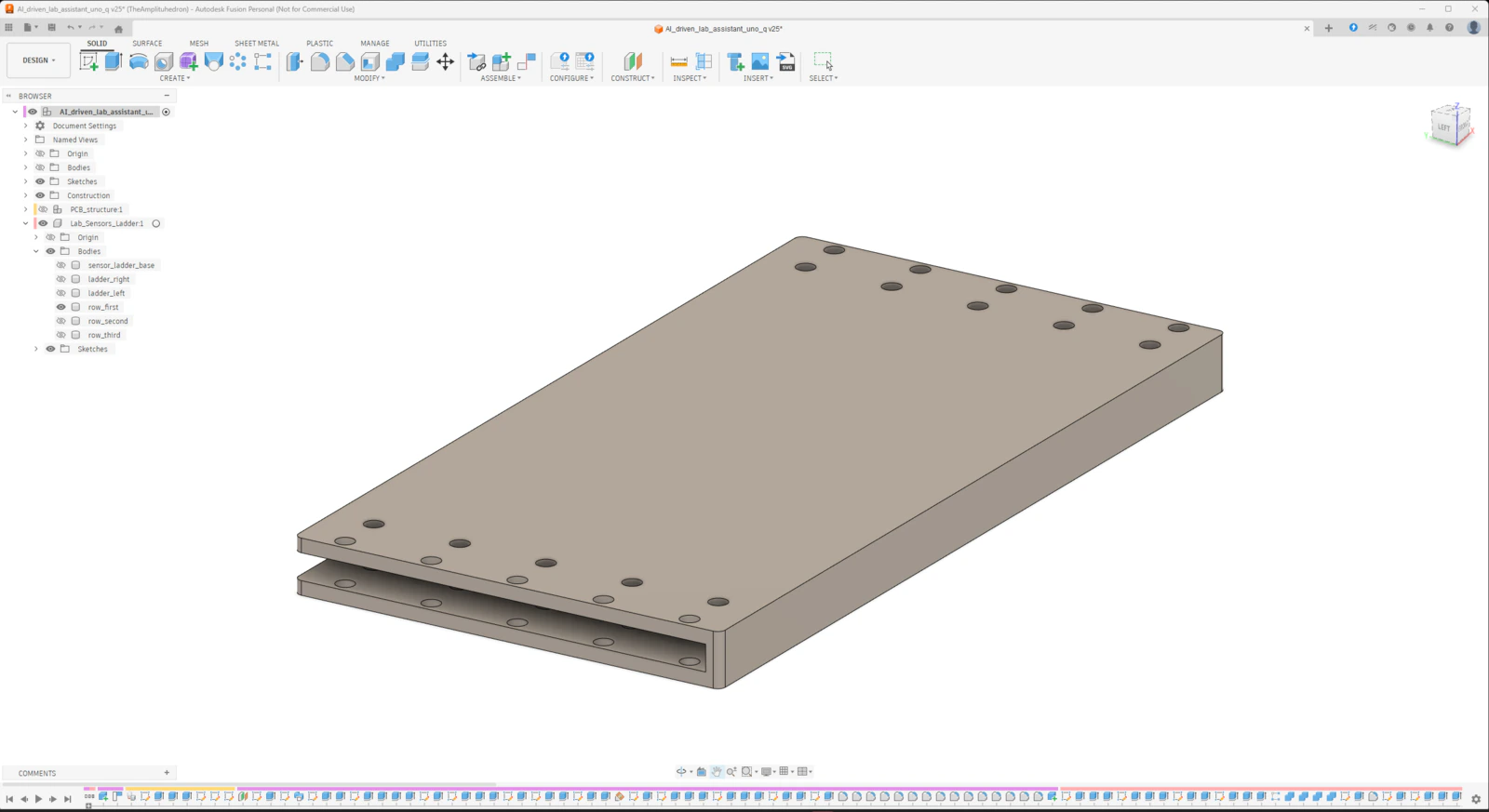
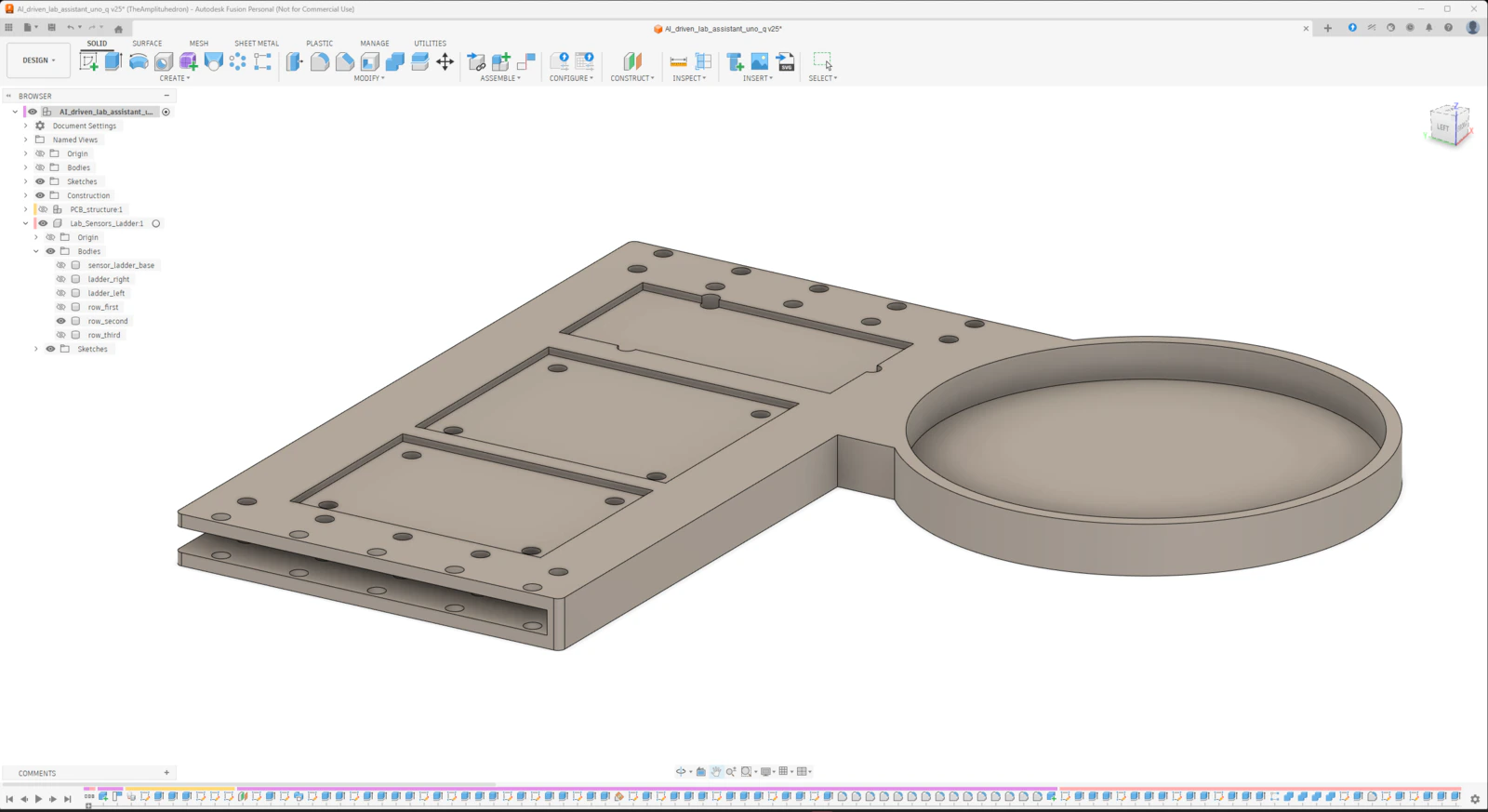
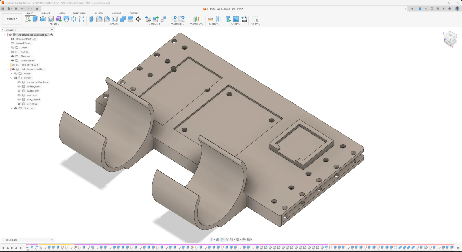
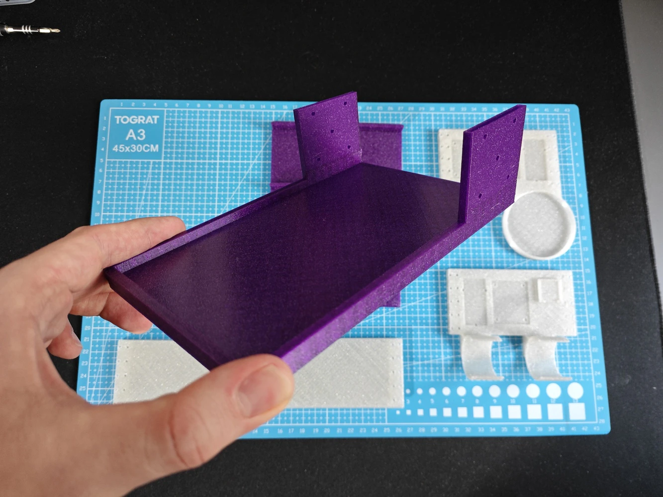
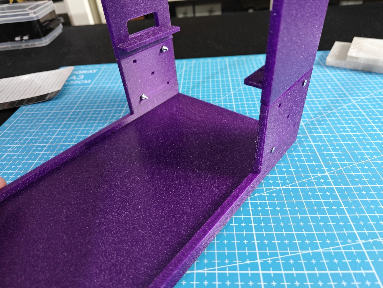
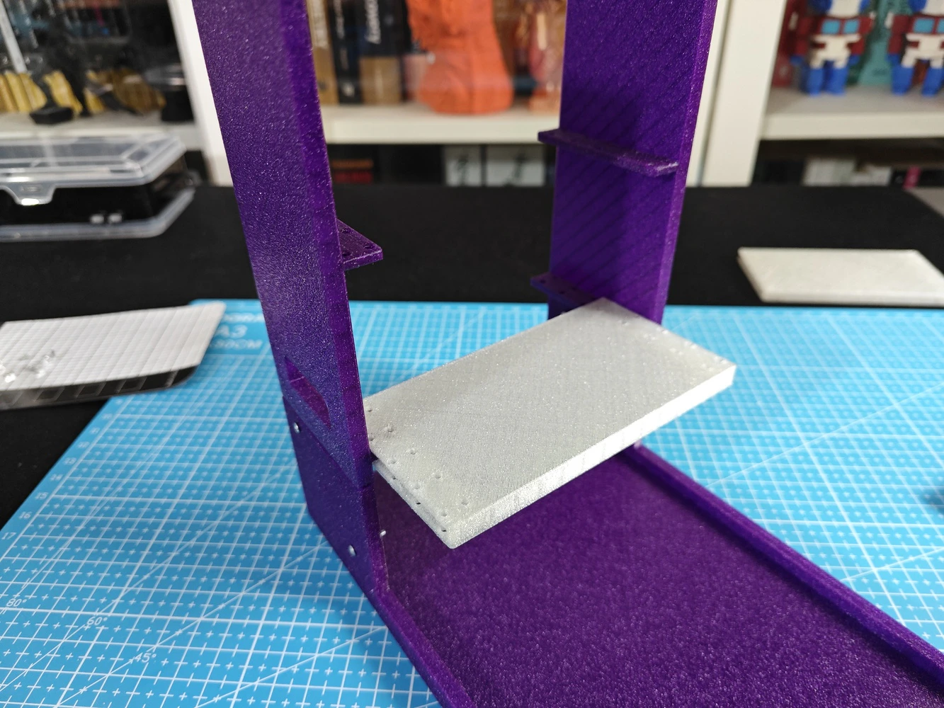
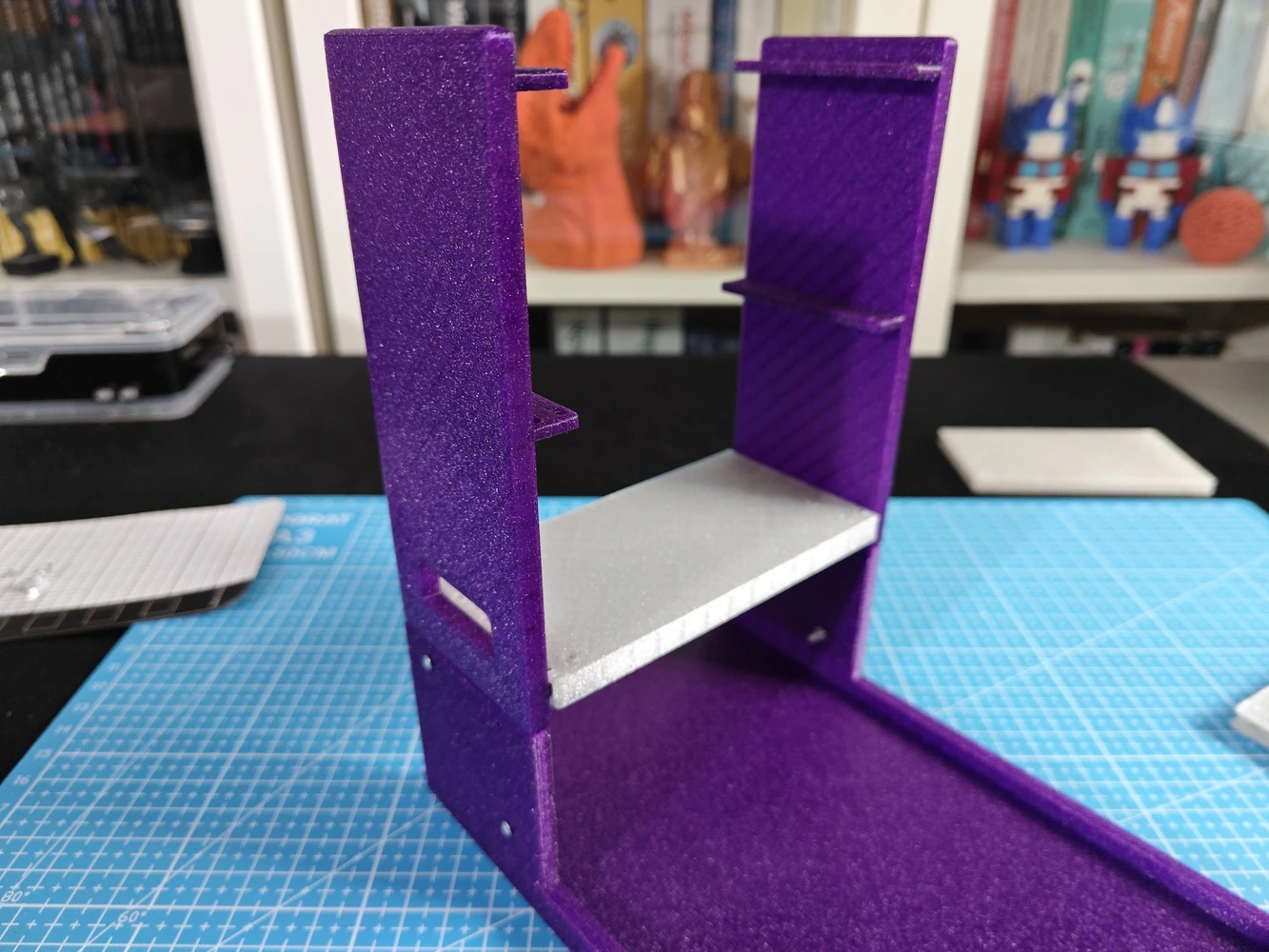
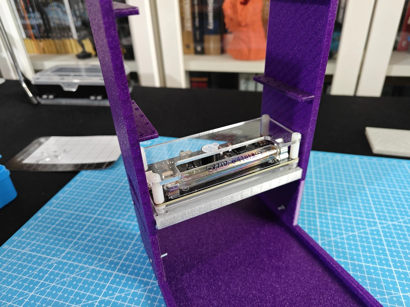
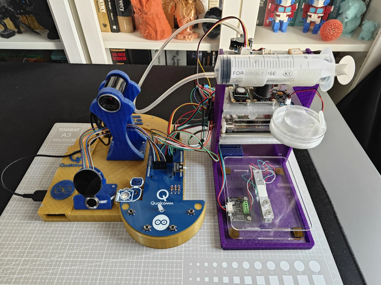
Step 9.a: Designing the base of the ancillary lab assistant
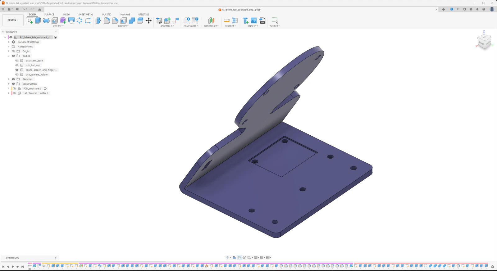
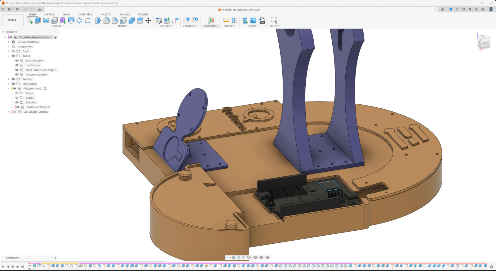
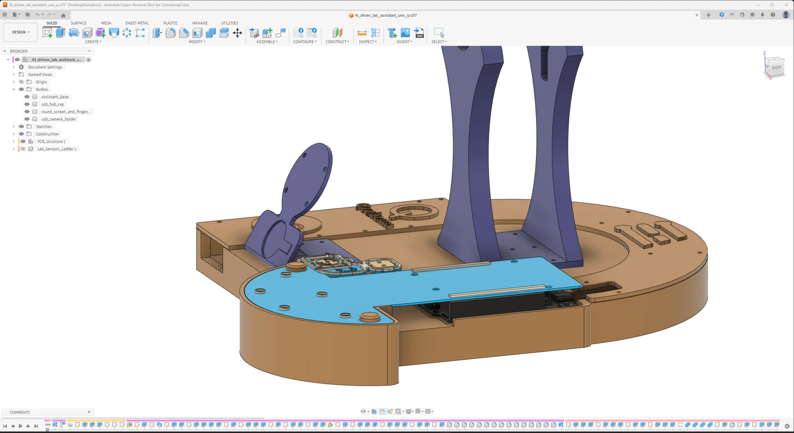
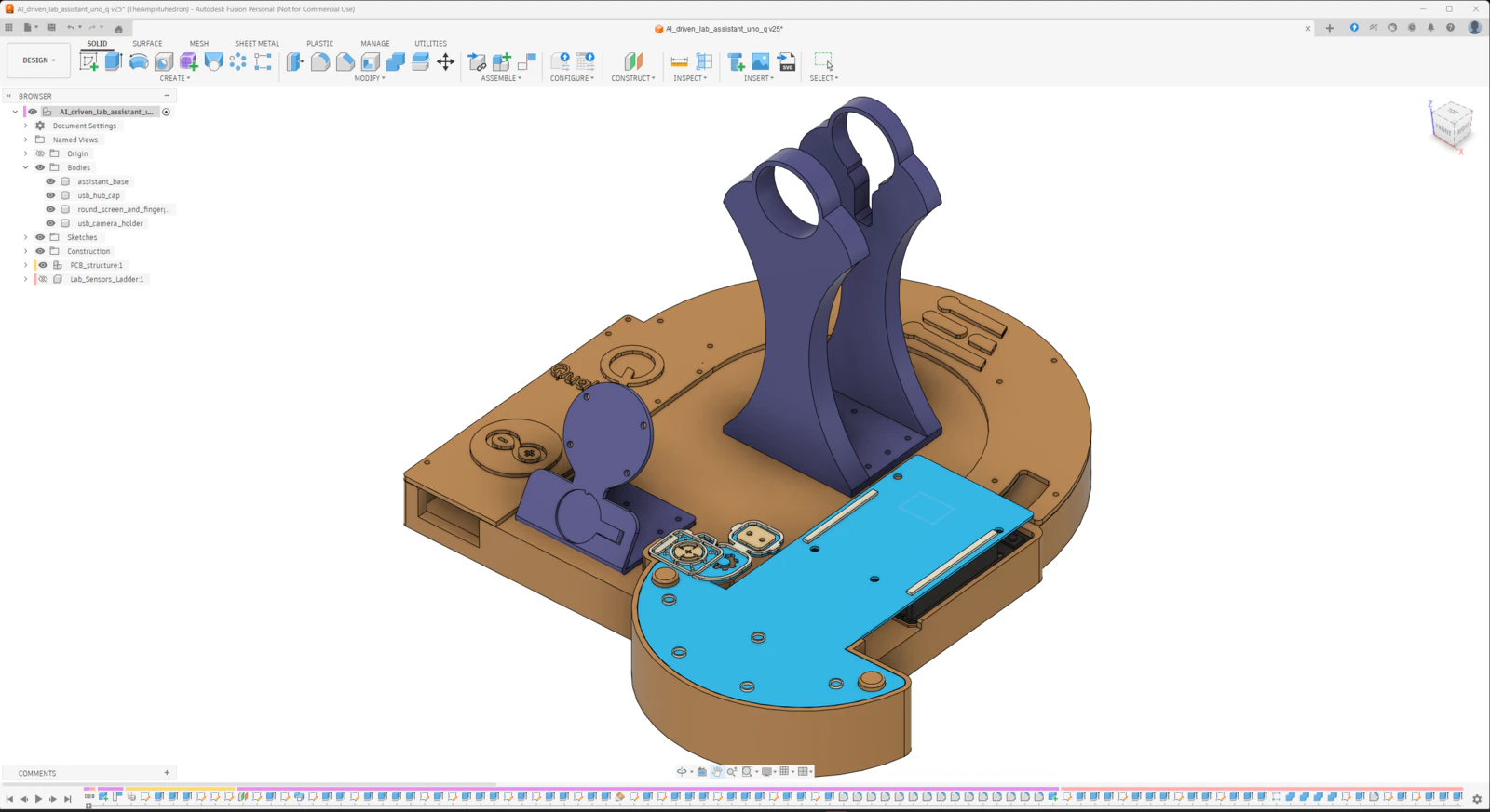
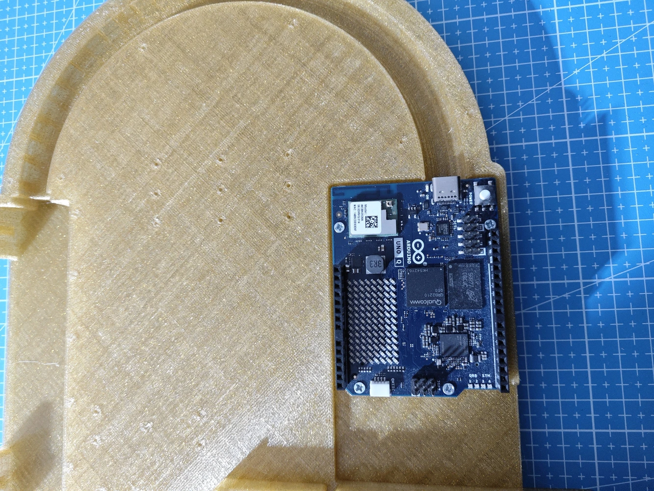
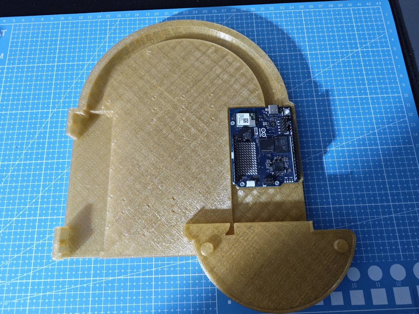
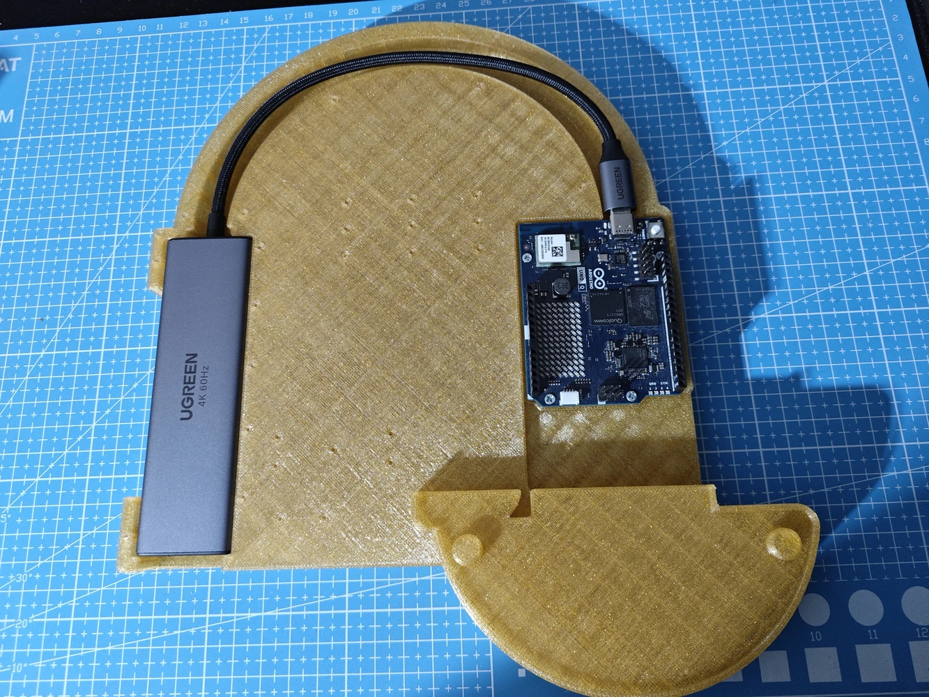
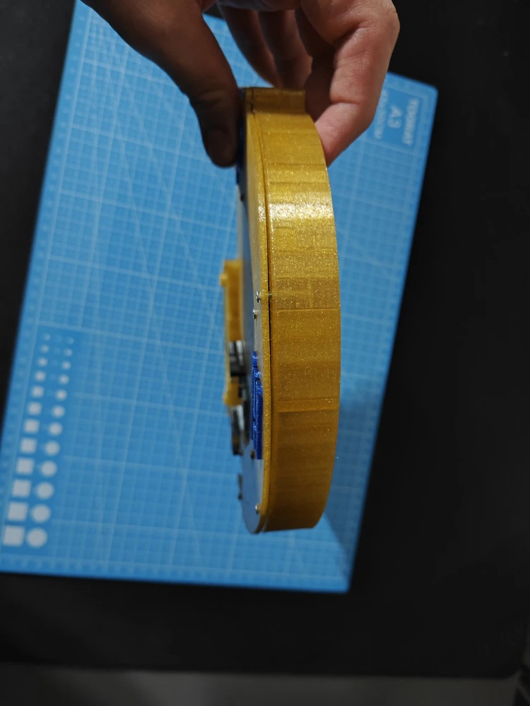
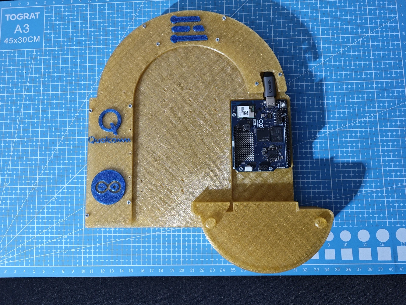
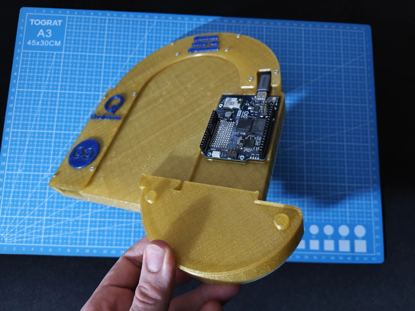
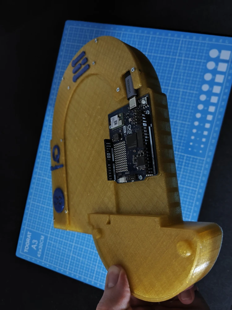
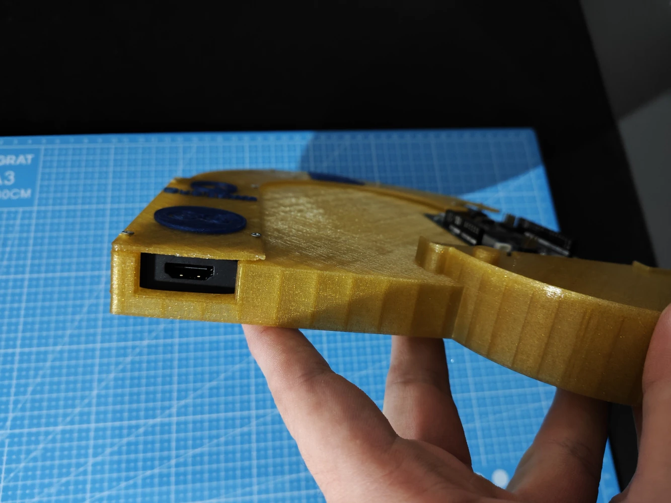
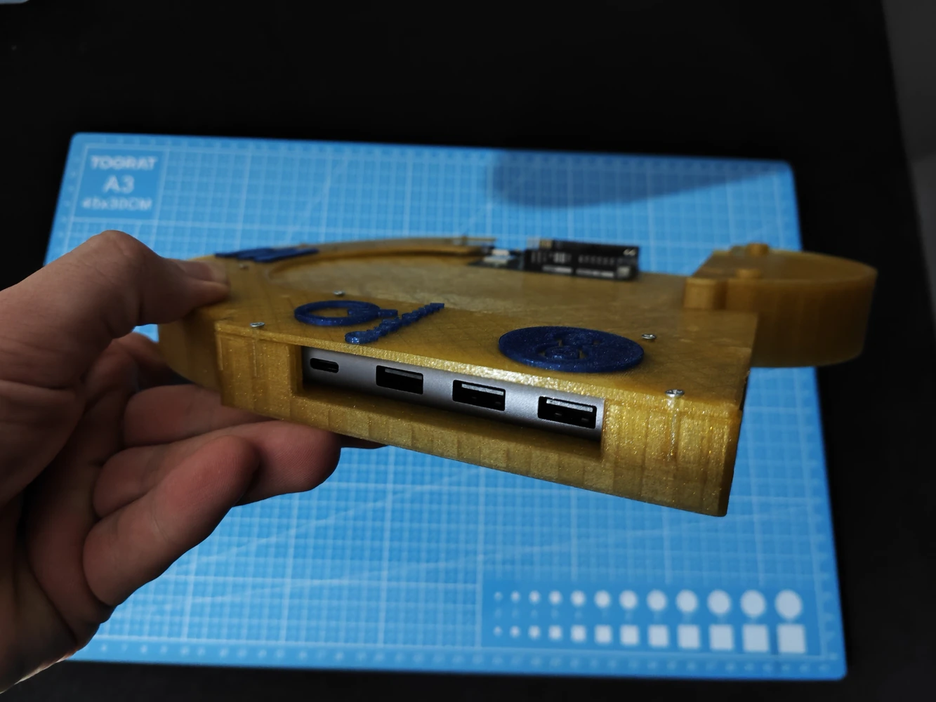
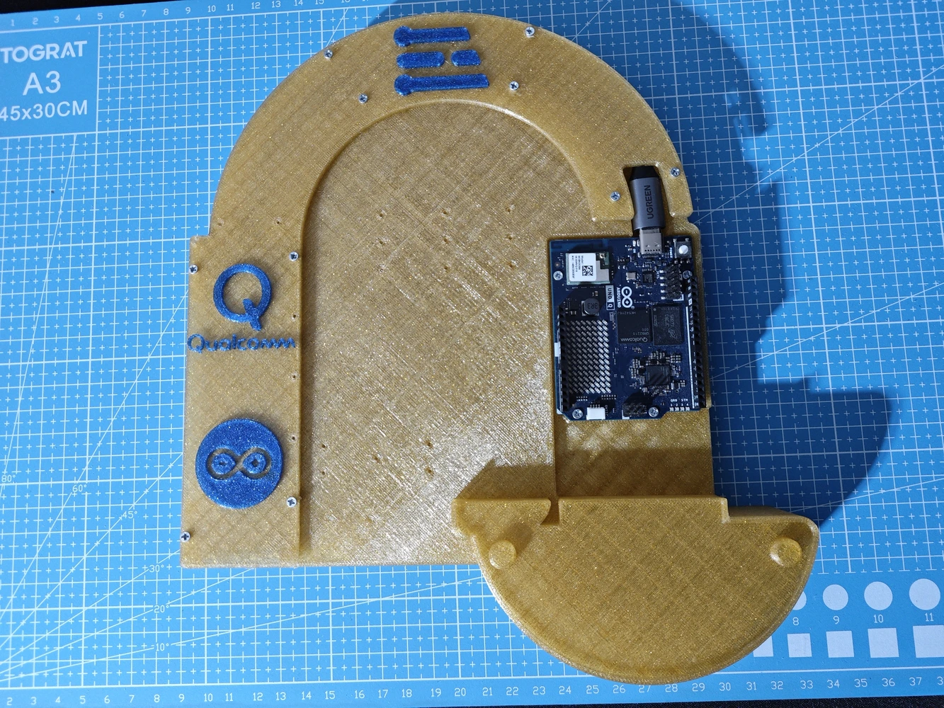
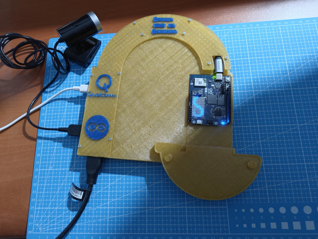
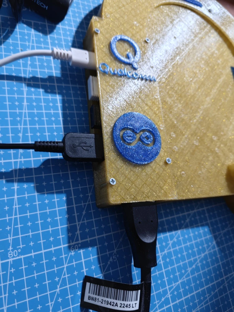
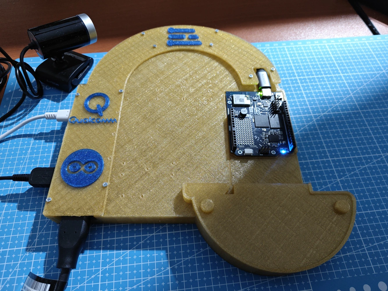
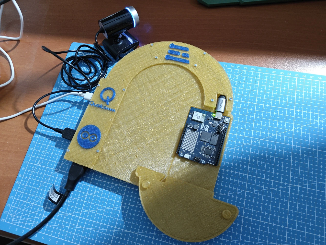
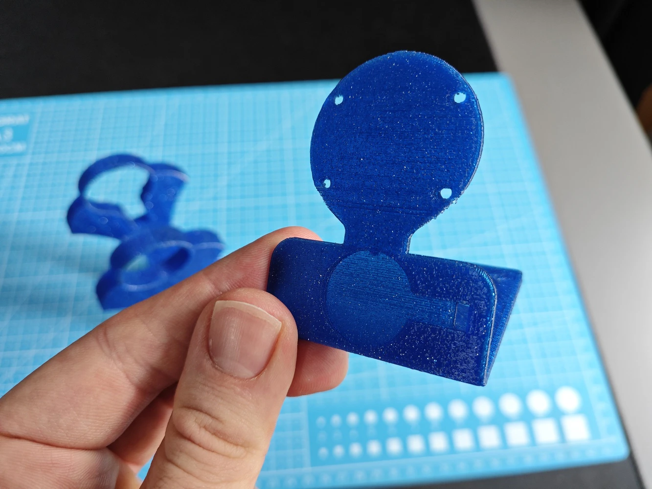
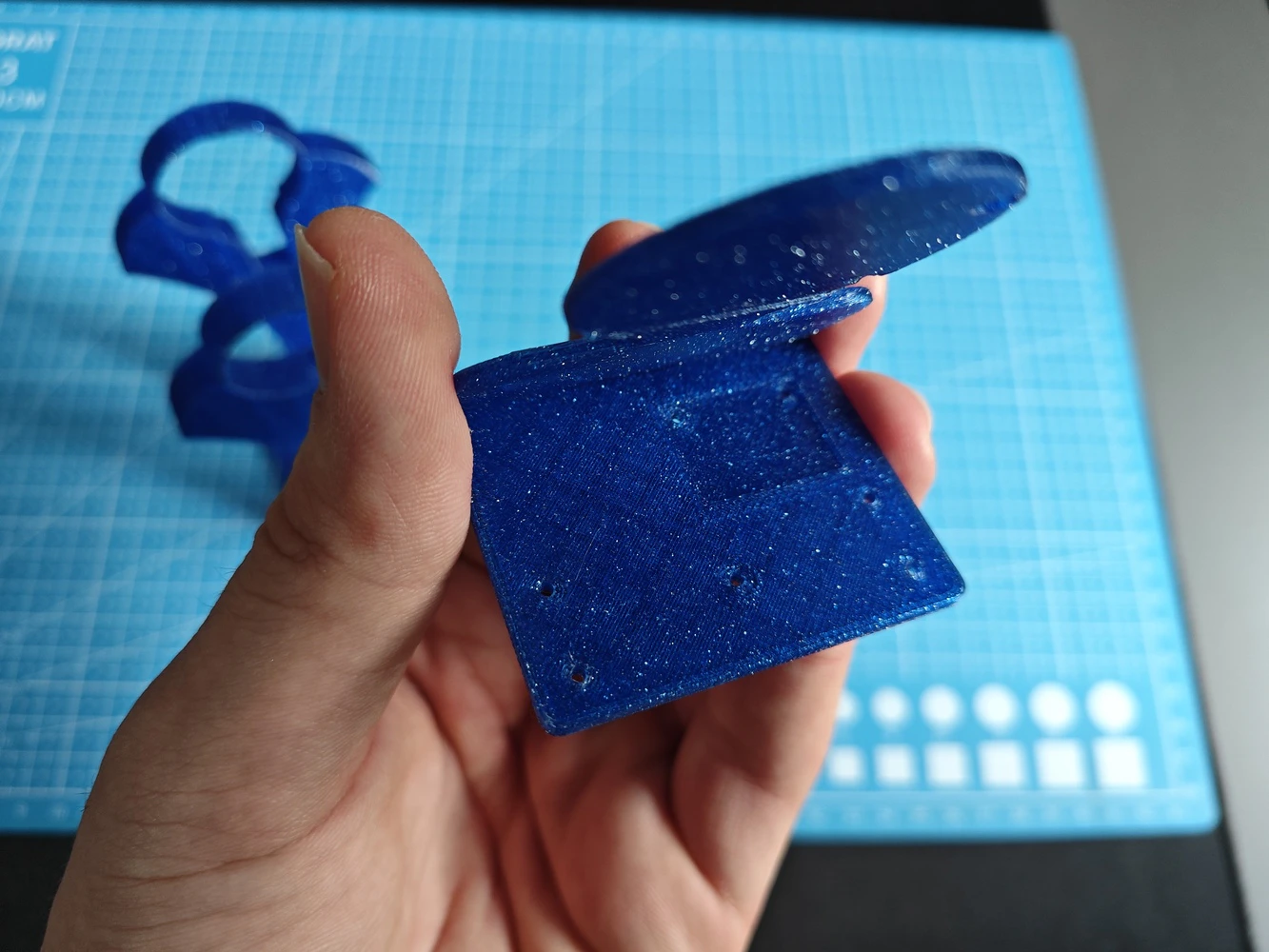
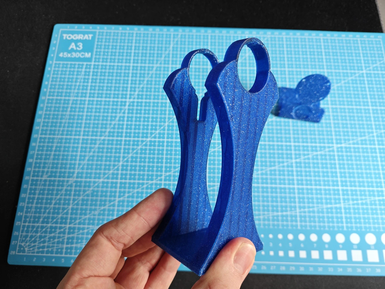
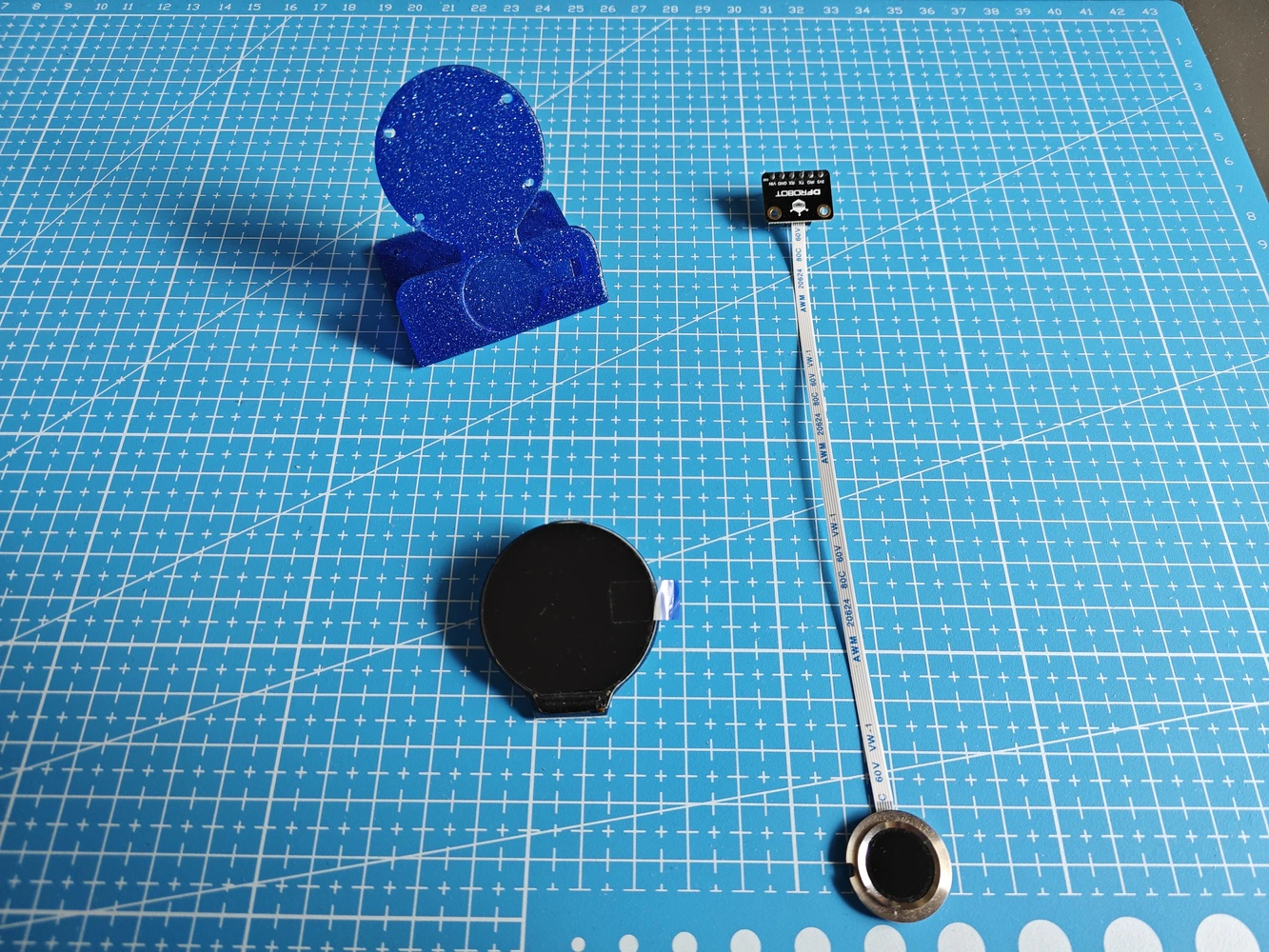
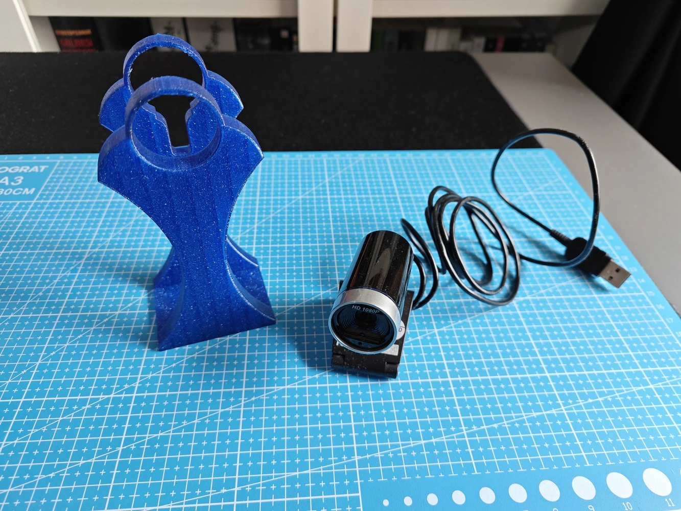
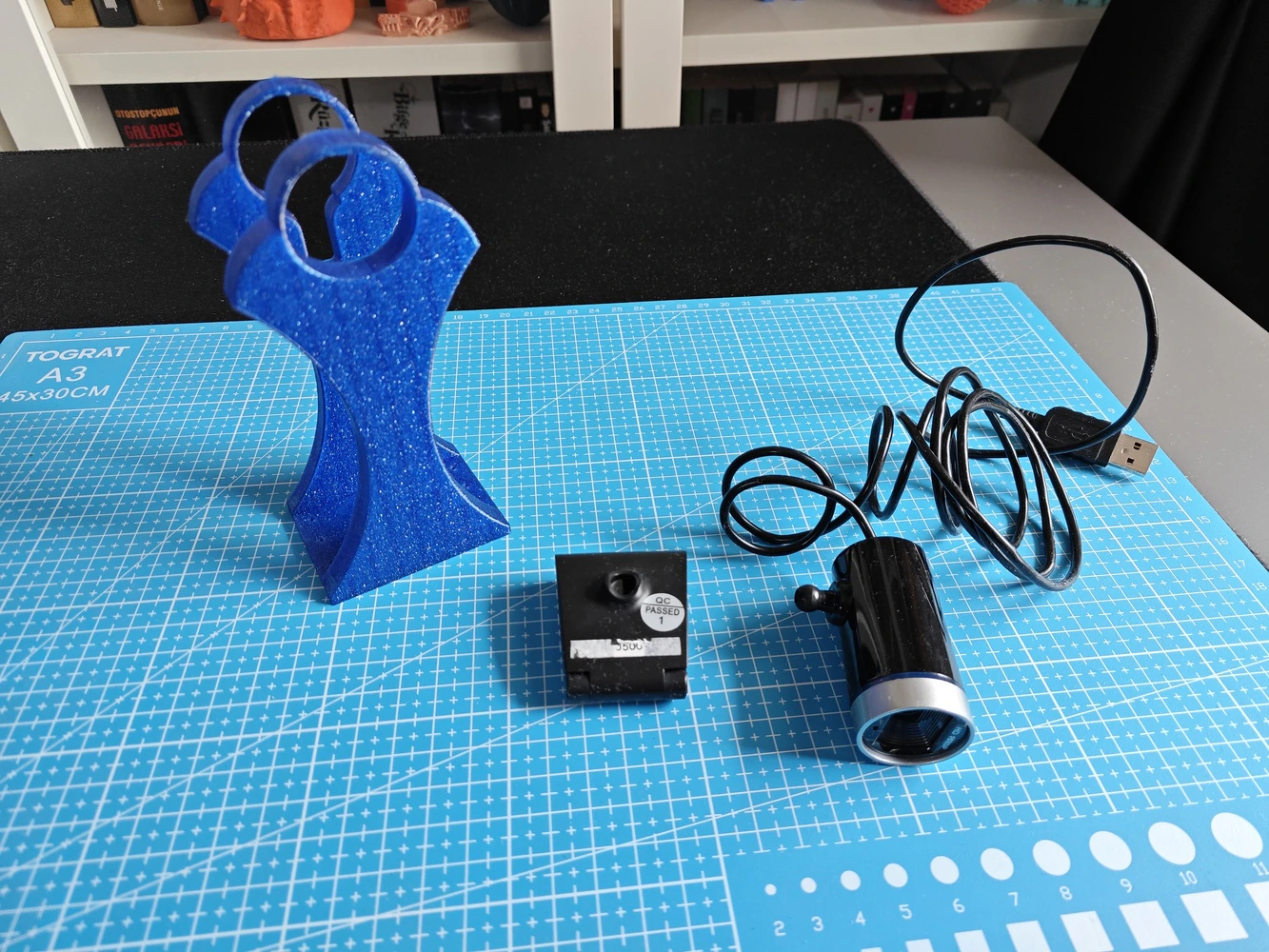
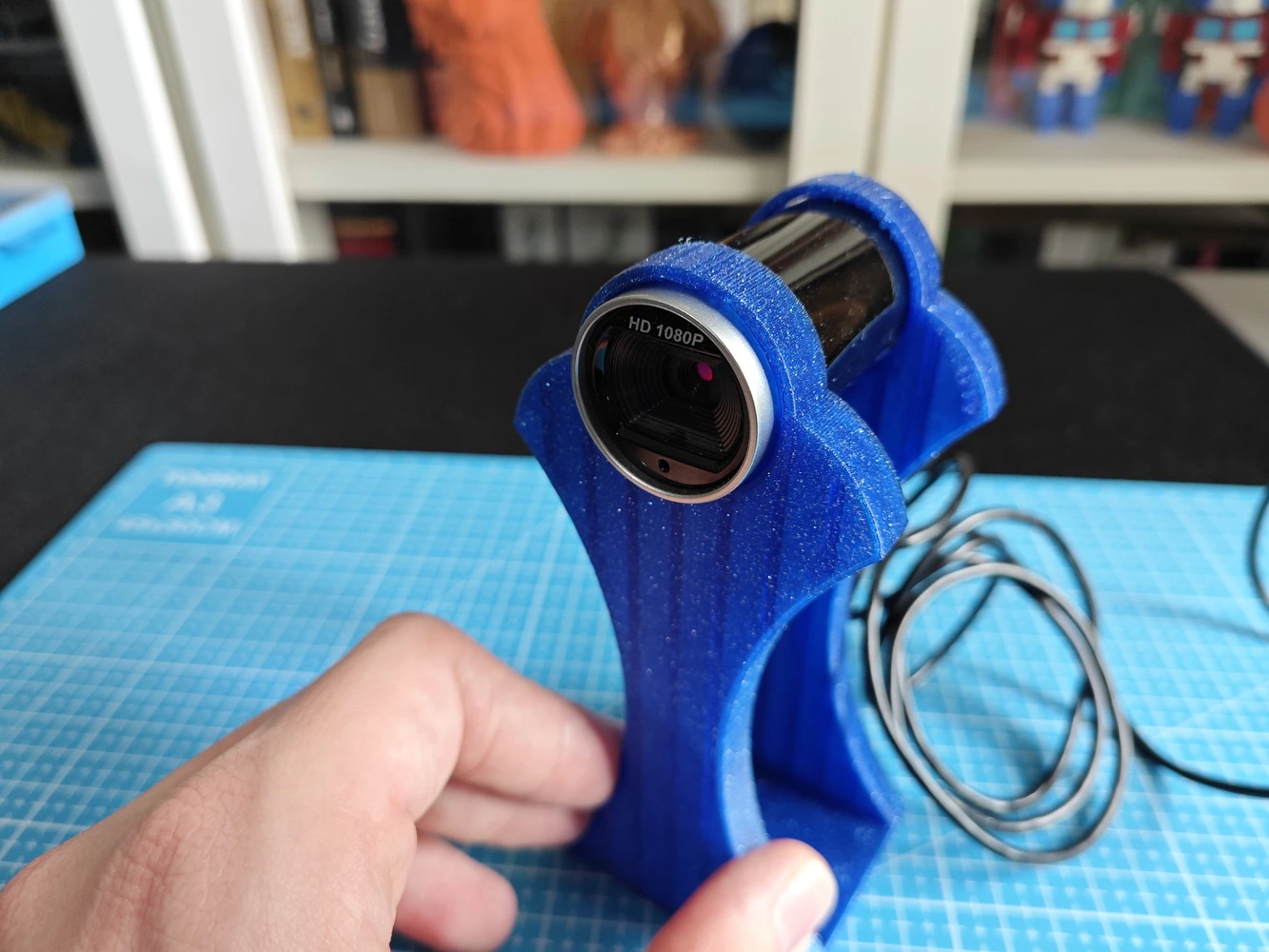
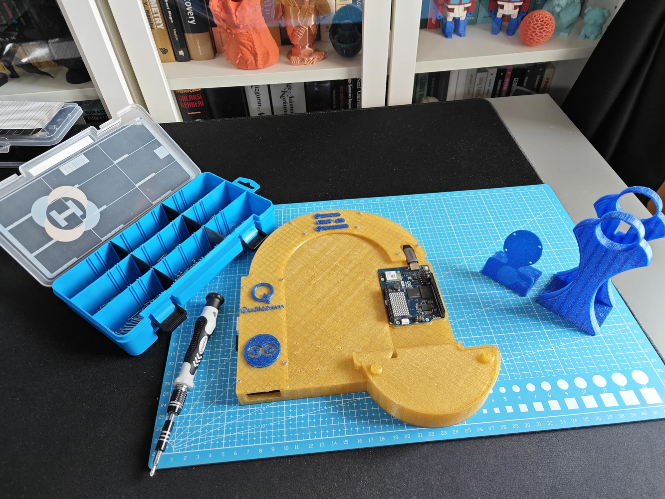
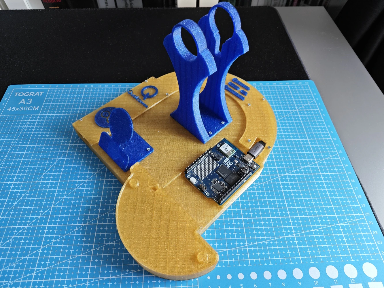
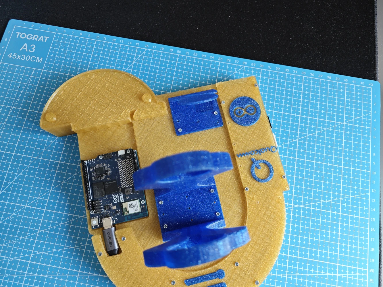
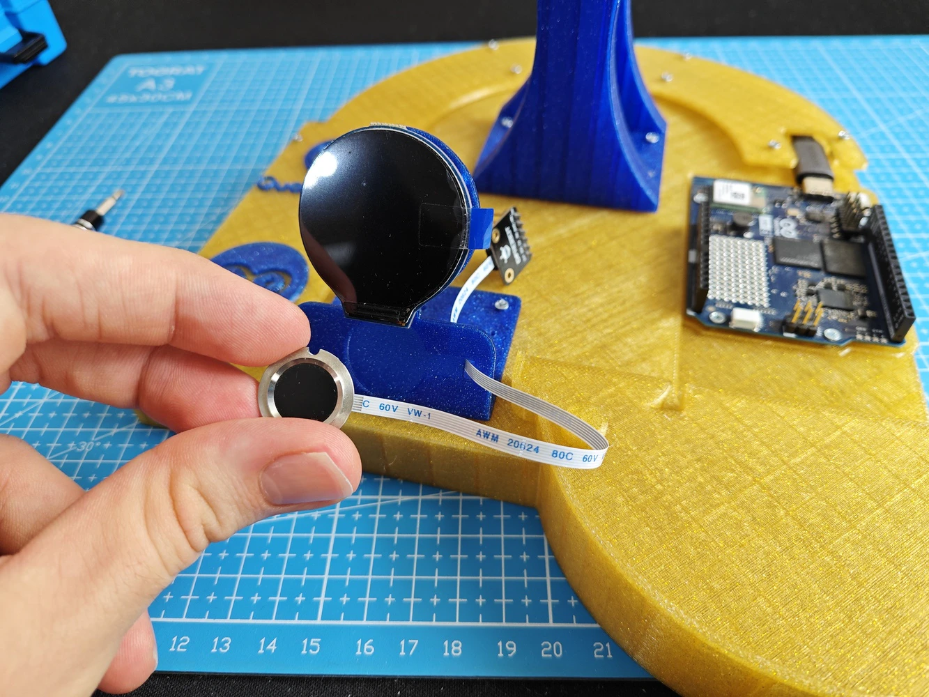
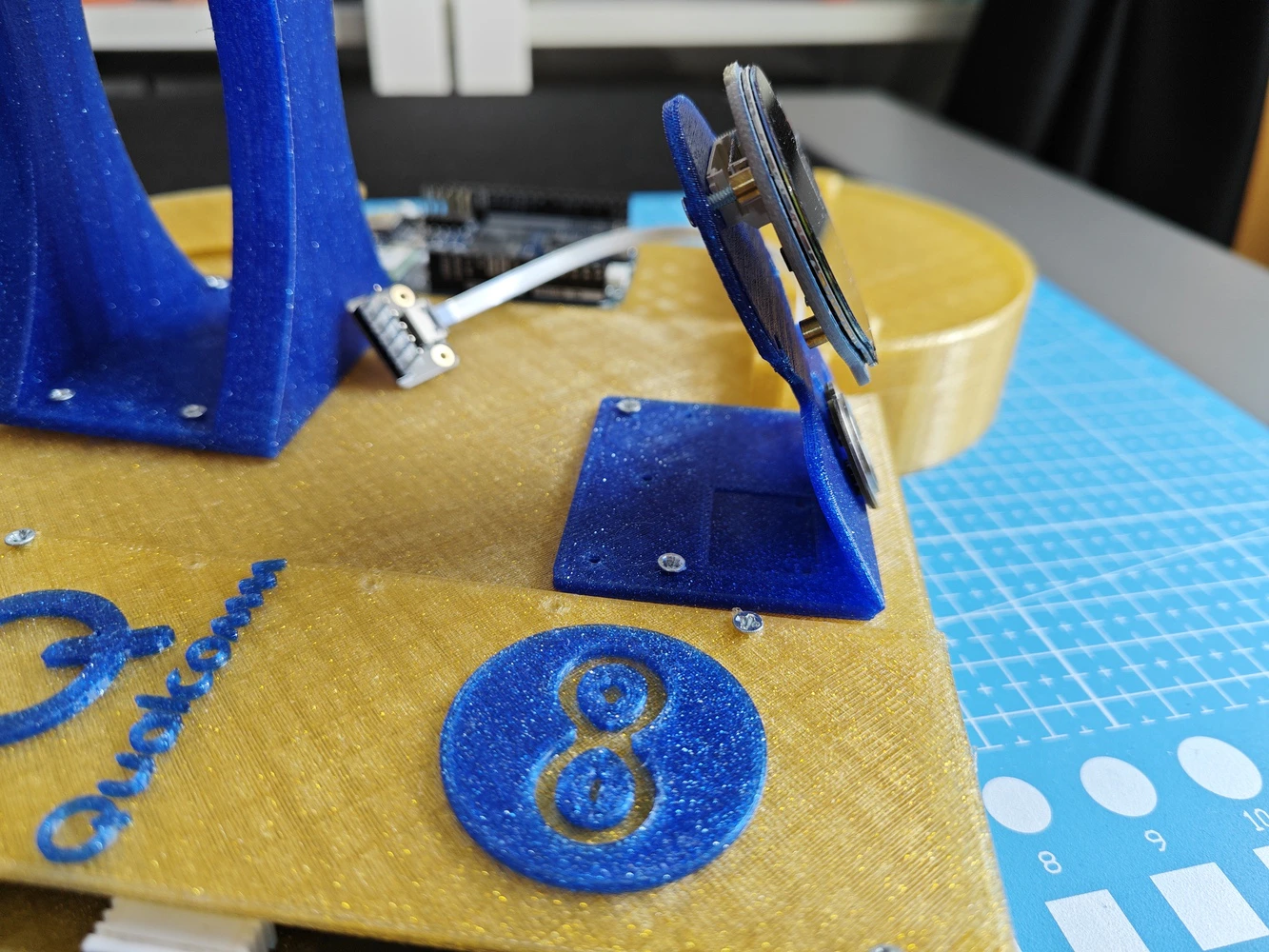
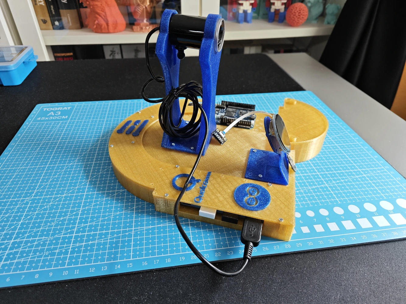
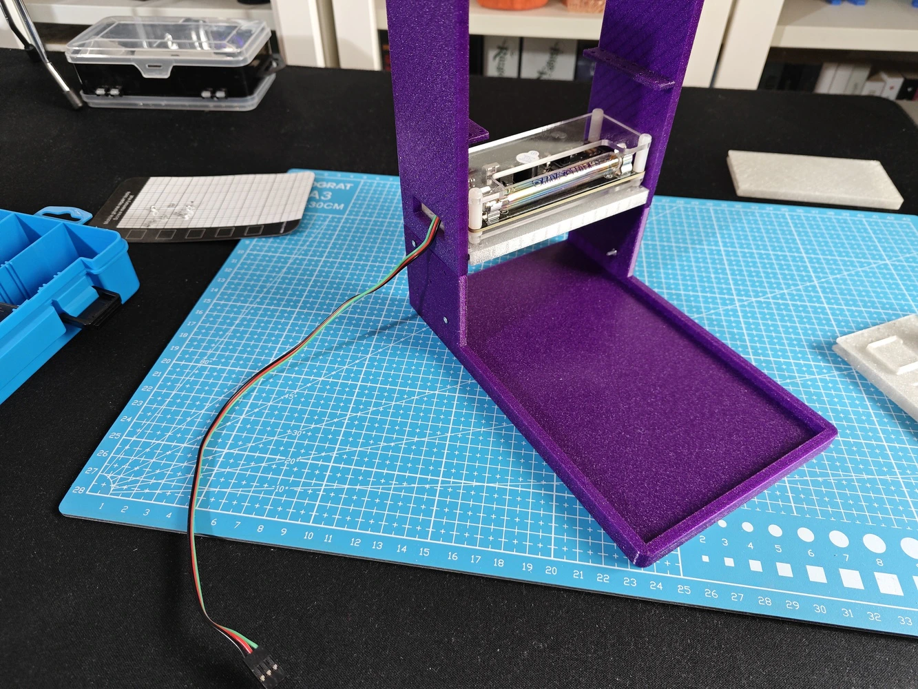
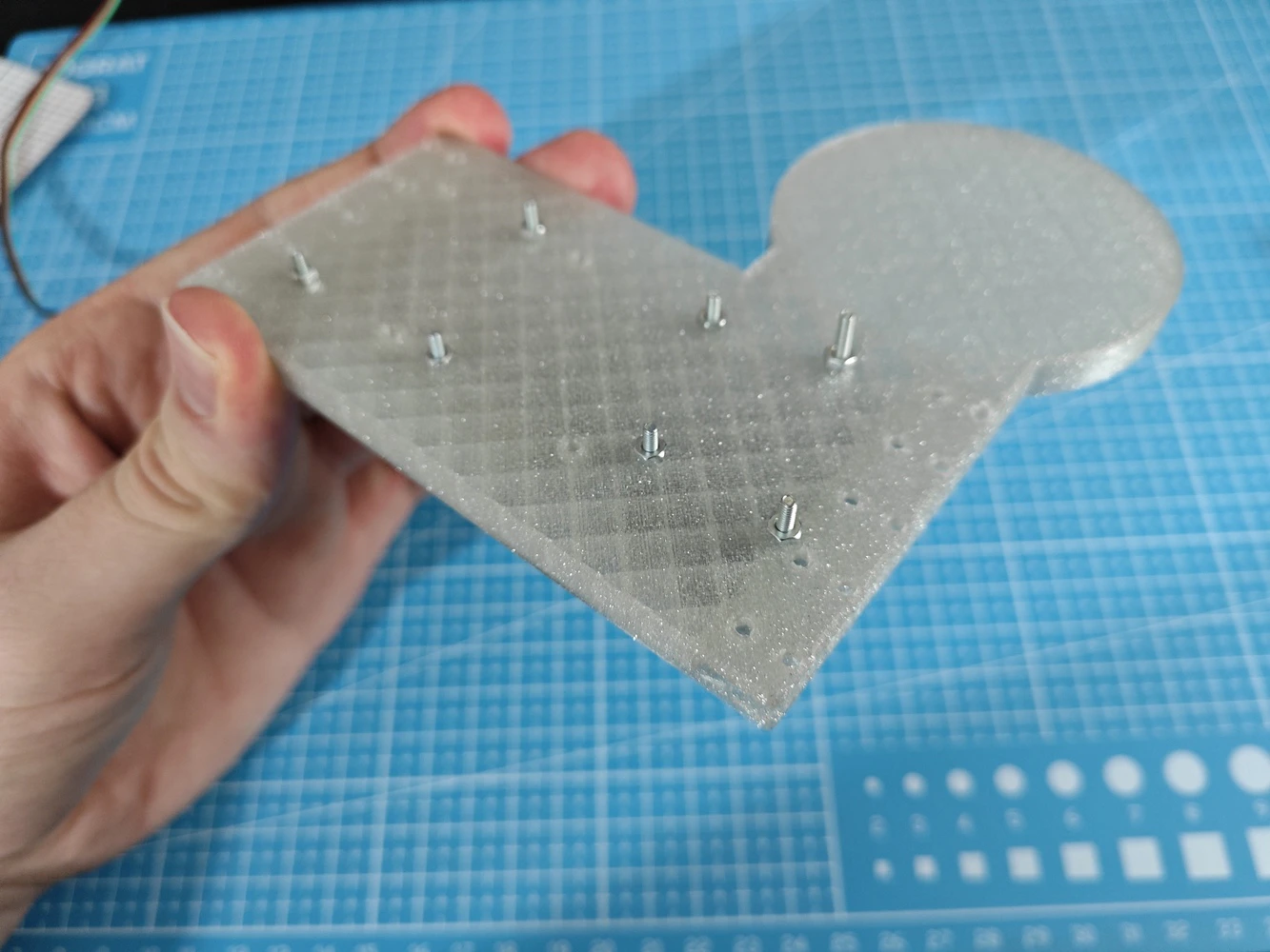
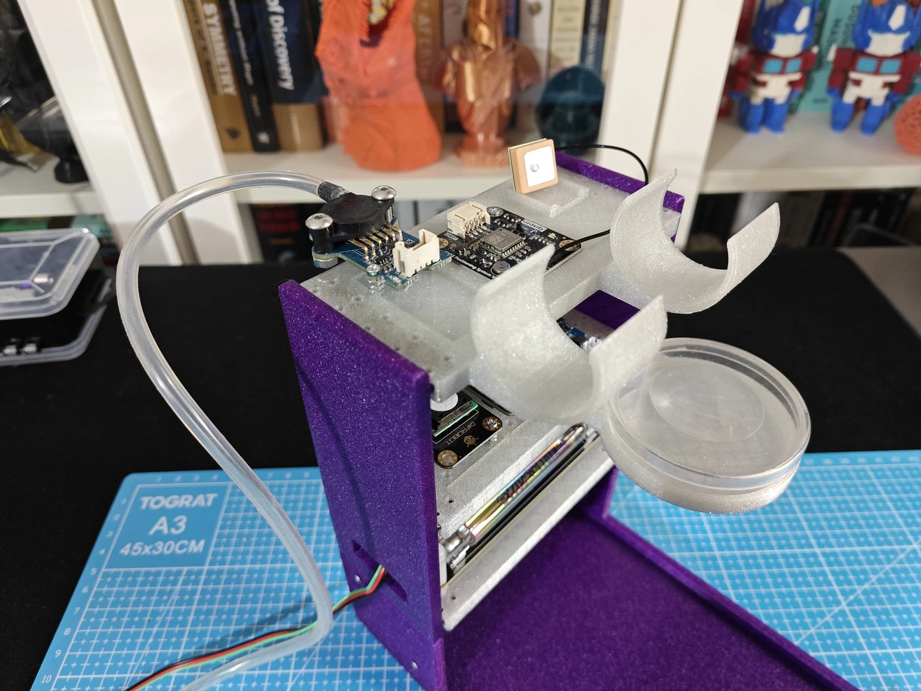
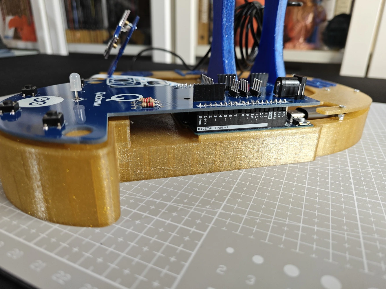
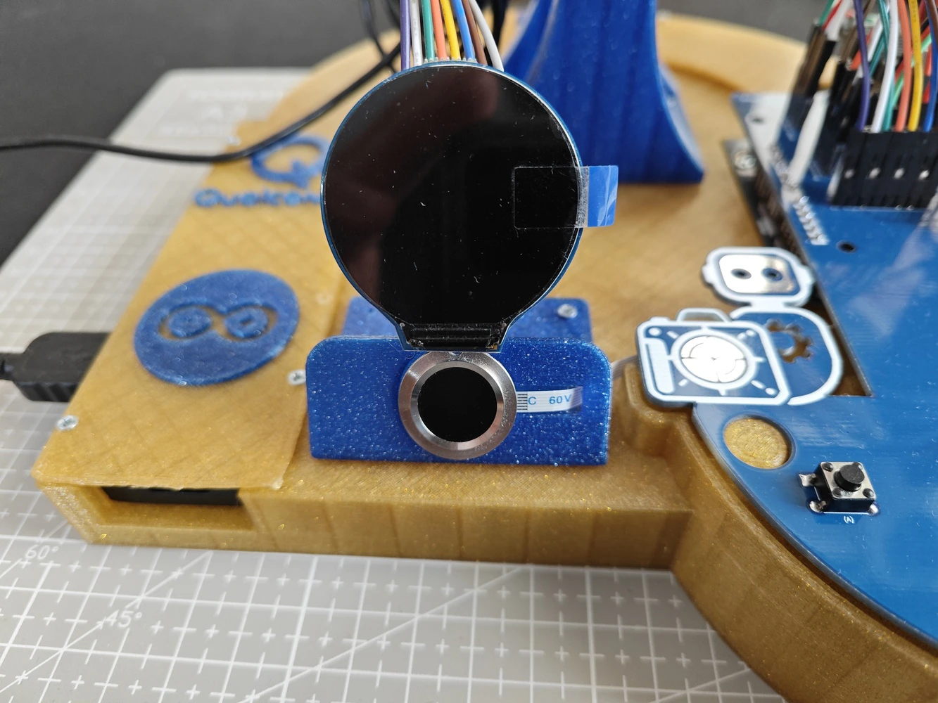
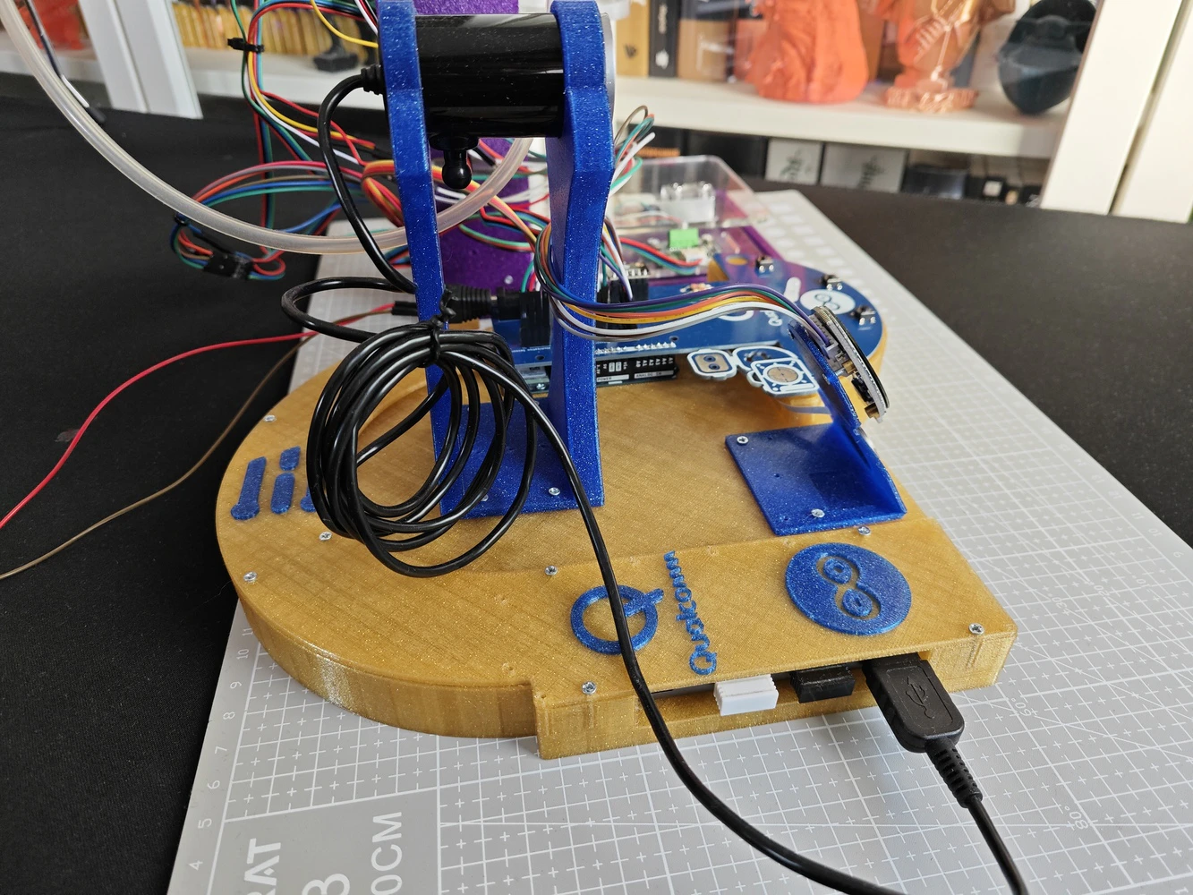
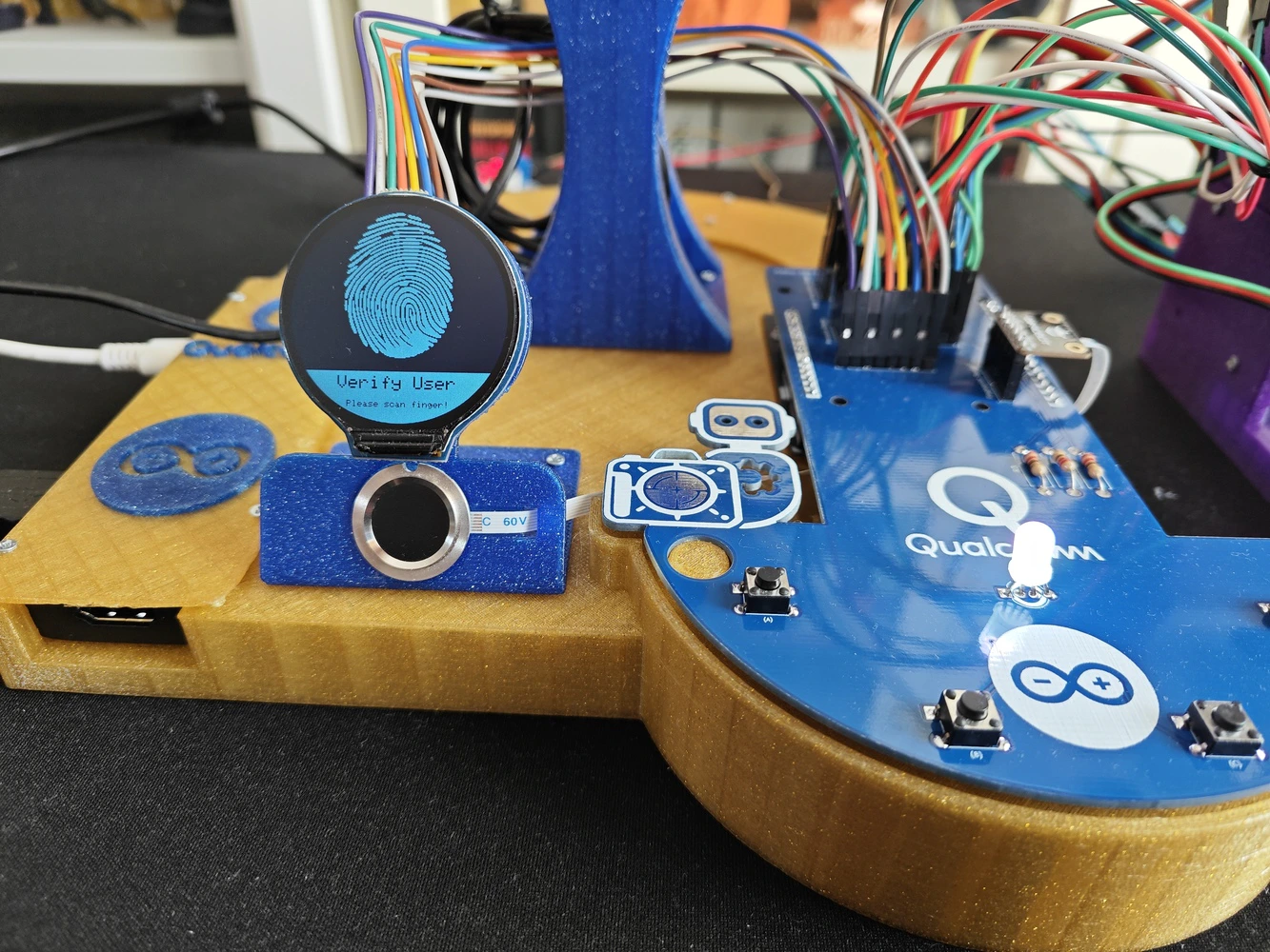
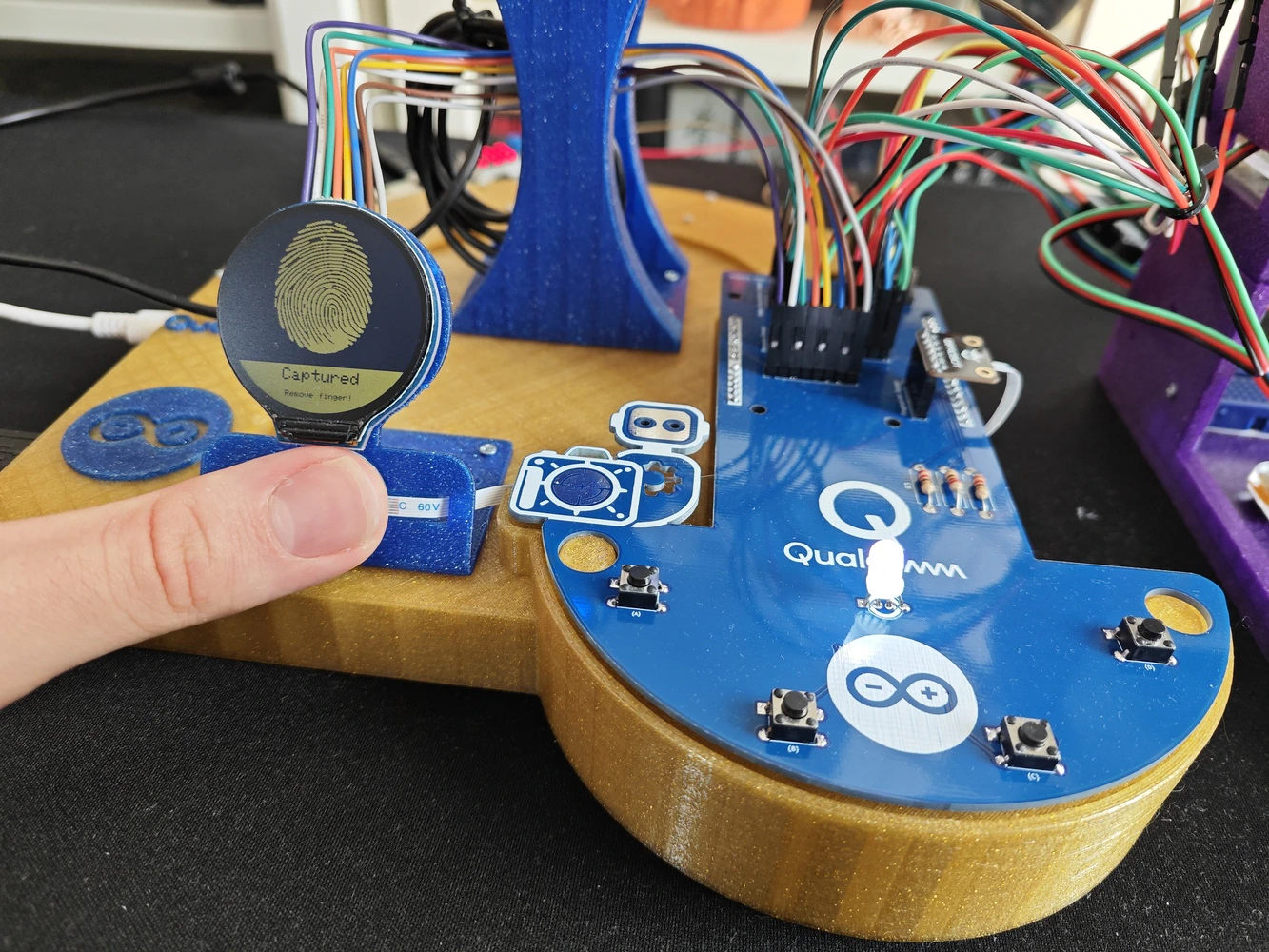
#️⃣ First, I designed the lab assistant base, which embeds the Arduino UNO Q and the UGREEN 5-in-1 USB hub (dongle). #️⃣ I added two pegs to easily place the analog interface PCB via its guiding features and ensured the PCB outline has enough clearance once attached onto the UNO Q as a shield. #️⃣ To secure the USB dongle and its USB-C cable connected to the UNO Q, I designed a specific USB hub cover. #️⃣ I designed the base to allow the user to access all USB hub ports (5-in-1), including HDMI, once the hub cover is installed. #️⃣ To build an intuitive analog interface, I designed a unique round display and capacitive fingerprint sensor mount. #️⃣ I also designed a unique USB camera stand compatible with the A4 Tech PK-910H USB webcam. I estimated the camera stand height by considering the camera FOV (Field of View) to avoid capturing the obstructing front base section. #️⃣ All component connections, including the Arduino UNO Q, are established via self-tapping (secure fit) M2 holes.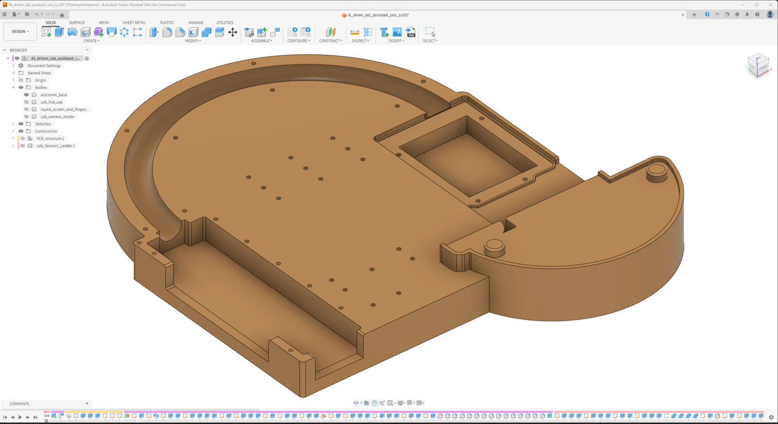
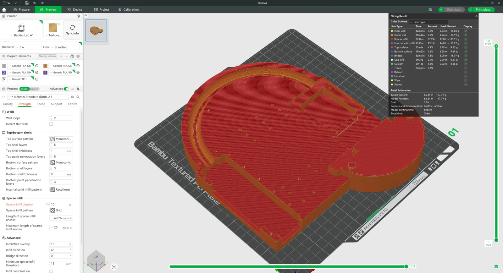
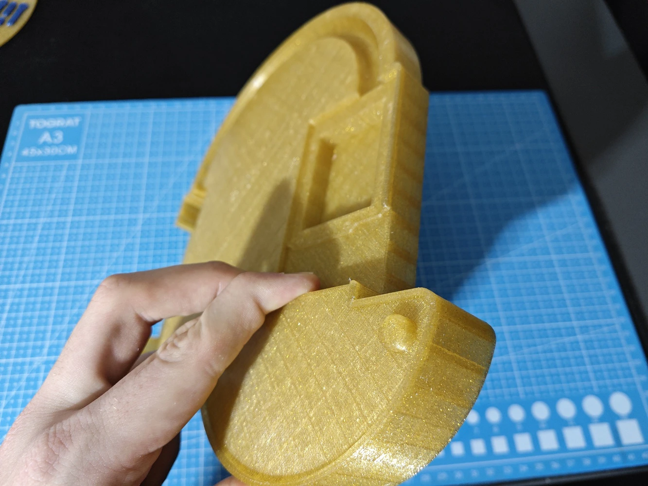
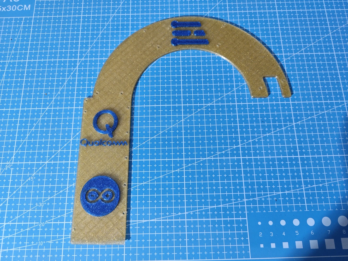
Step 9.a.1: Printing and assembling the assistant base
#️⃣ I sliced the assistant base with 10% sparse infill density instead of the default 15%. #️⃣ To highlight the brand logos on the USB hub cover, I applied the built-in Bambu Studio painting tool. #️⃣ To strengthen the round display mount, I set its wall loop (perimeter) number to 3.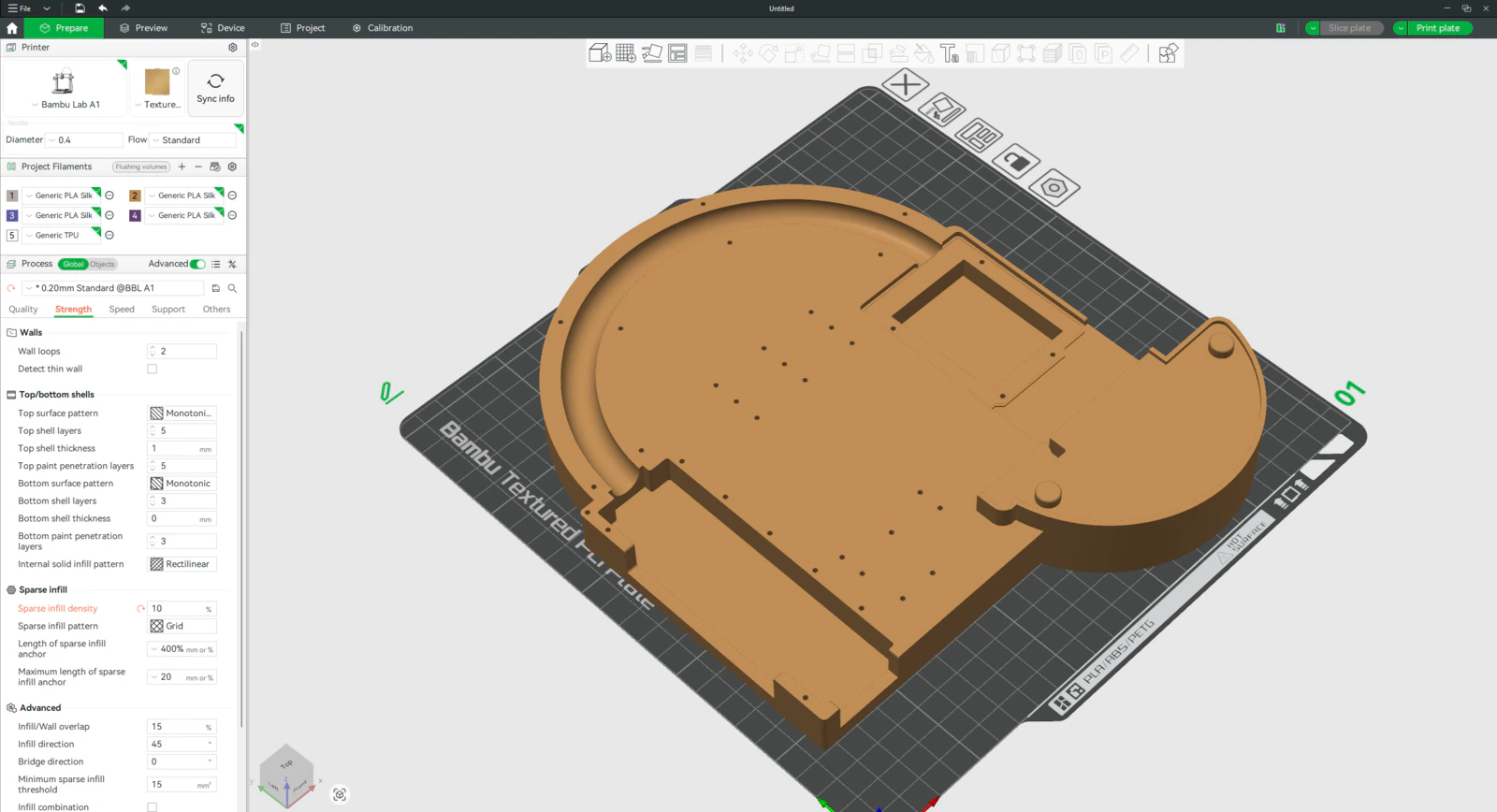

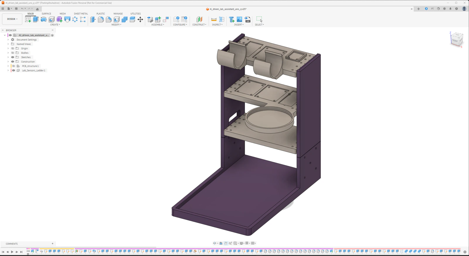
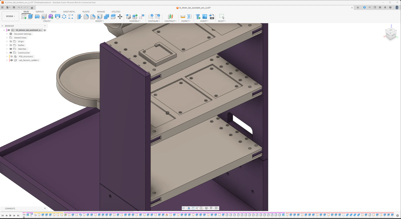
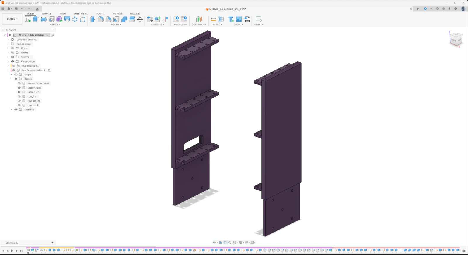
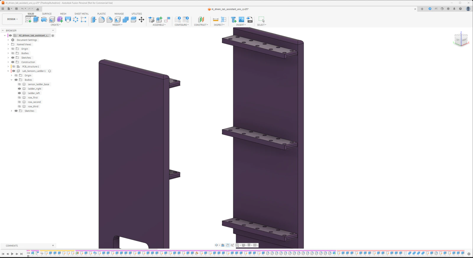
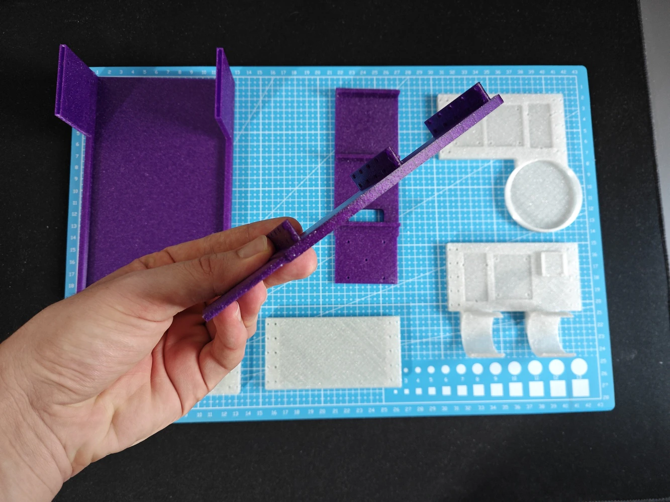
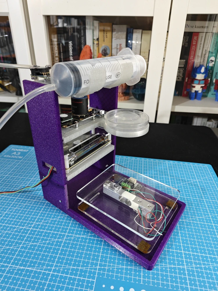
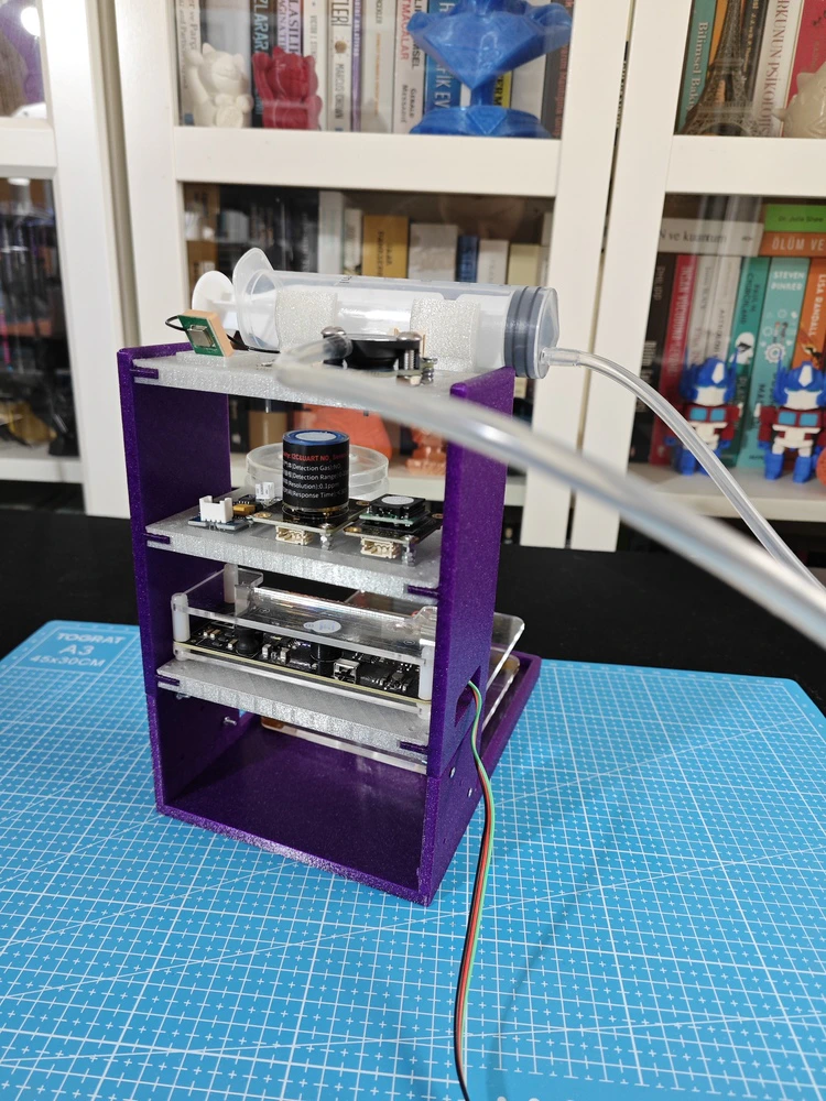
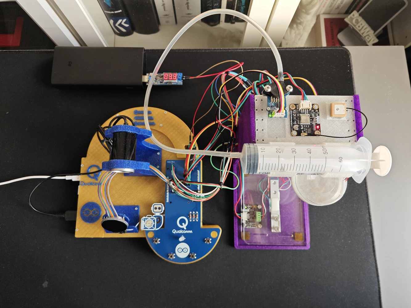
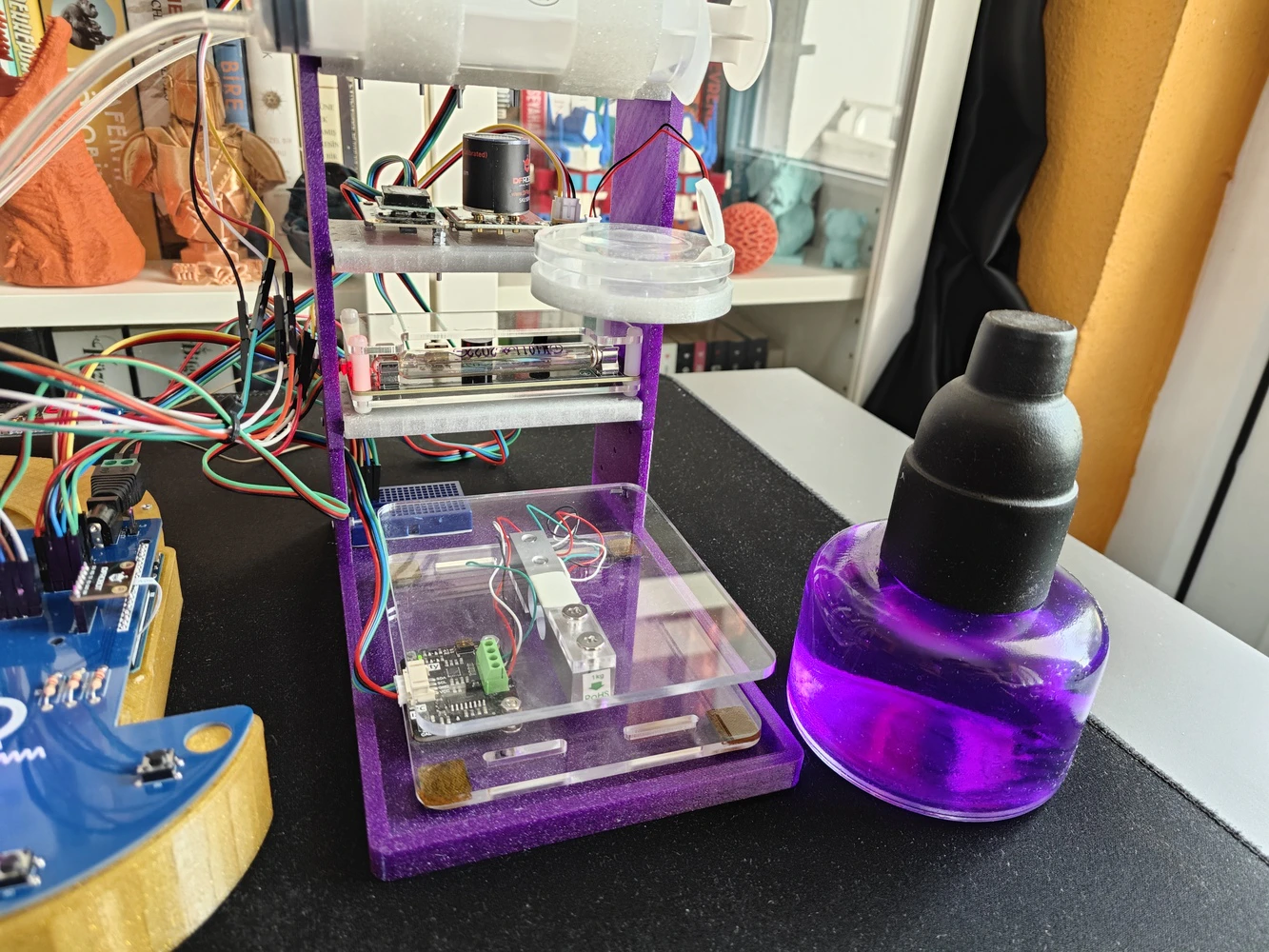
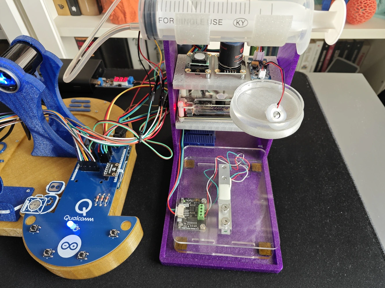
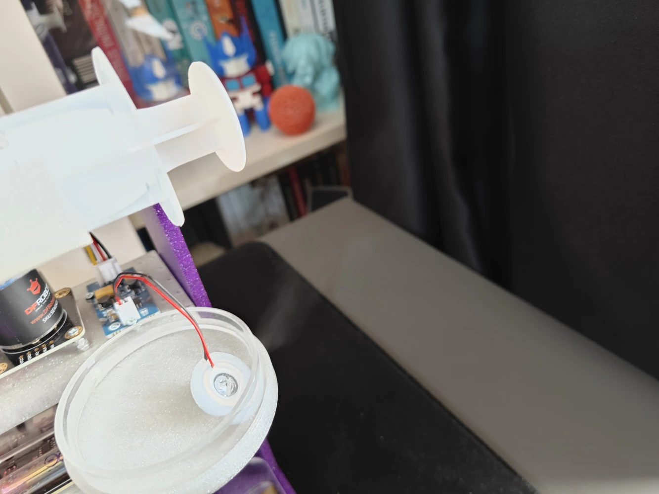
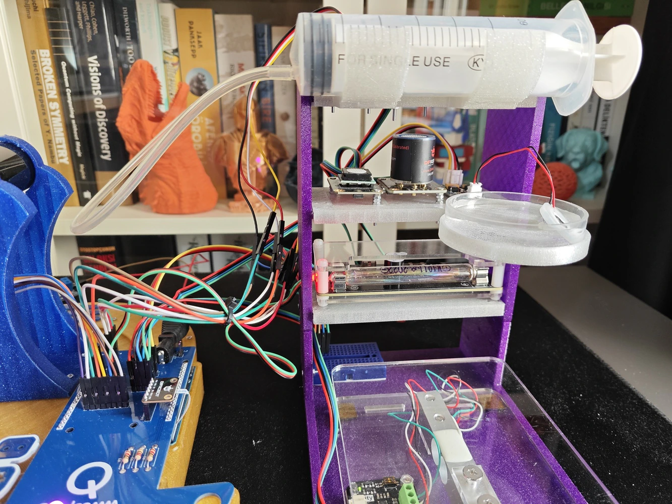
Step 9.b: Designing the experiment-ready modular lab assistant sensor ladder
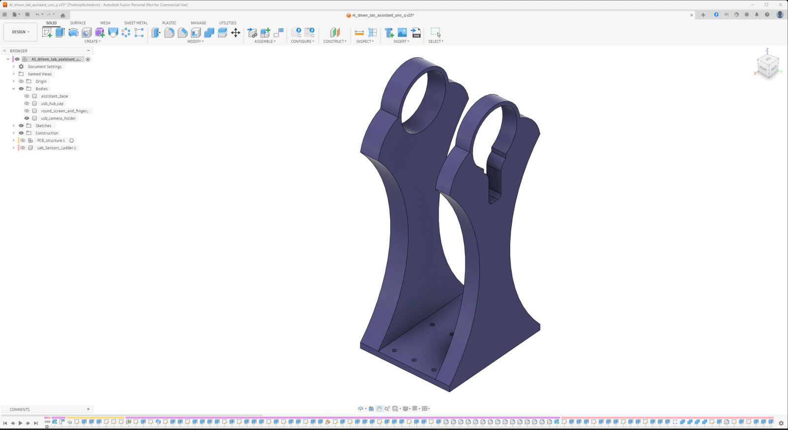
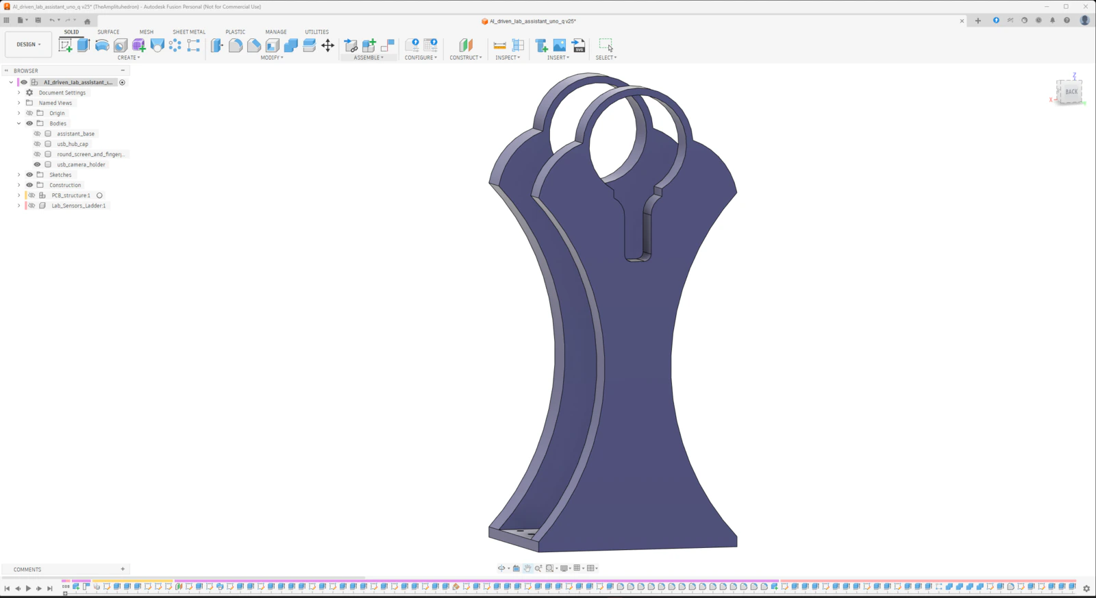
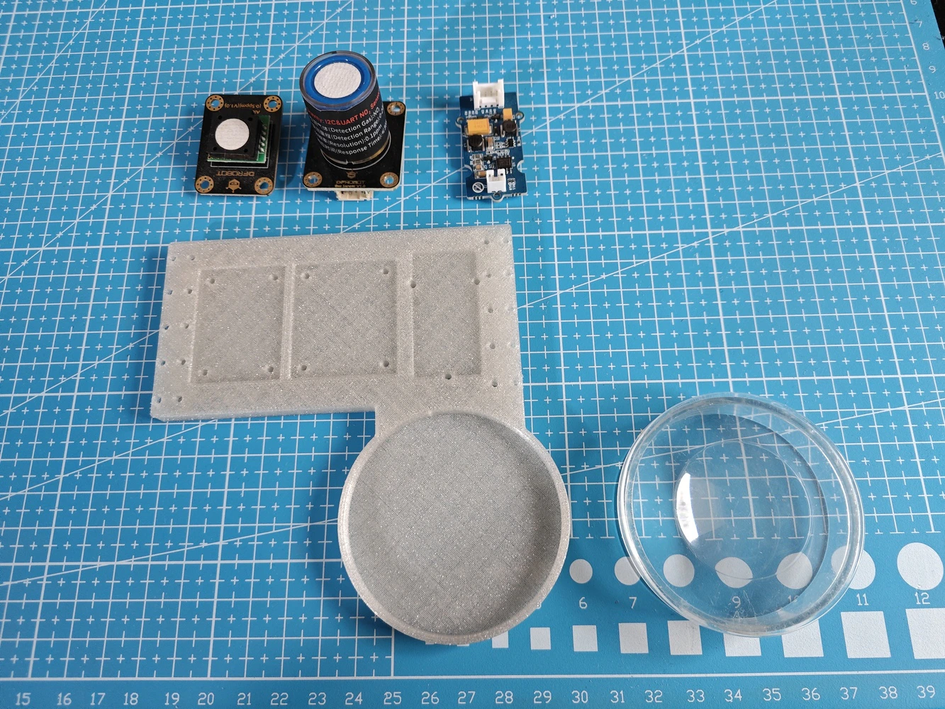
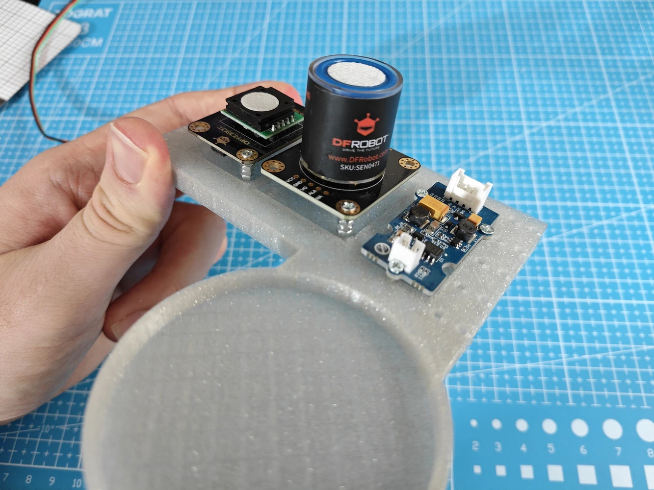
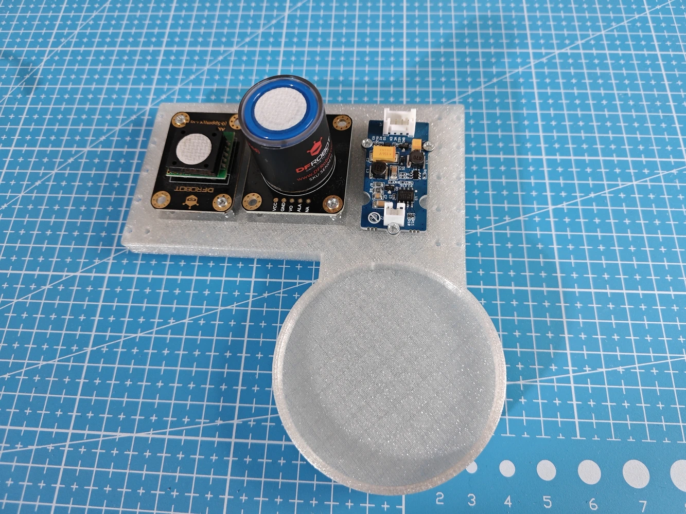
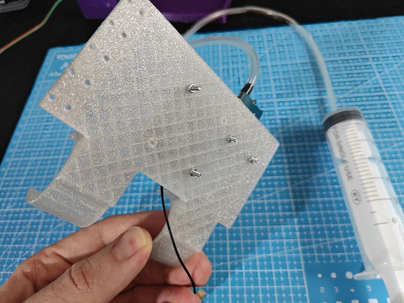
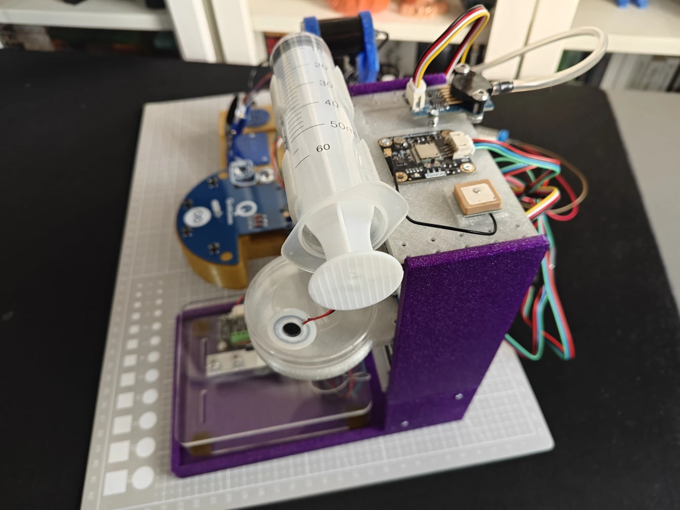
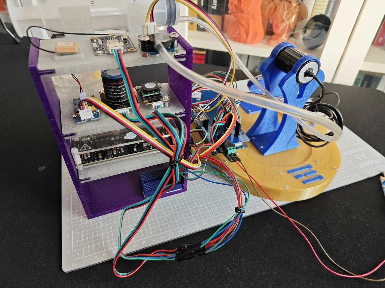
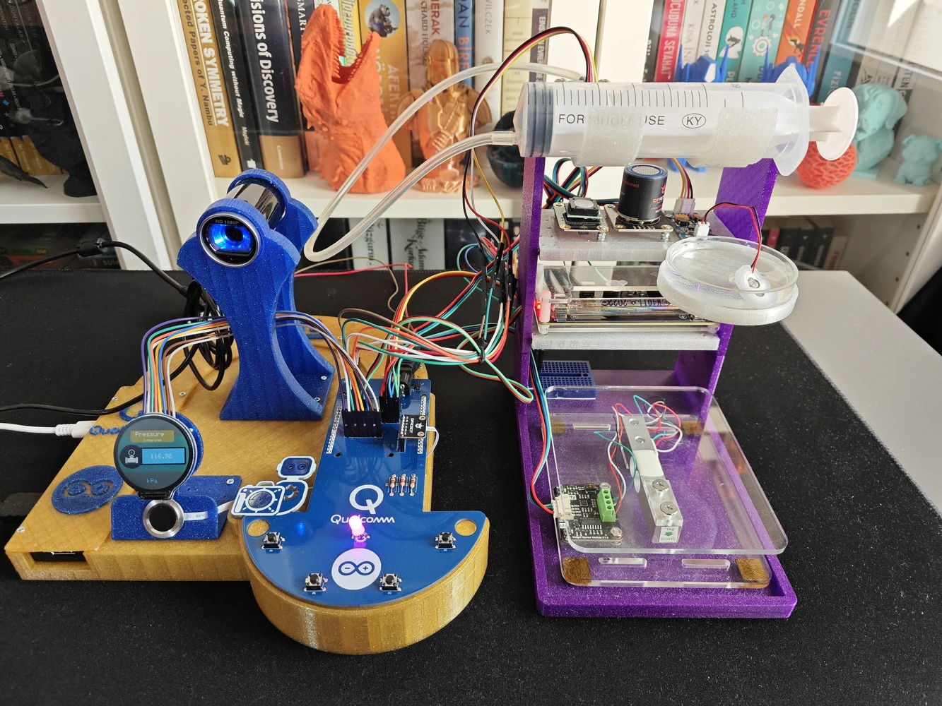
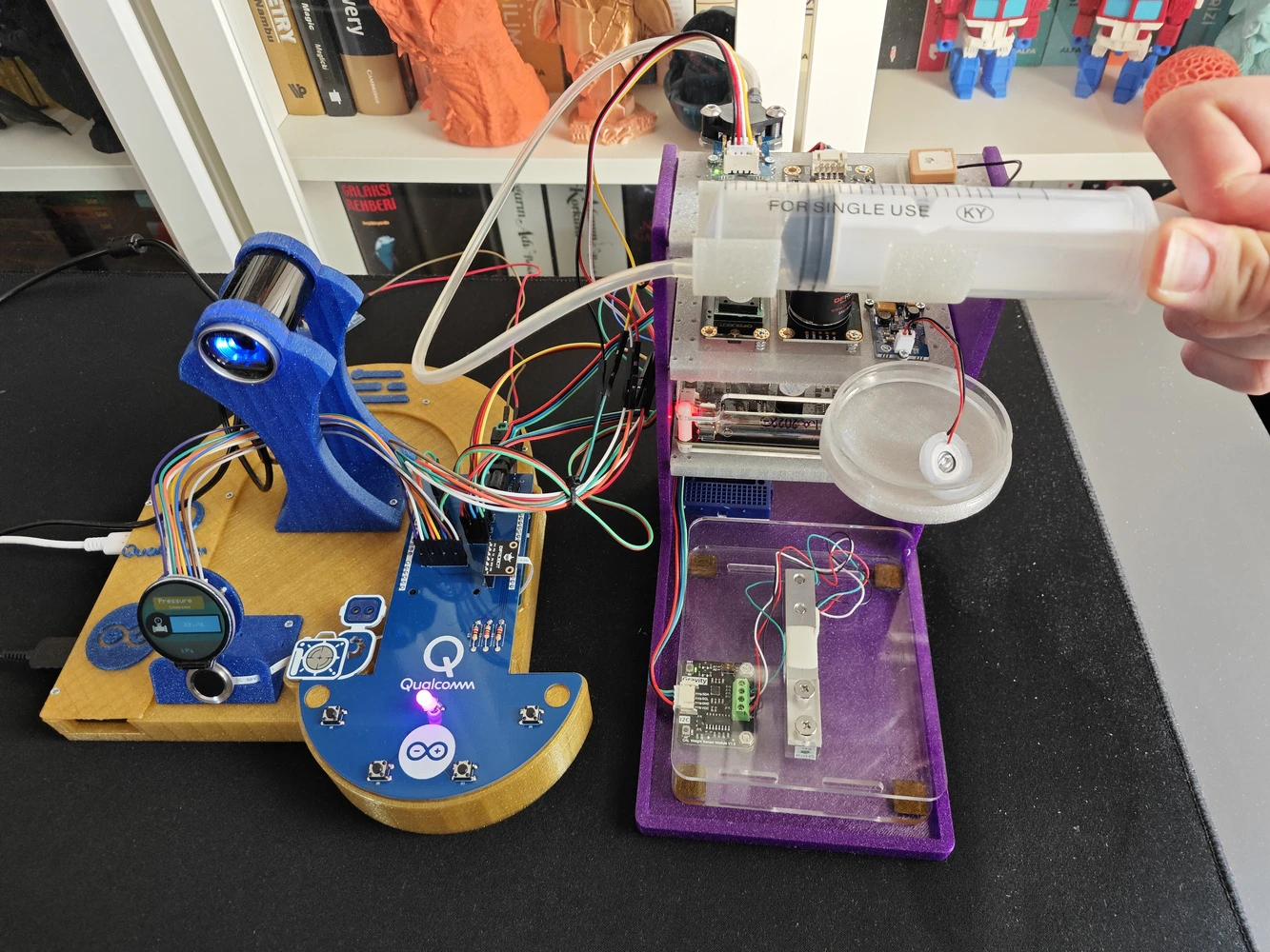
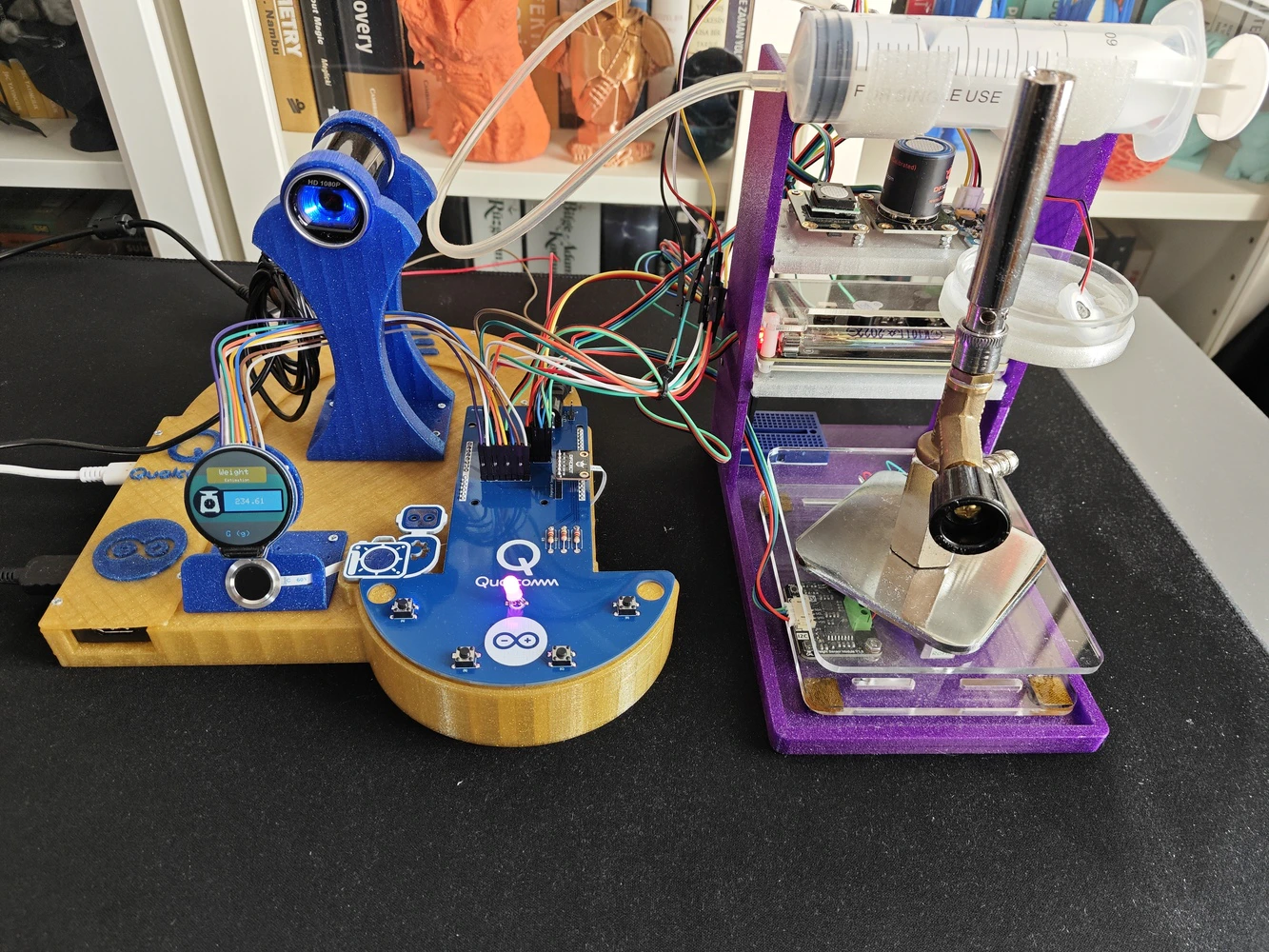
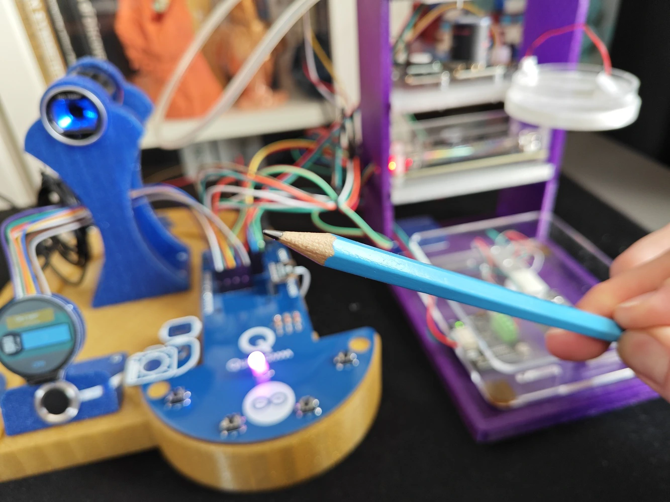
#️⃣ To allow users to conduct experiments with the implemented lab sensors and their associated tools intuitively, I designed this modular lab sensor ladder containing all of the lab sensors and secondary tools at its four levels. #️⃣ Each horizontal row (rung) of the sensor ladder includes dedicated slots and snap-fit joints for specific lab sensors and their secondary tools, such as the syringe for the pressure sensor.-
0️⃣Floor:
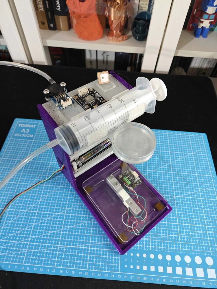
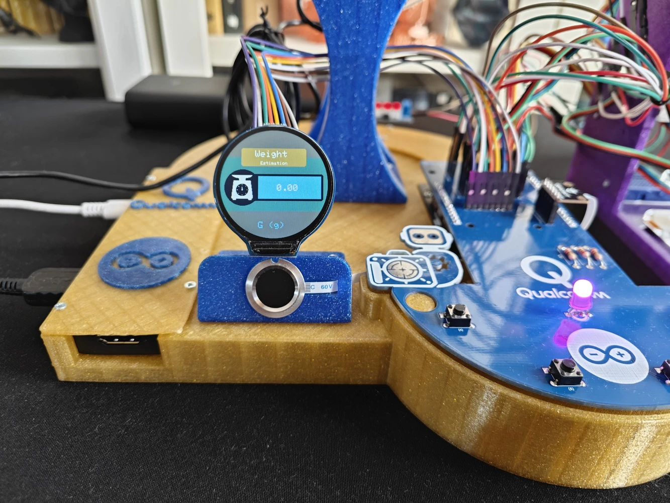
- Gravity: 1Kg Weight Sensor Kit - HX711
-
1️⃣ Rung (Row):
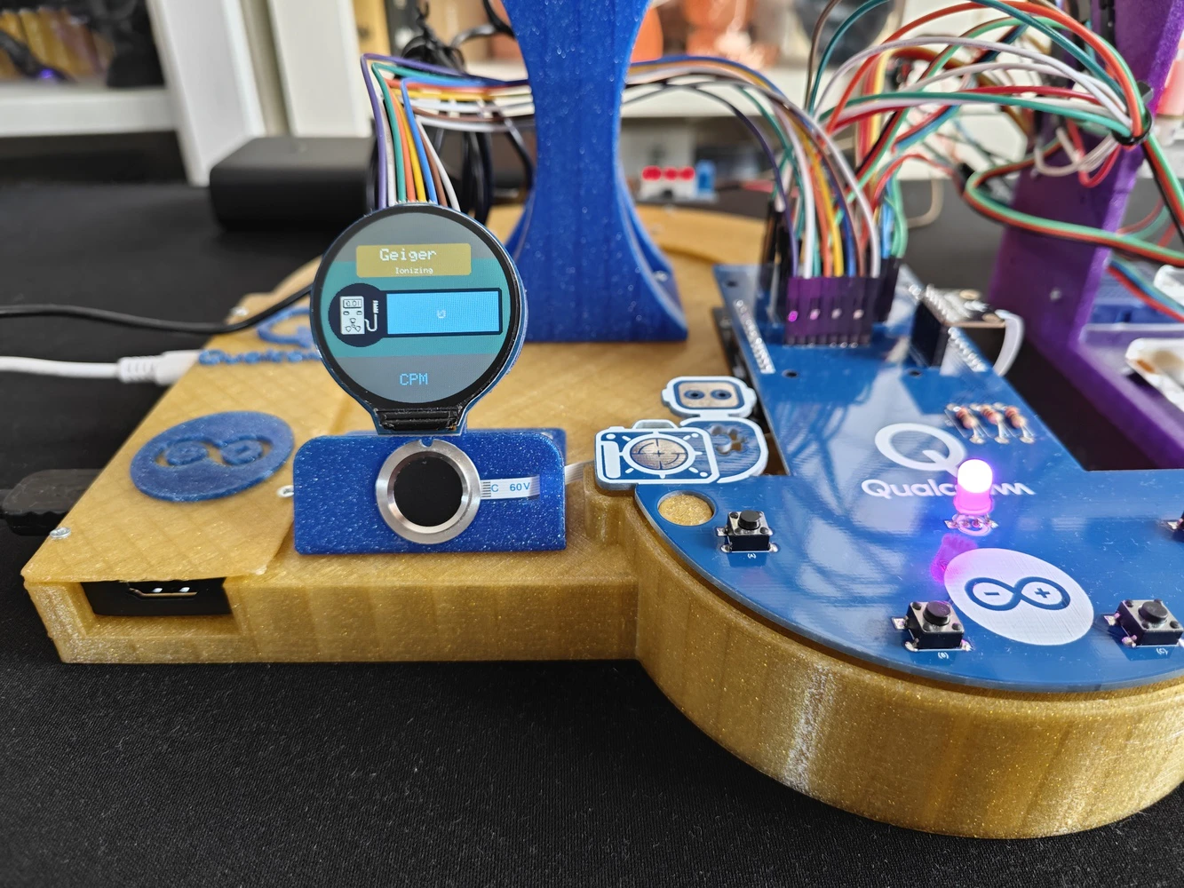
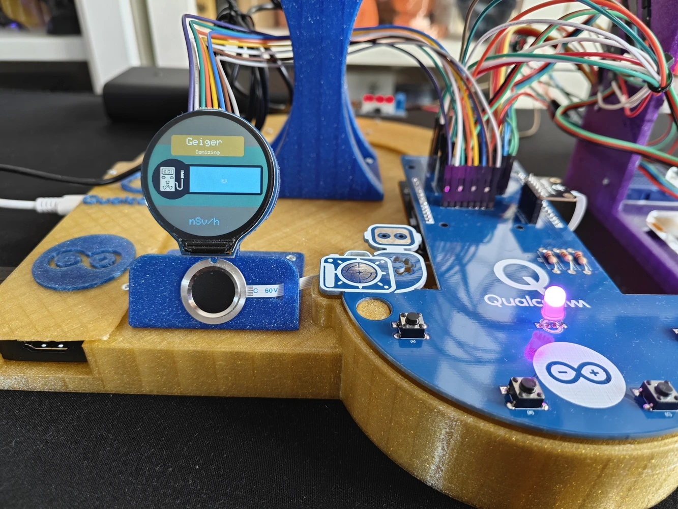
- Gravity: Geiger Counter Module - Ionizing Radiation Detector
-
2️⃣ Rung (Row):
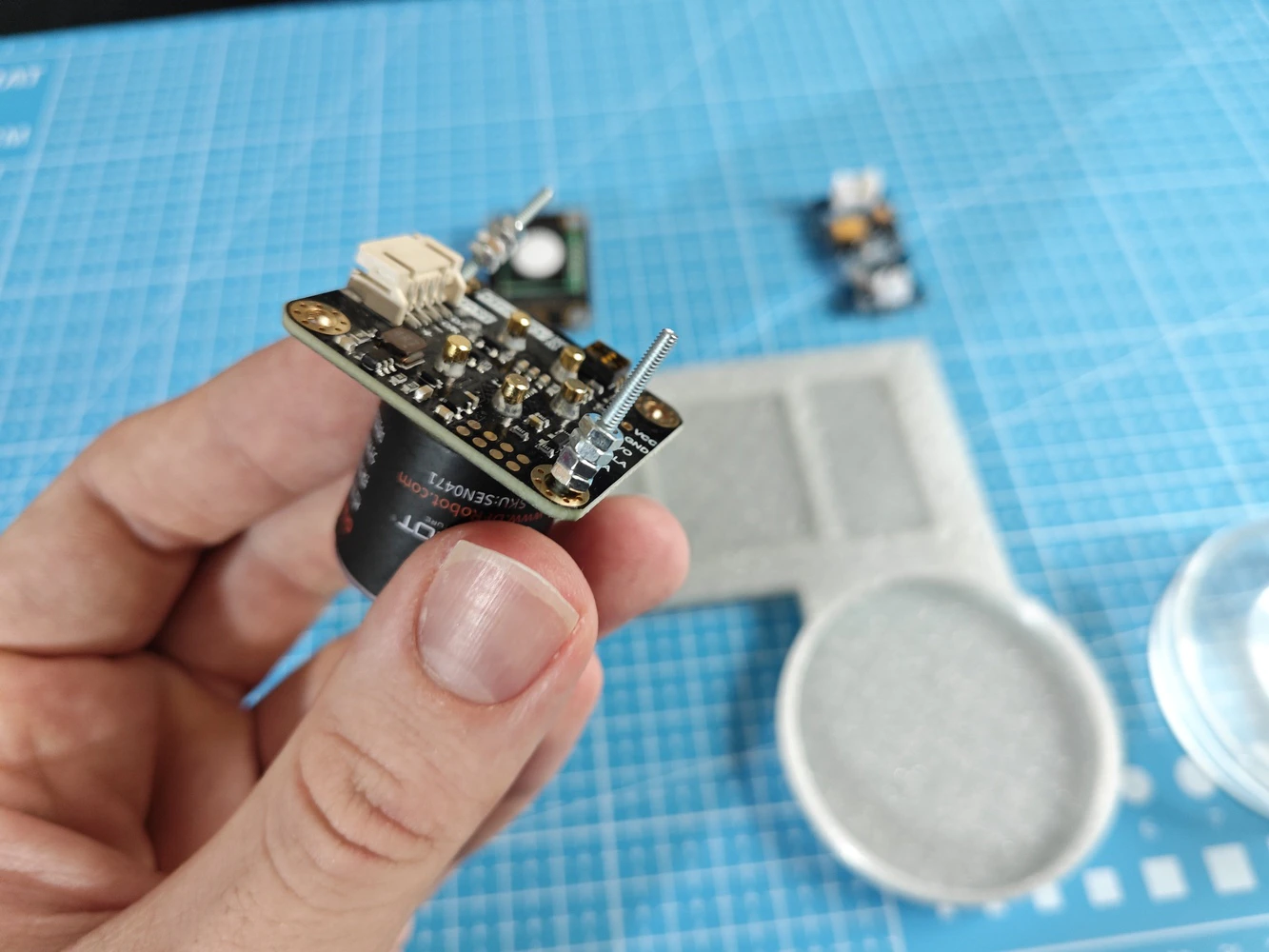
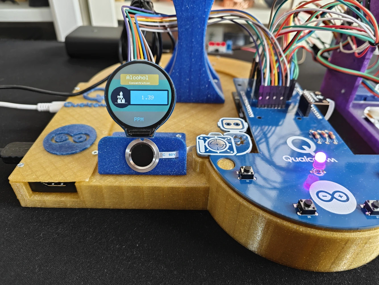
- Gravity: Electrochemical Alcohol Sensor
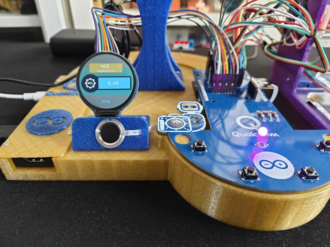
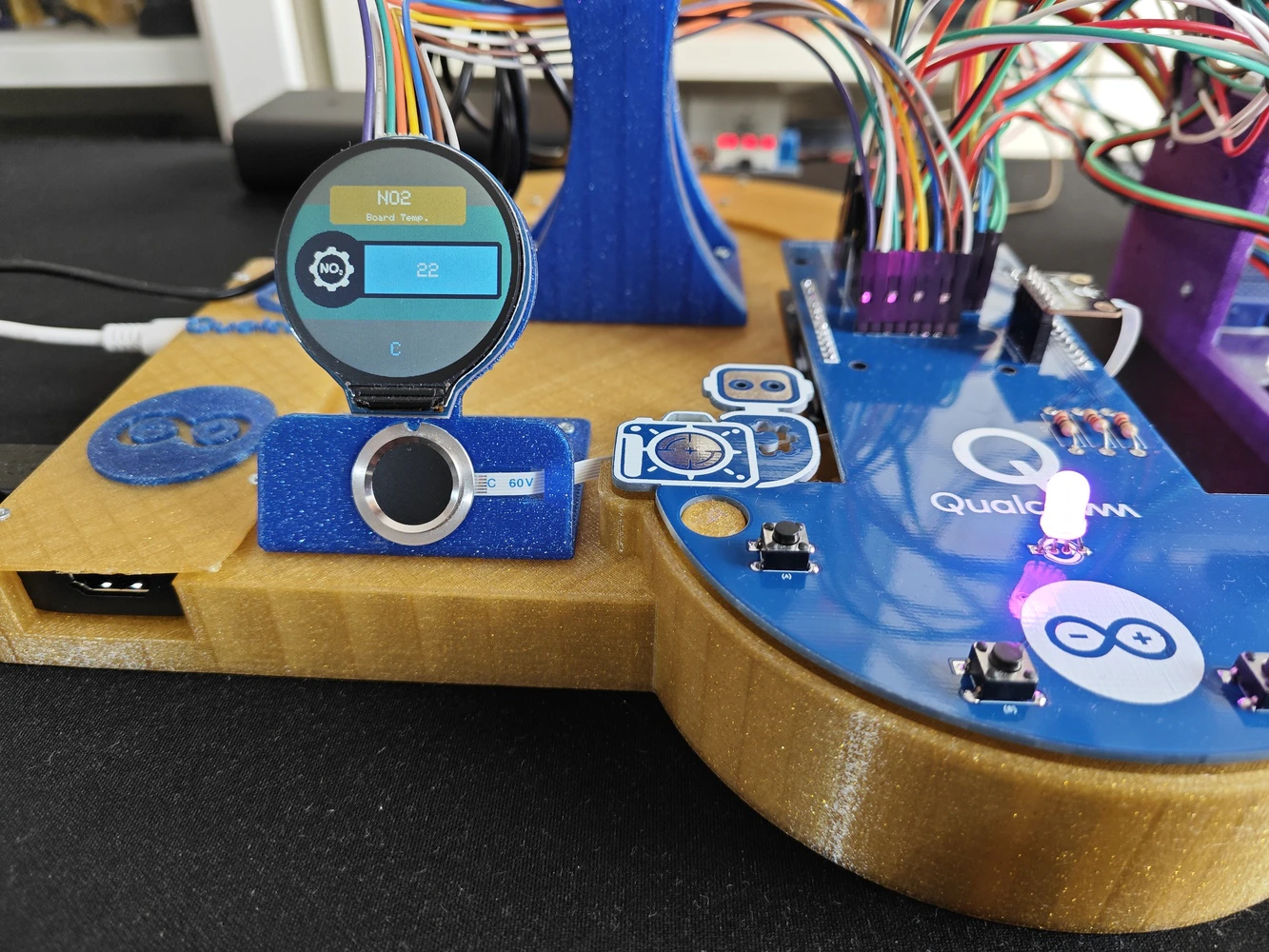
- Gravity: Electrochemical Nitrogen Dioxide Sensor - NO2
- Grove - Water Atomization Sensor - Ultrasonic
- 60 mm Petri Dish
-
3️⃣ Rung (Row):
- Gravity: GNSS Positioning Module
- Grove - Integrated Pressure Sensor Kit - MPX5700AP
- Syringe with rubber tube
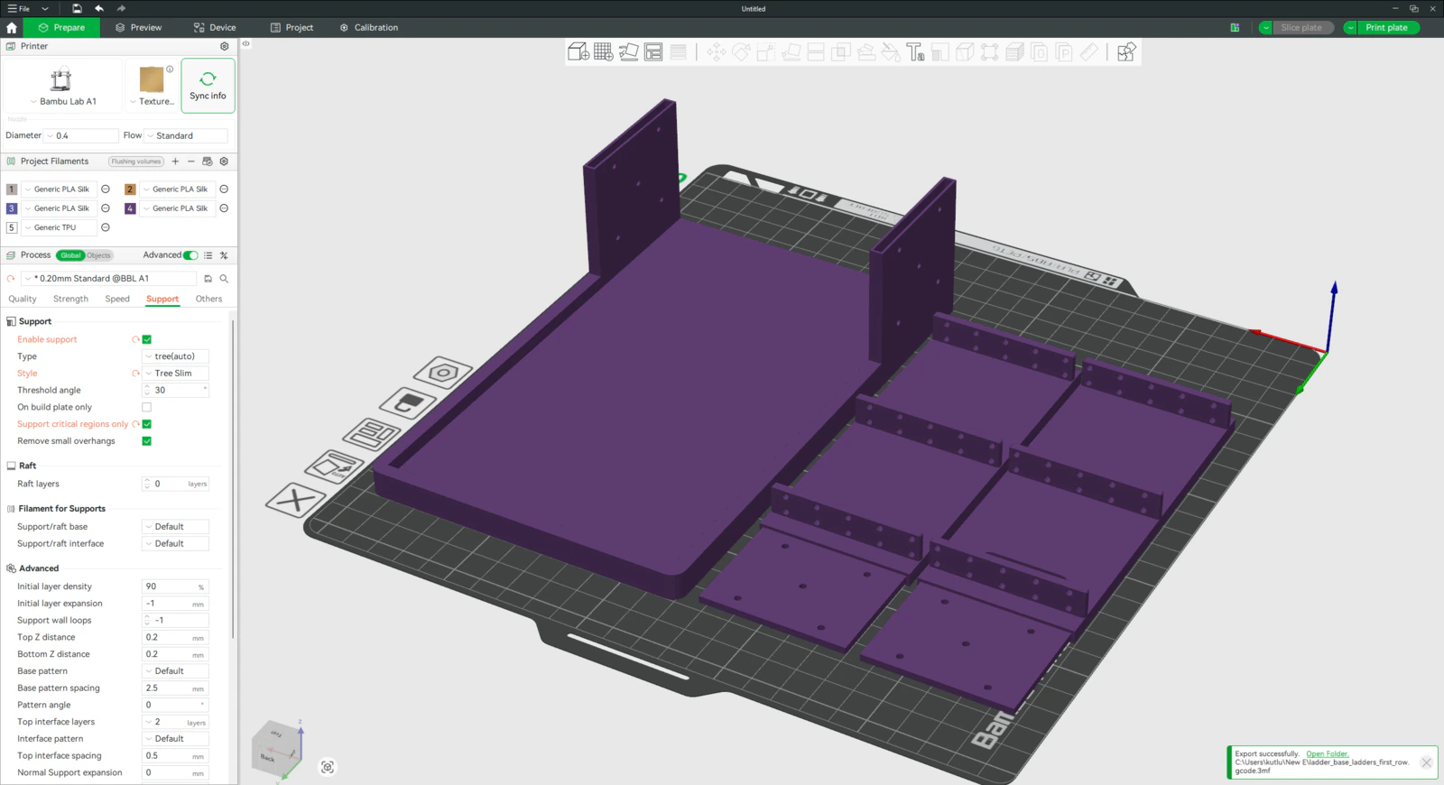
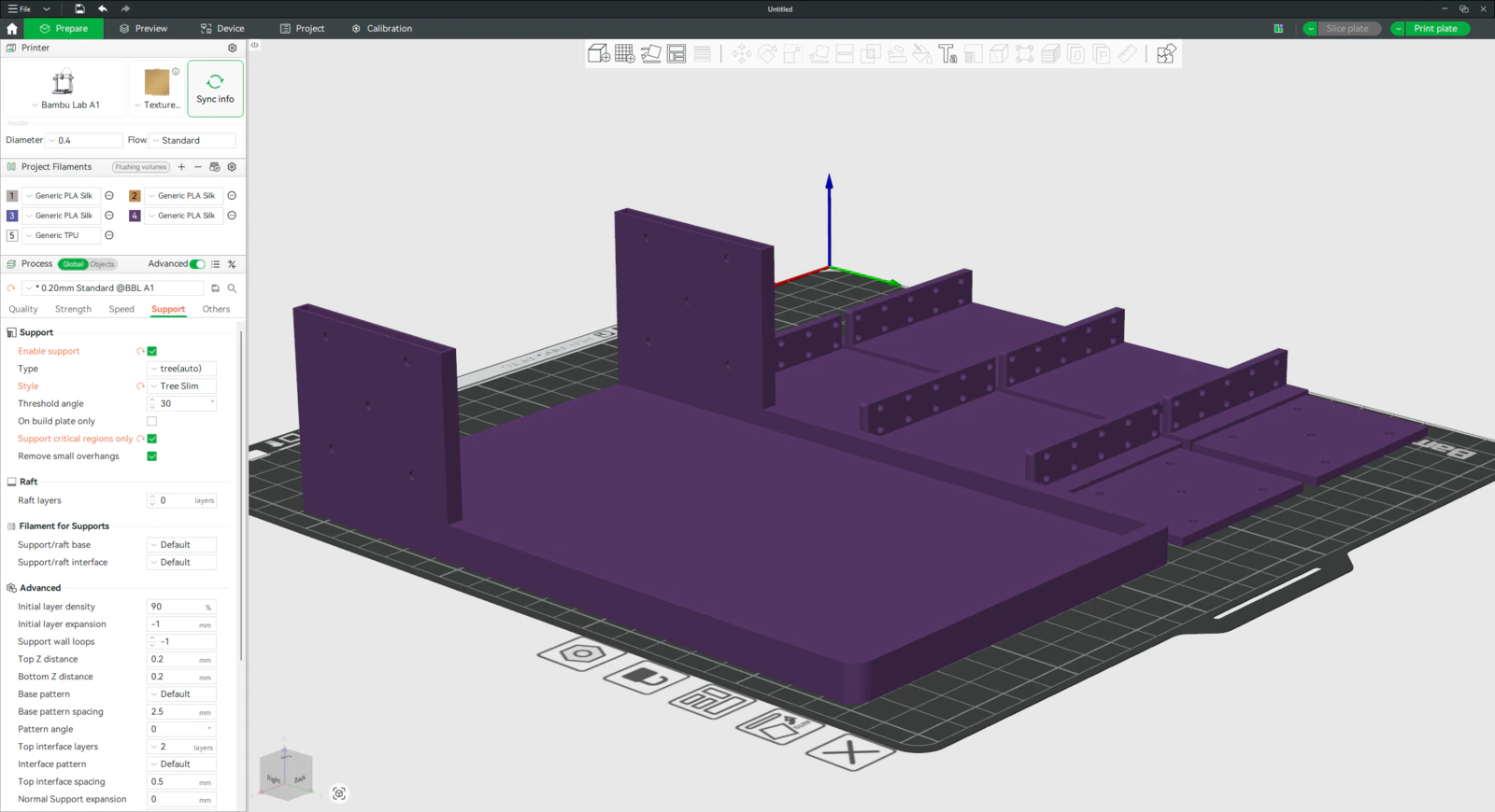
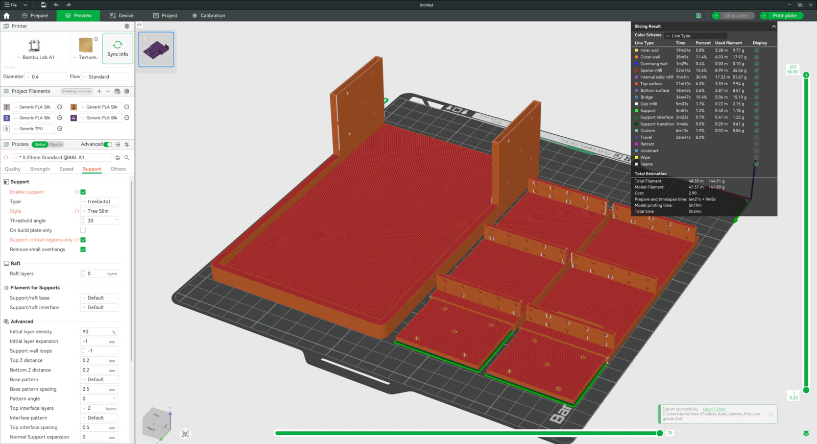
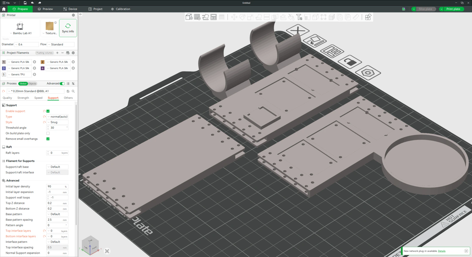
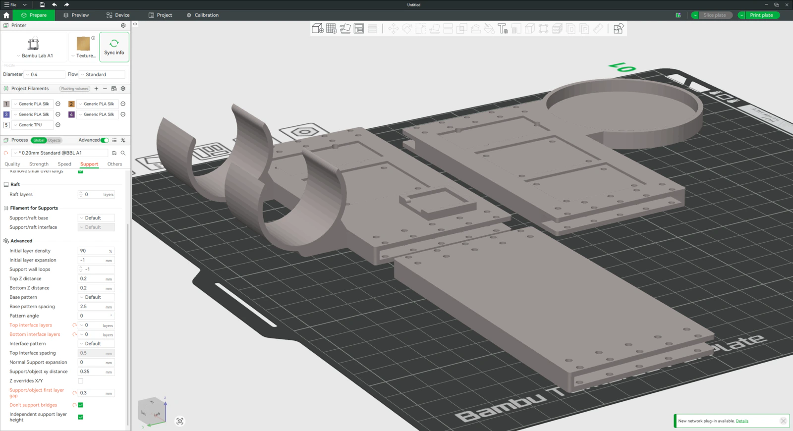
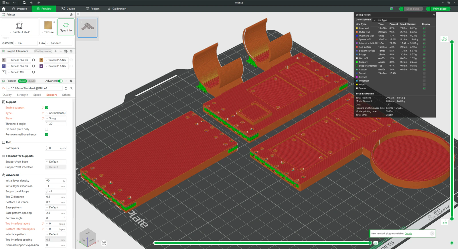
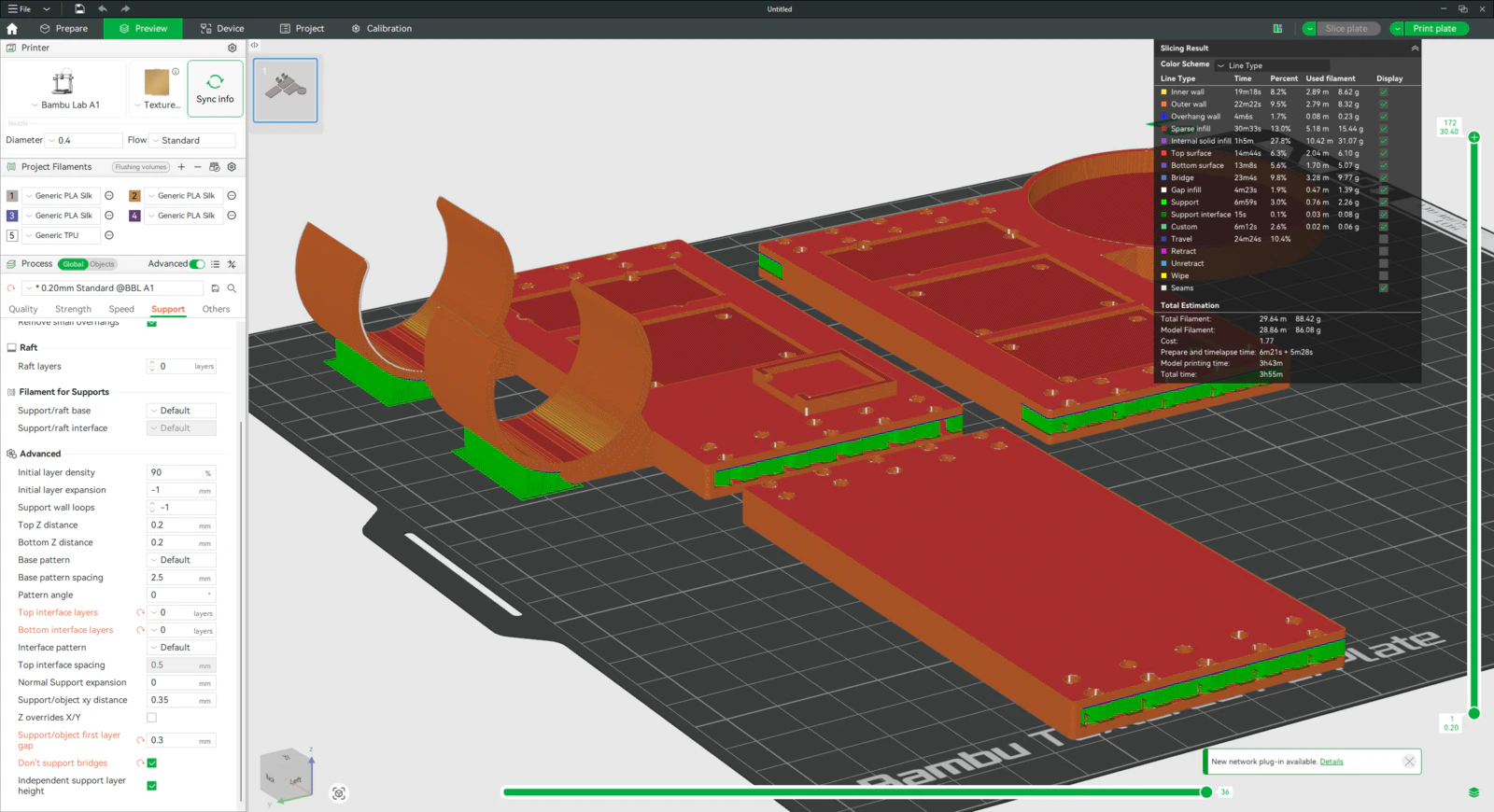
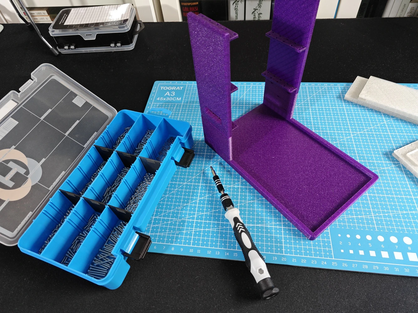
Step 9.b.1: Printing and assembling the lab assistant sensor ladder
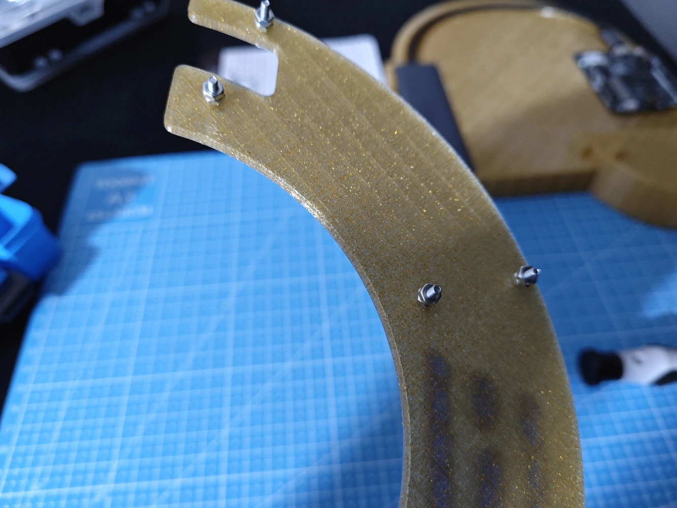
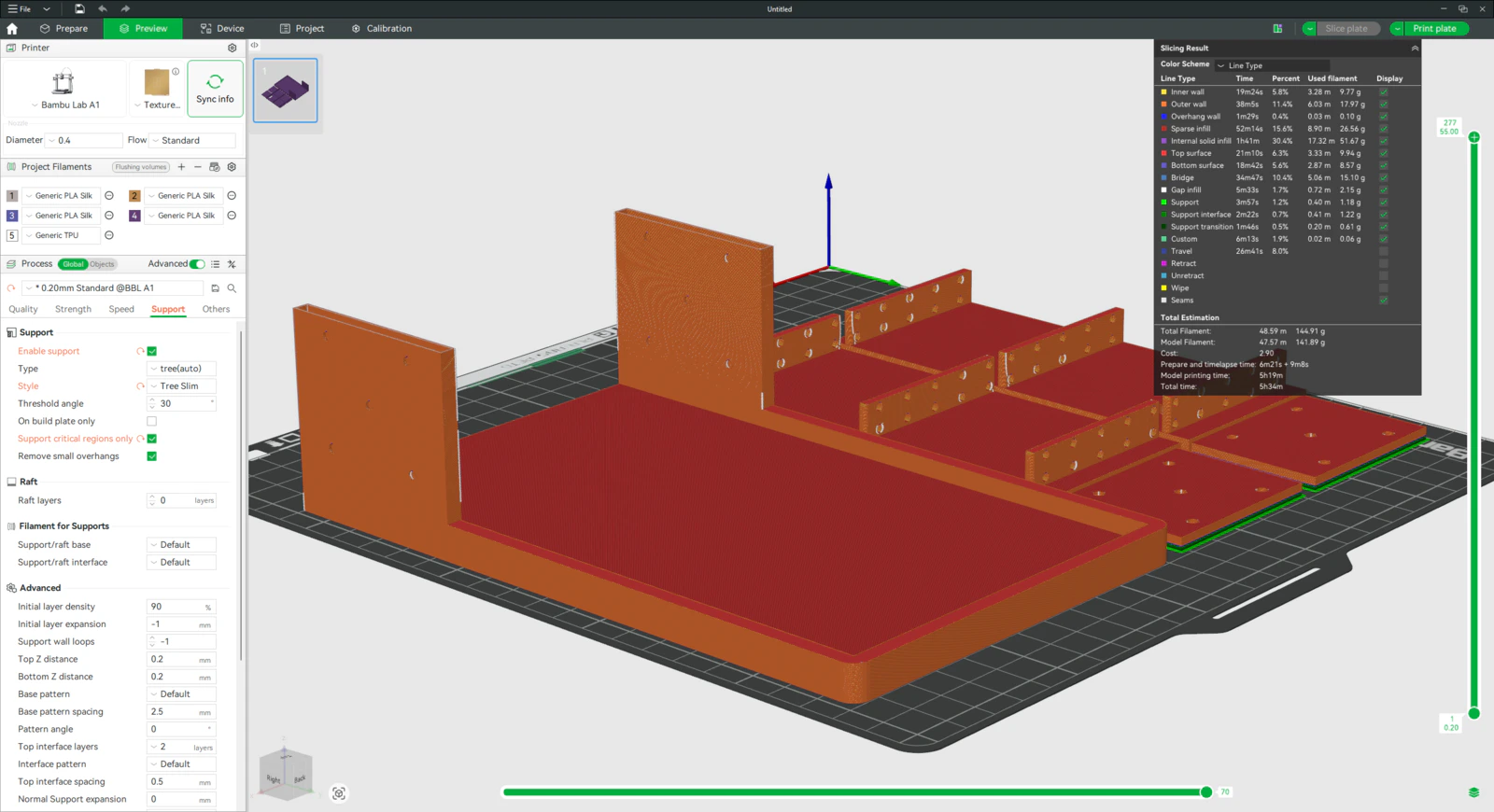
#️⃣ To print the sensor ladder walls precisely, I utilized tree (slim) supports and enabled the support critical regions only option, which avoids unsolicited support placements. #️⃣ Since the ladder rungs (rows) have notches that slide into the ladder walls, I needed to place supports very delicately to prevent extra friction or stuckness due to excess material. After some trial and error, I found that normal supports and the Snug support style with special settings work perfectly to print narrow grooves with the e-Twinkling filament type.- Type ➡️ normal (auto)
- Style ➡️ Snug
- Top interface layers ➡️ 0
- Bottom interface layers ➡️ 0
- Support/object first layer gap ➡️ 0.3
- Don’t support bridges ➡️ ✅
Step 9.c: Final adjustments and installing the analog interface PCB
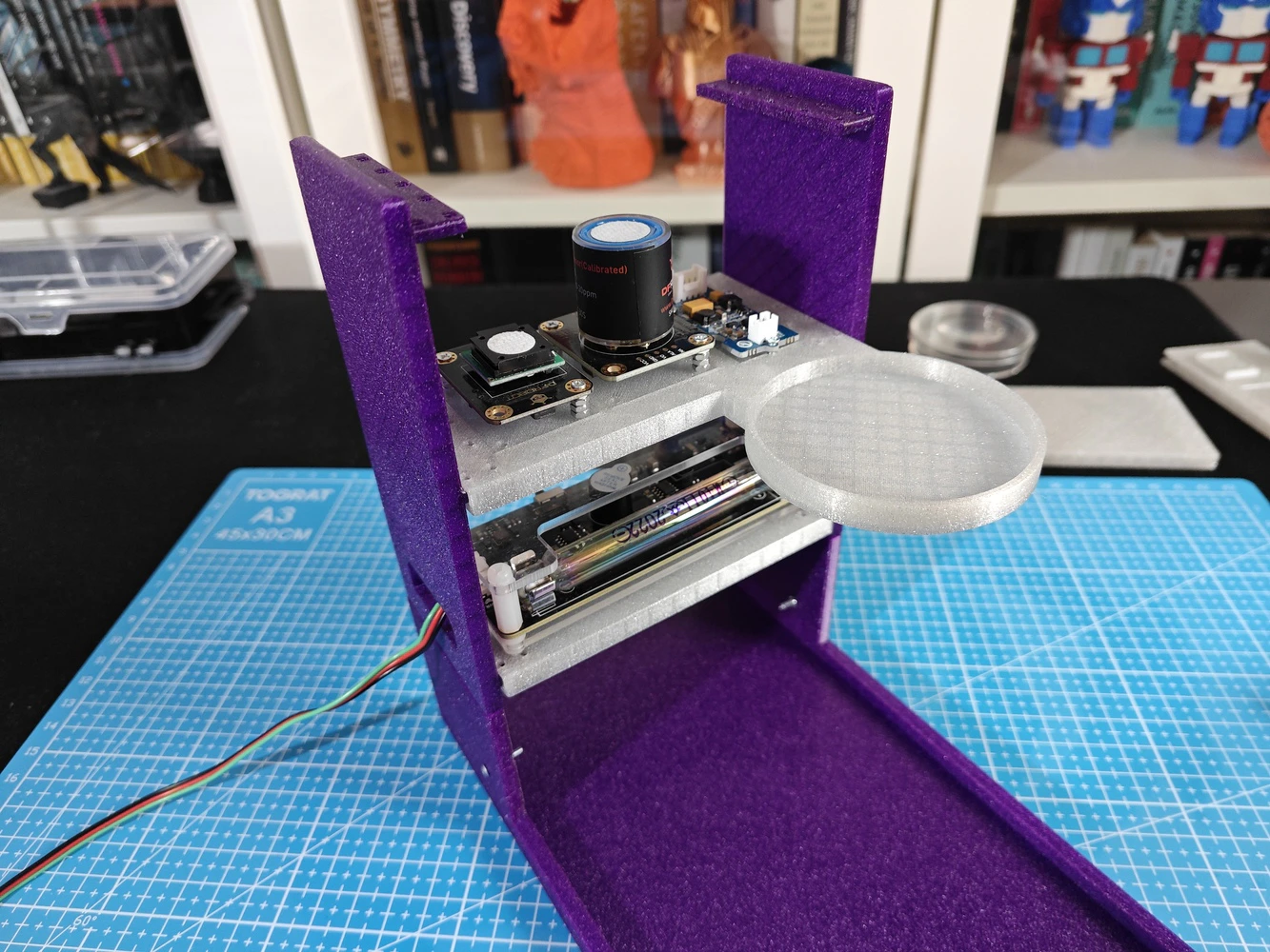
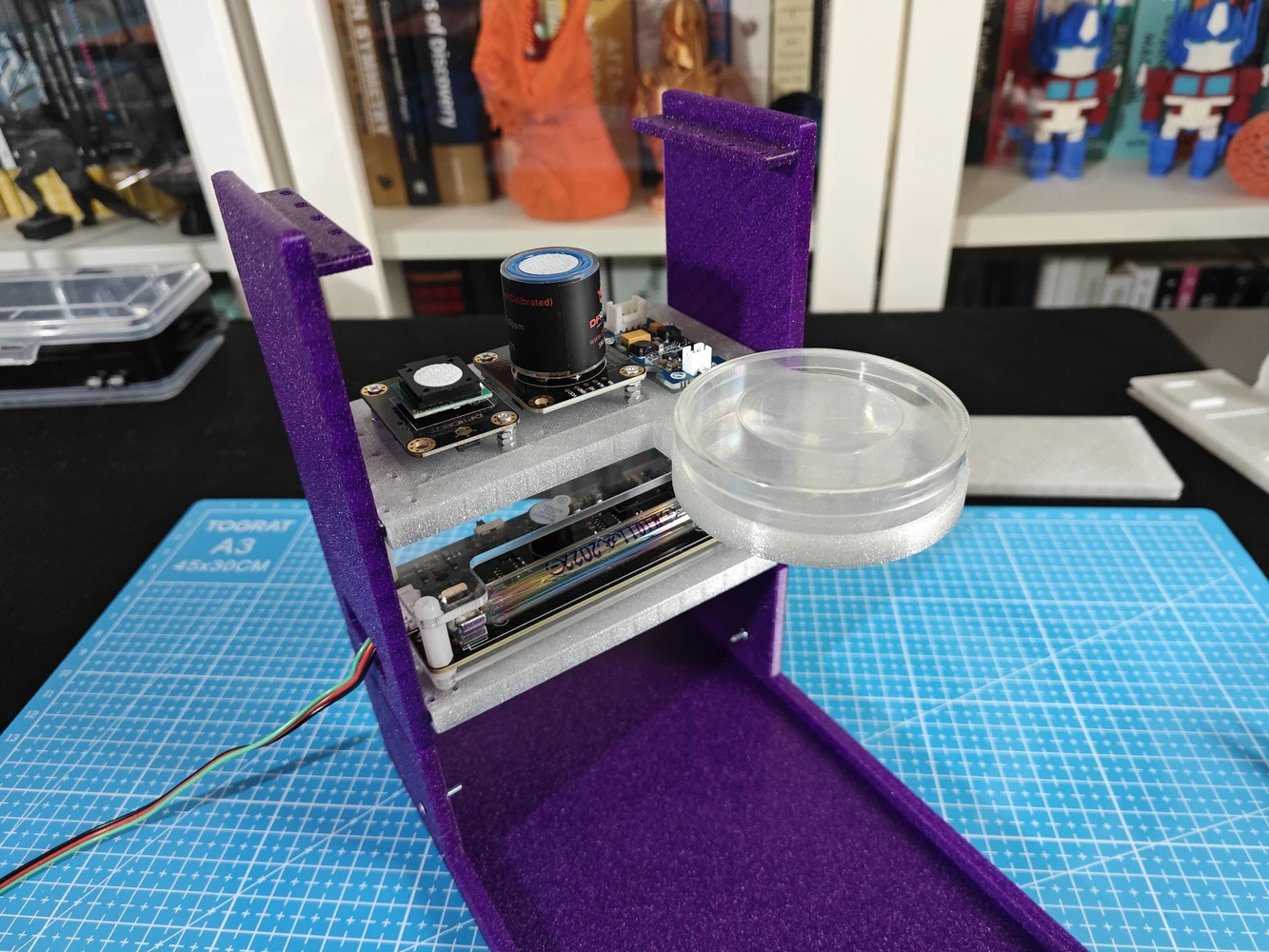
#️⃣ After completing the lab assistant base and sensor ladder assembly, I attached the analog interface PCB to the Arduino UNO Q via the dedicated male pin headers. Thanks to the PCB’s guiding features (holes) and the corresponding base pegs, it was effortless to align and secure the PCB.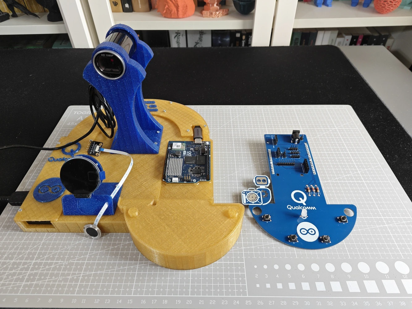
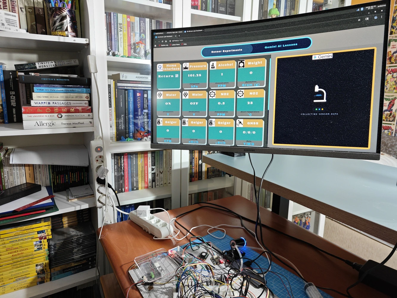
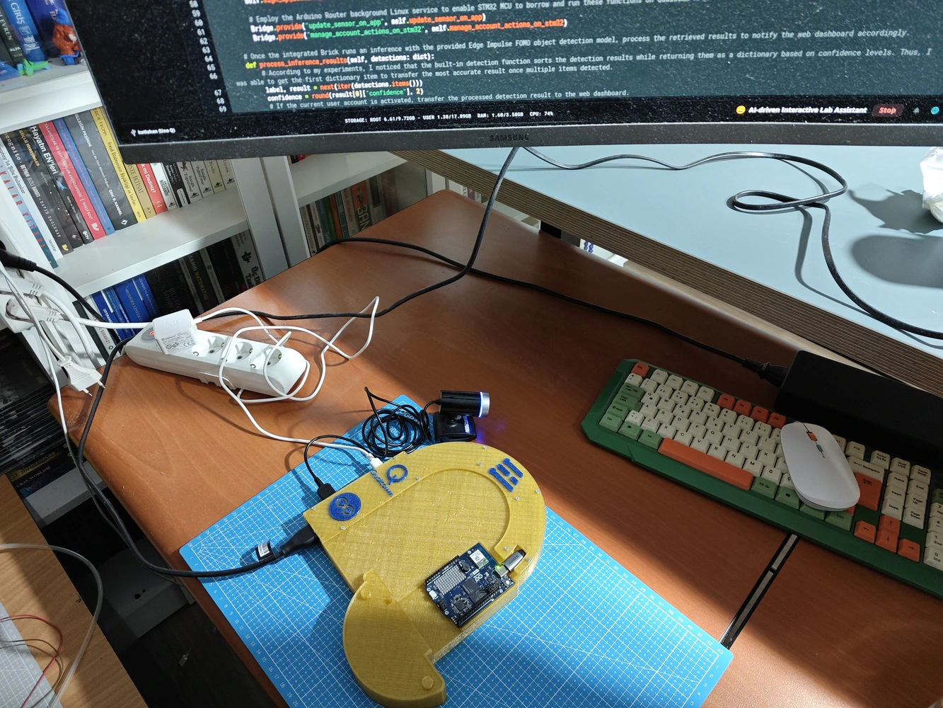
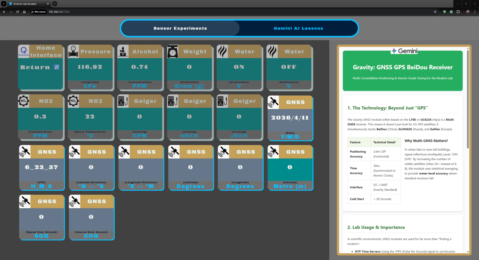
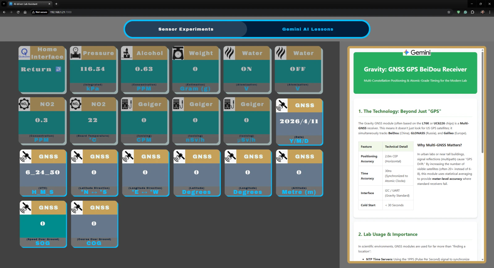
Outcomes: Conducting LLM-assisted lab experiments with the integrated lab sensors
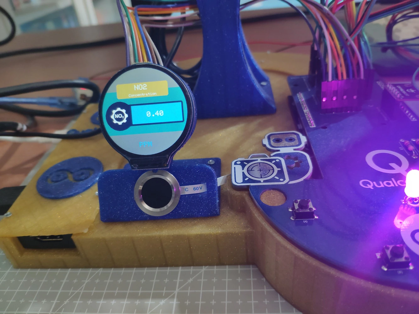
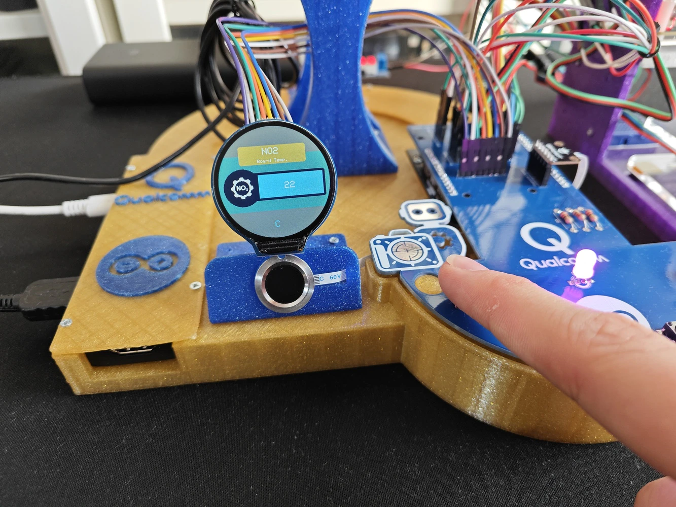
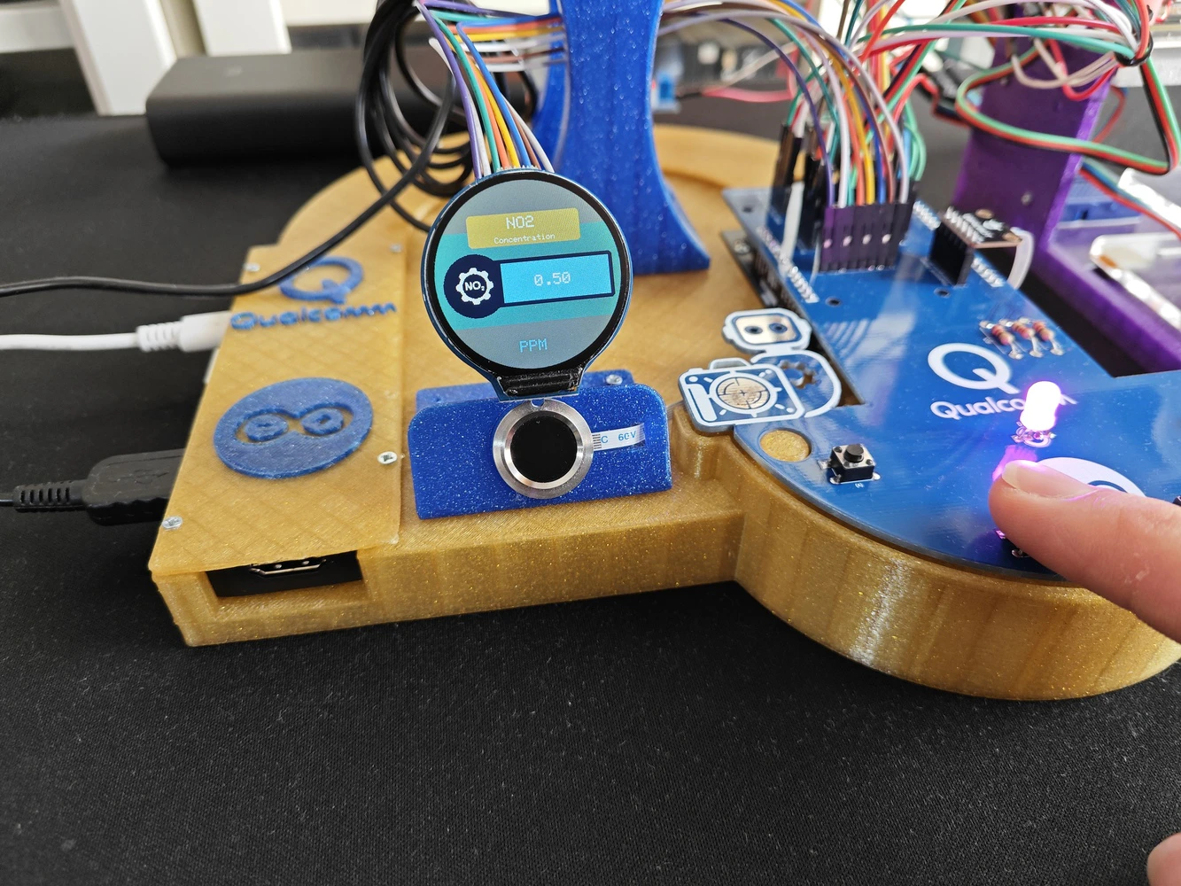
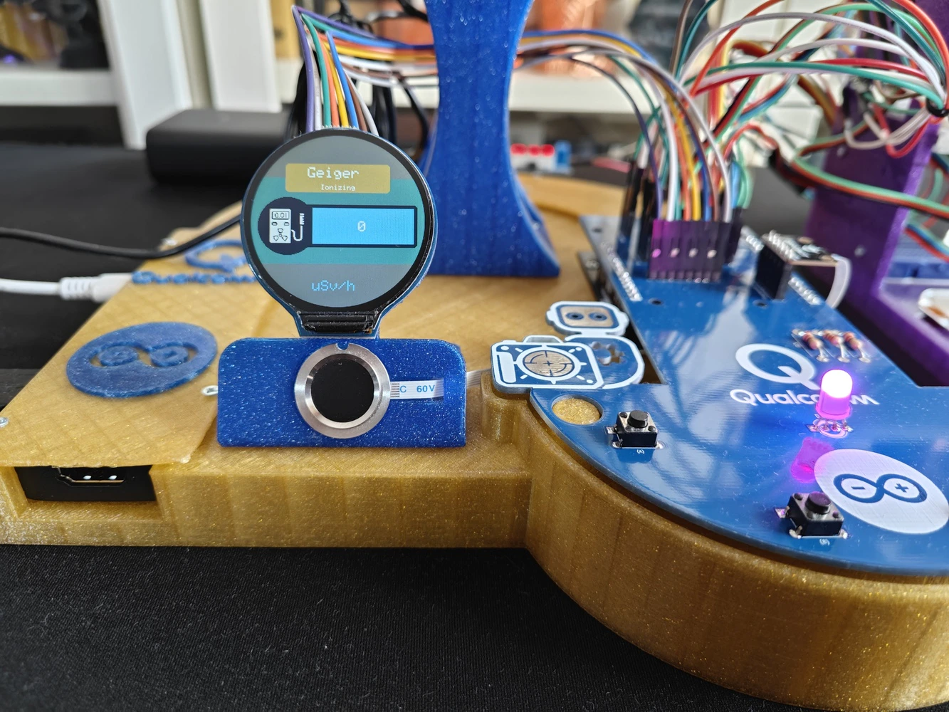
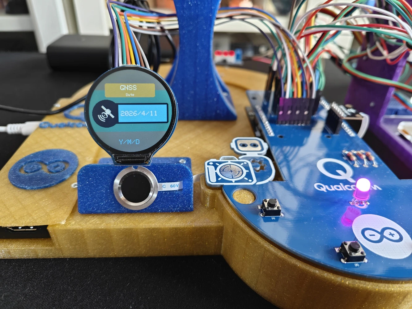
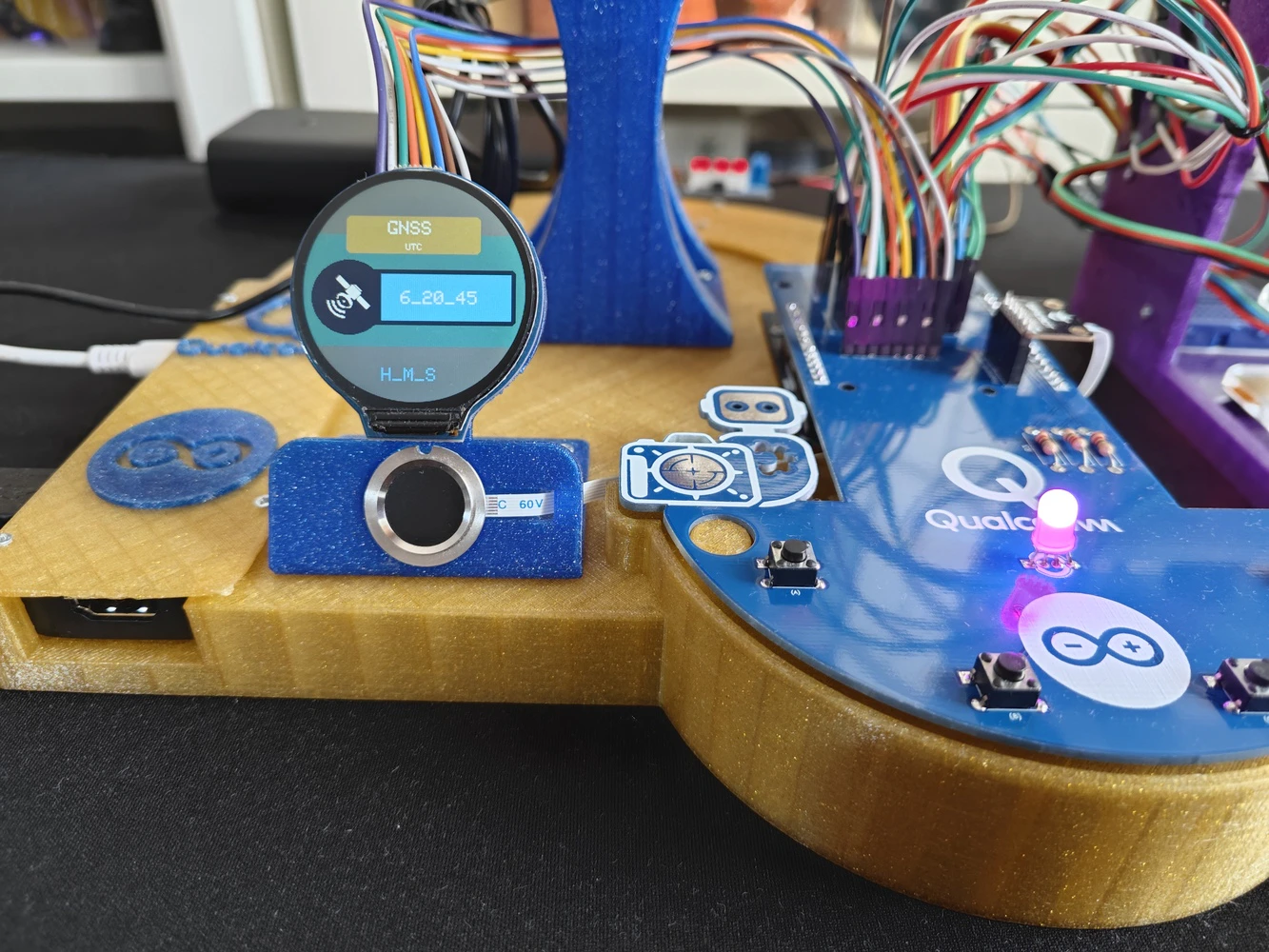
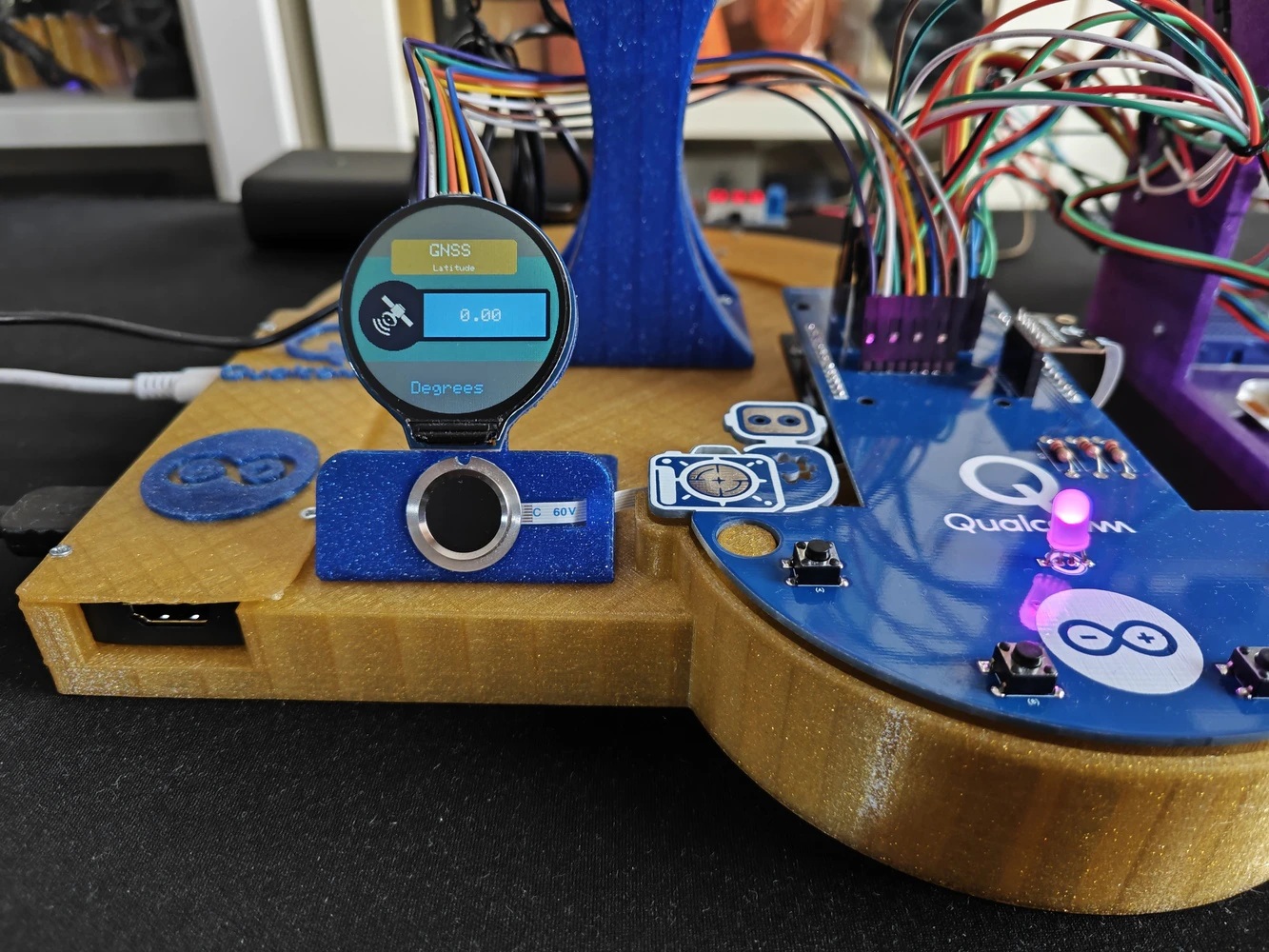
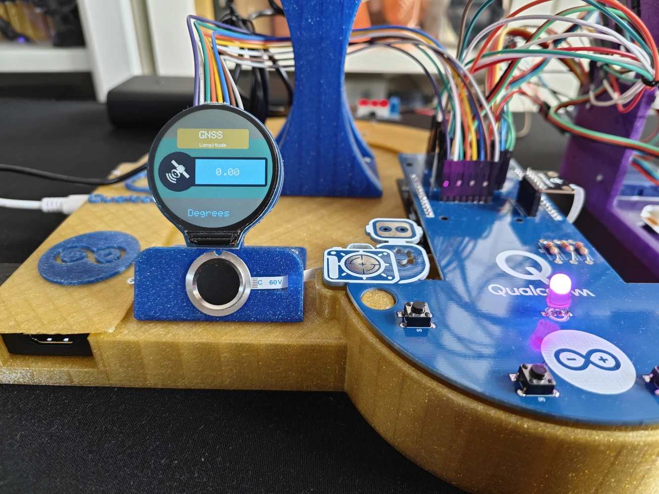
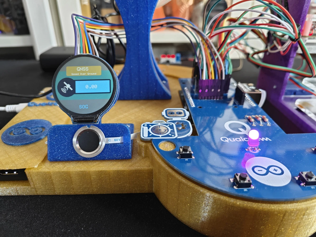
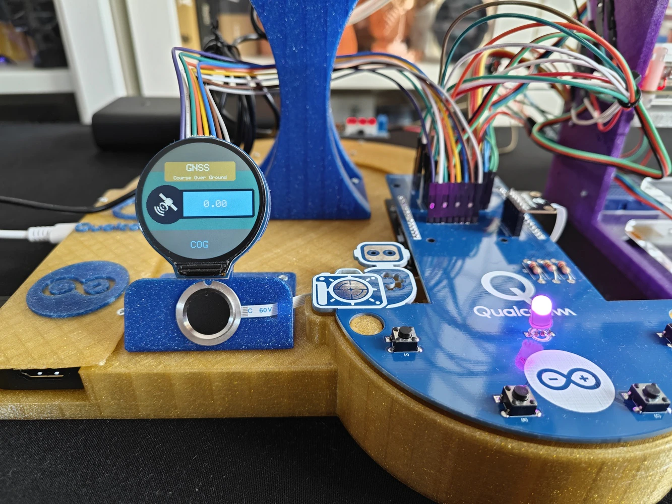
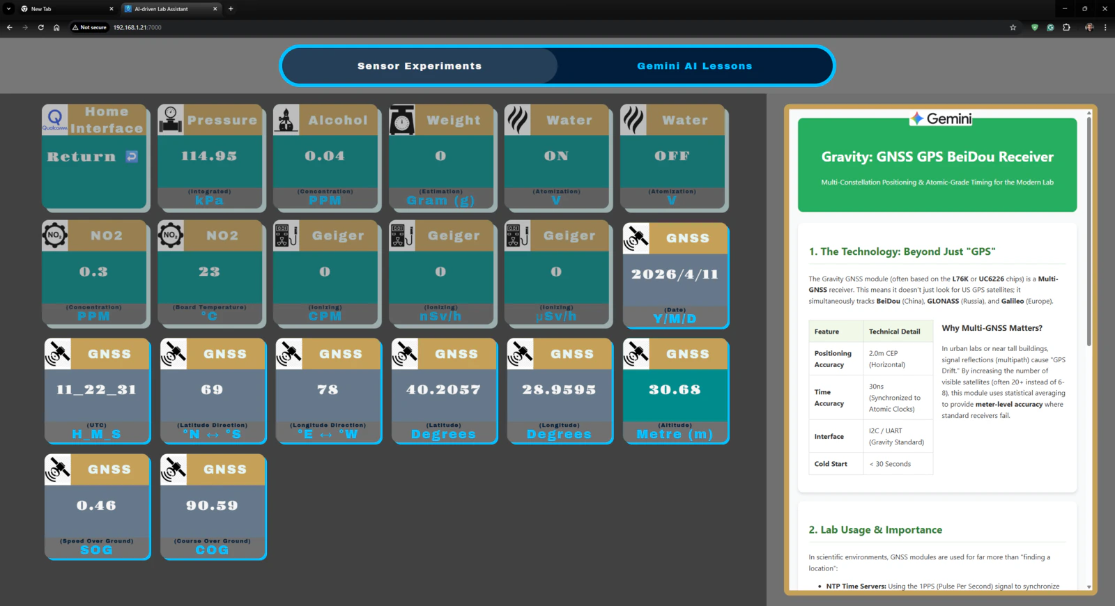
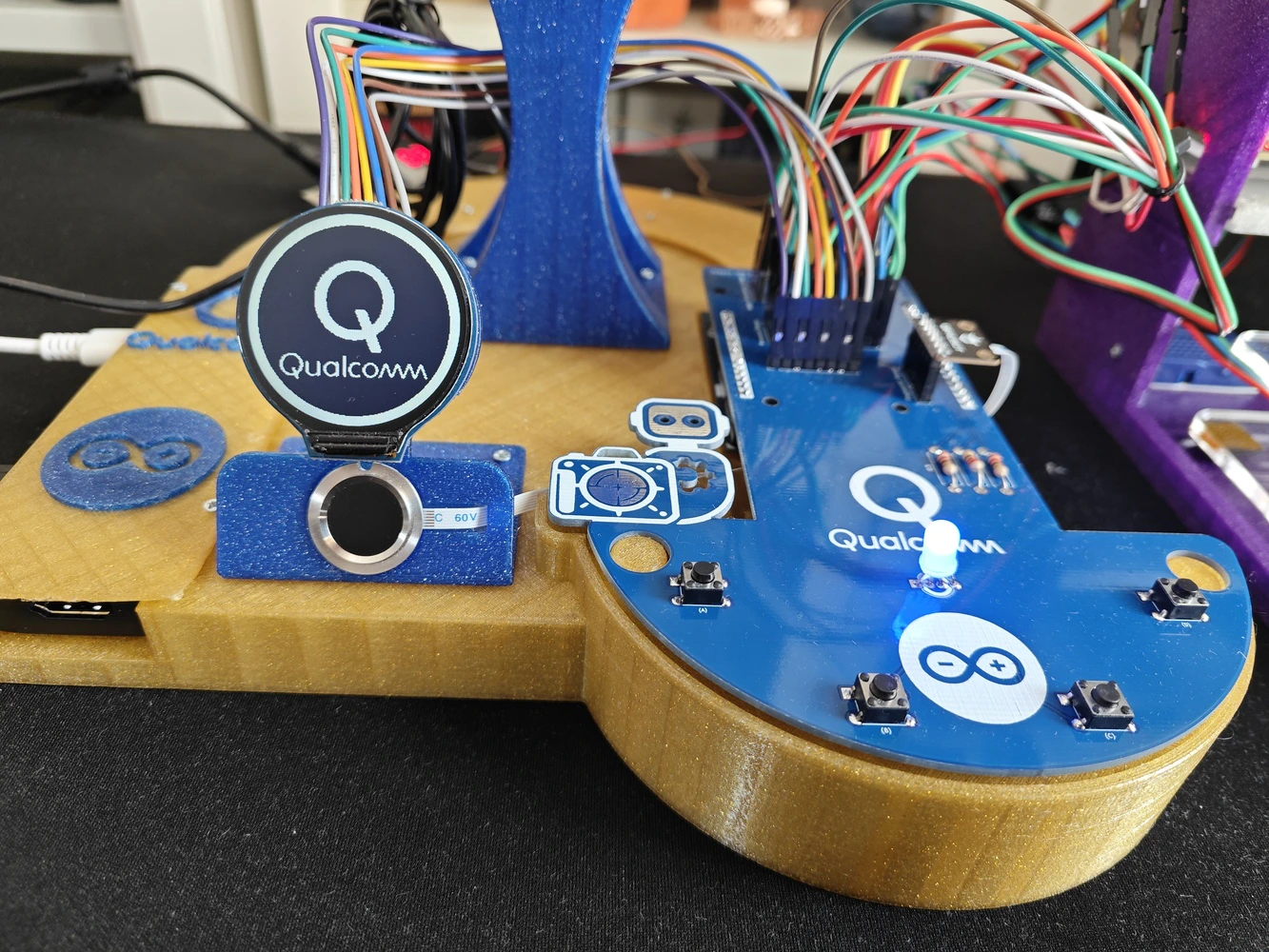
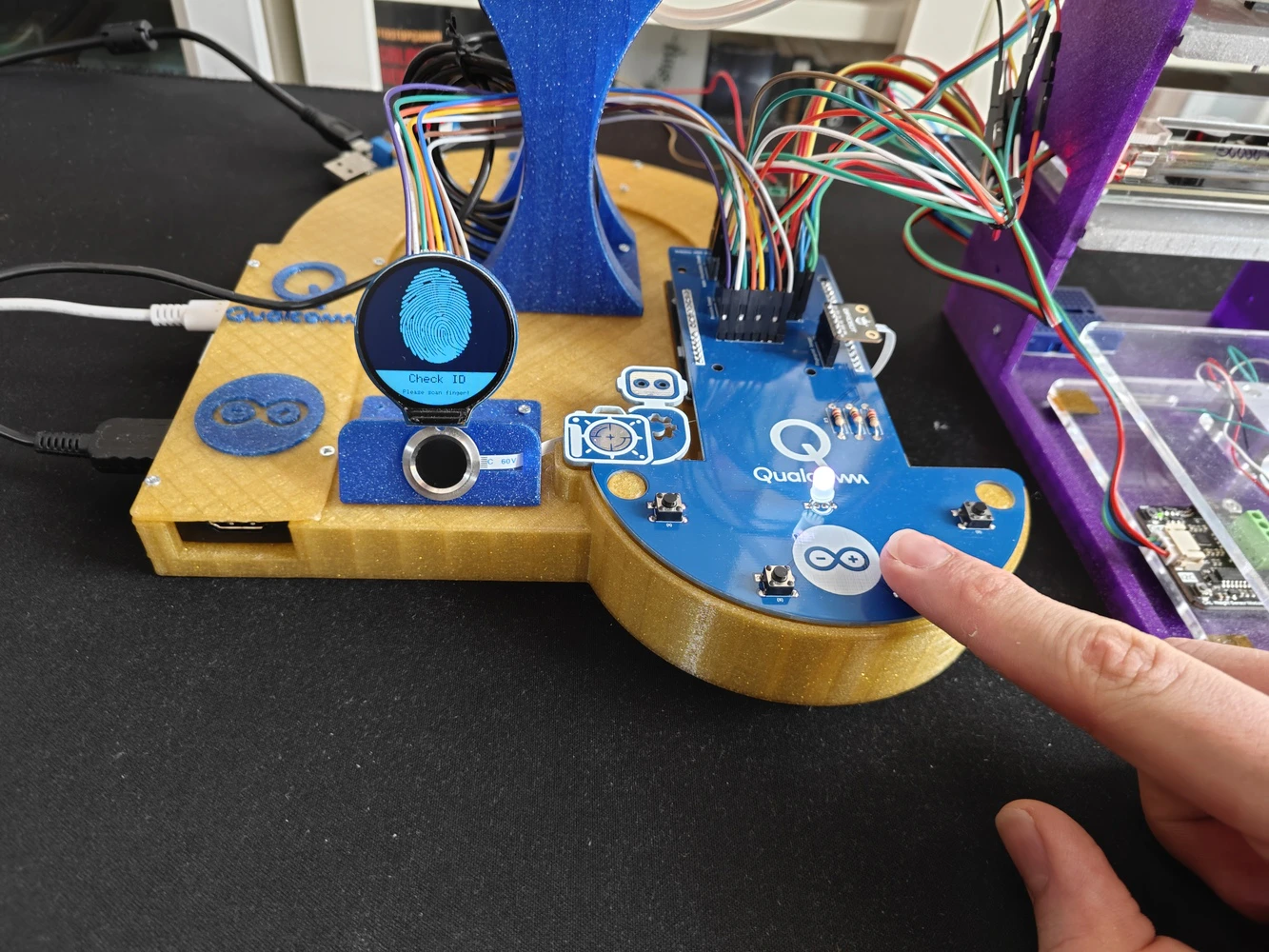
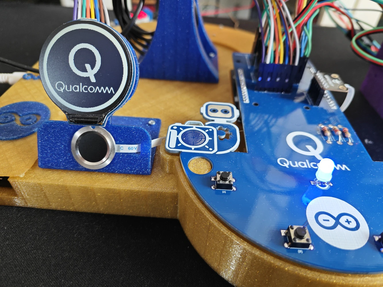
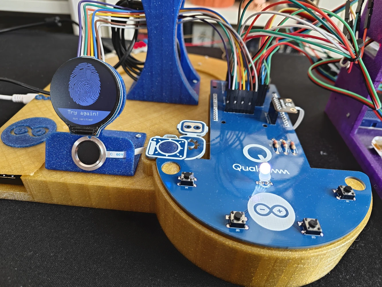
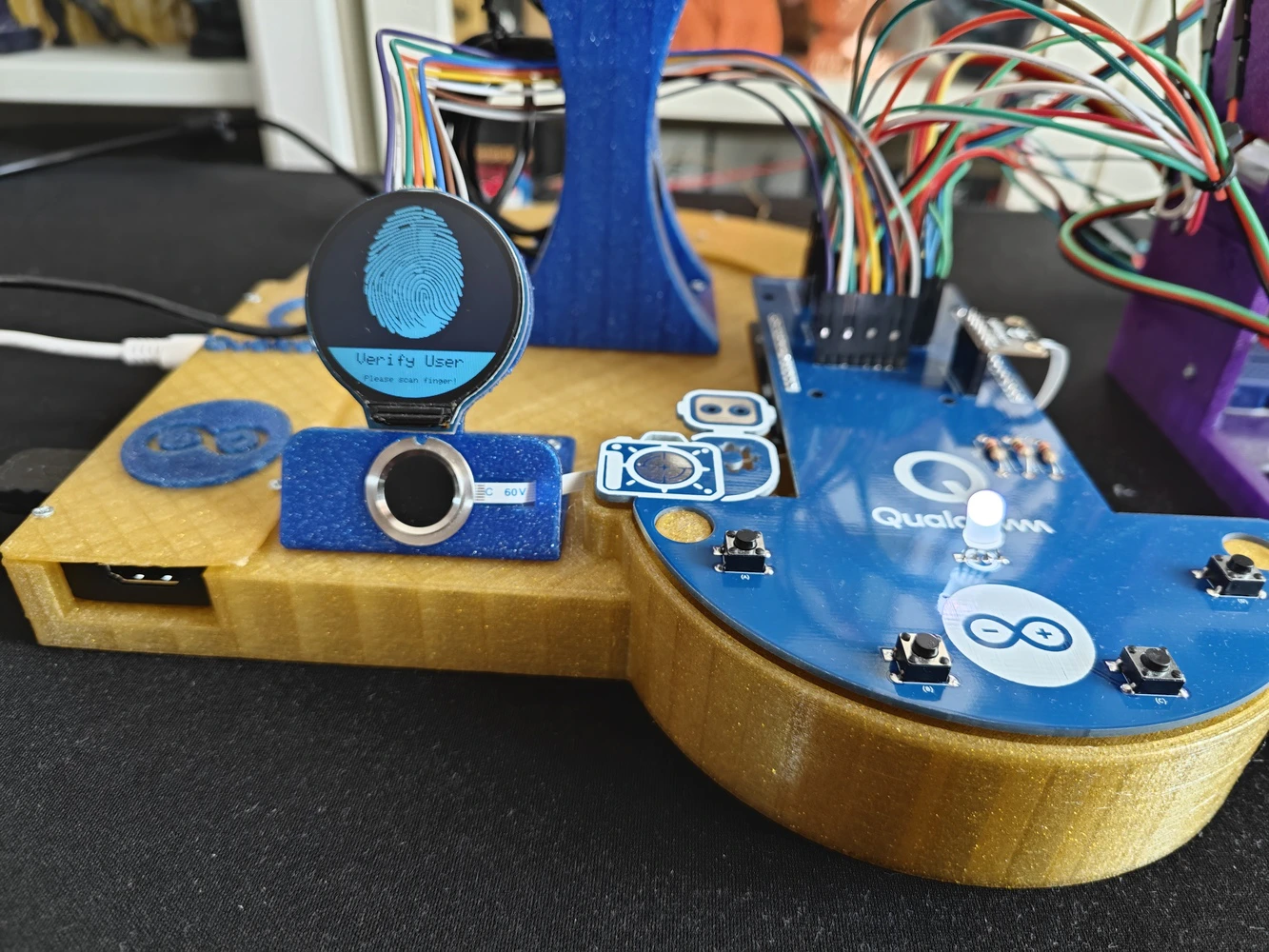
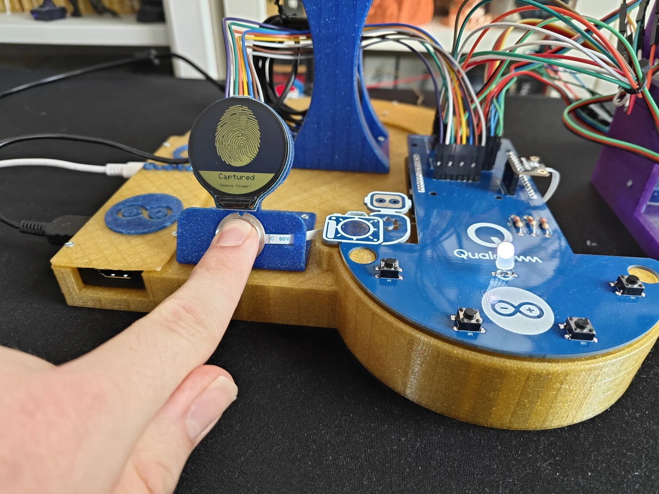
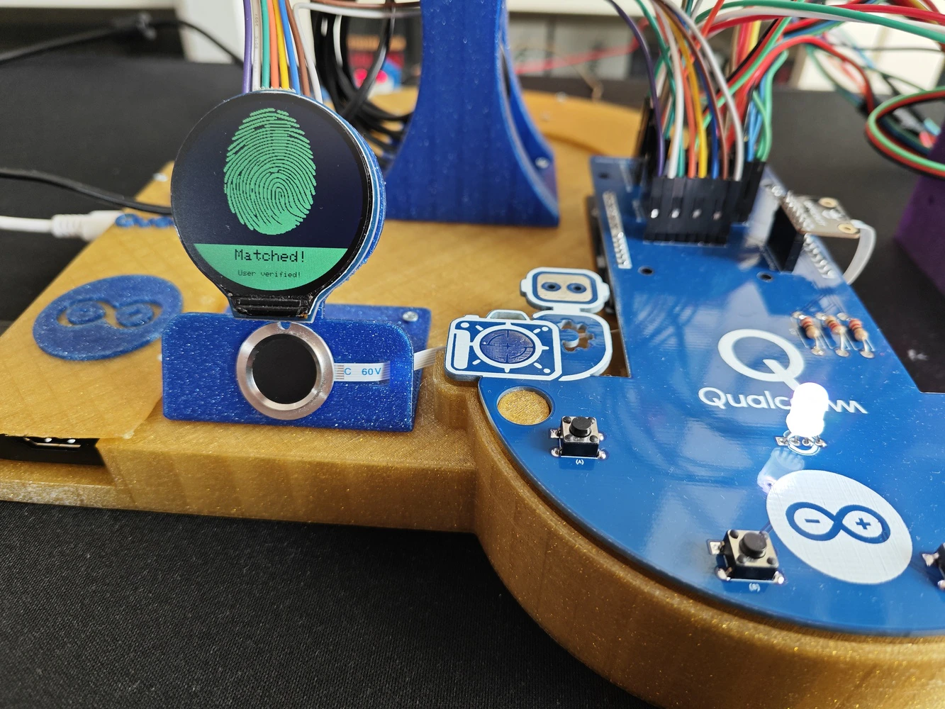
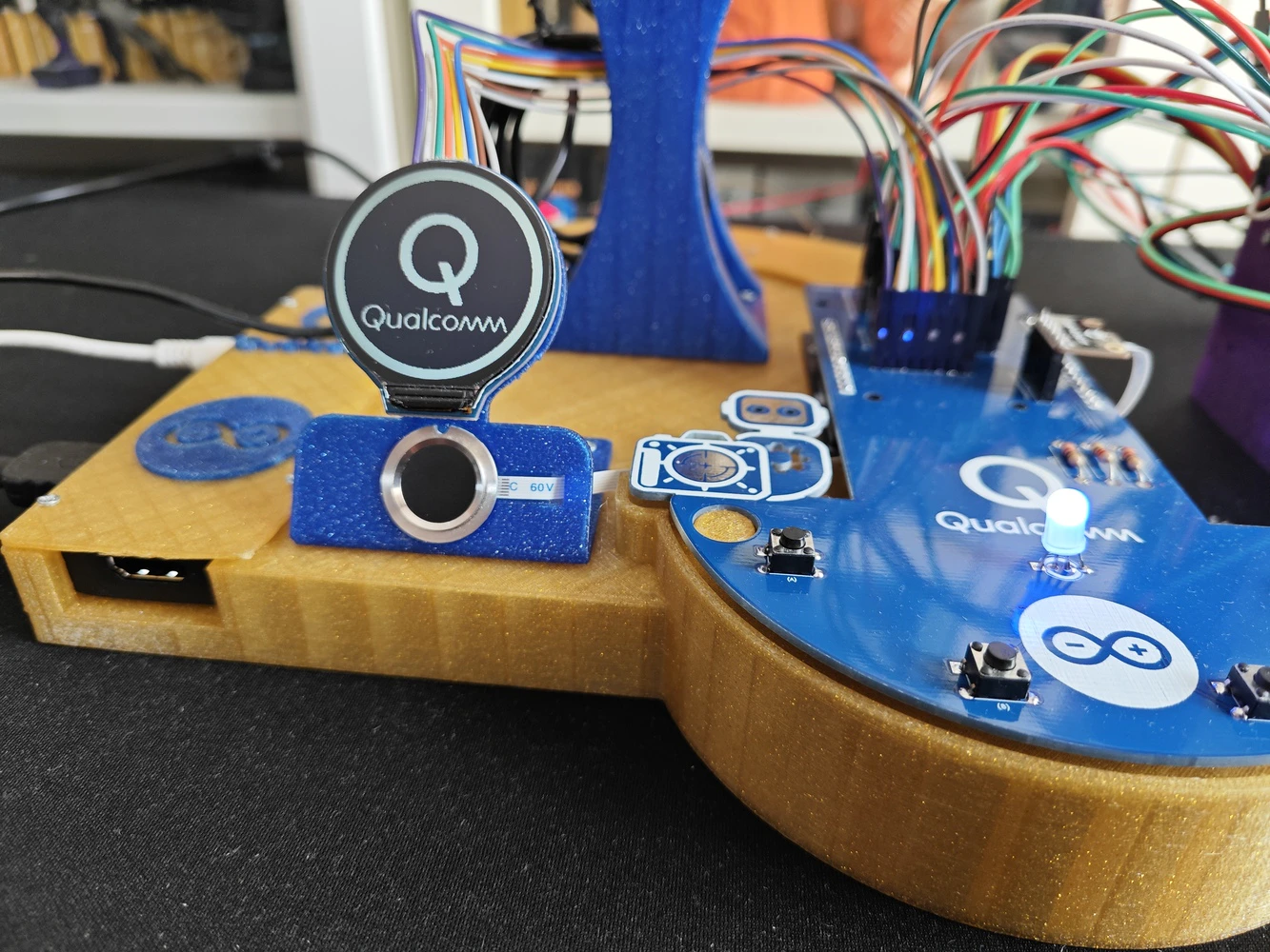
🤖🔬🧬🧫 Once the user initiates the ancillary lab assistant, the assistant activates the home (default) state on the analog interface and waits for user inputs. 🤖🔬🧬🧫 After initiating a different analog interface state, the assistant lets the user return to the home (default) state by pressing the control button D.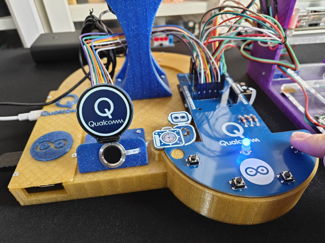
- Control button A ➡ Next (+)
- Control button B ➡ Previous (-)
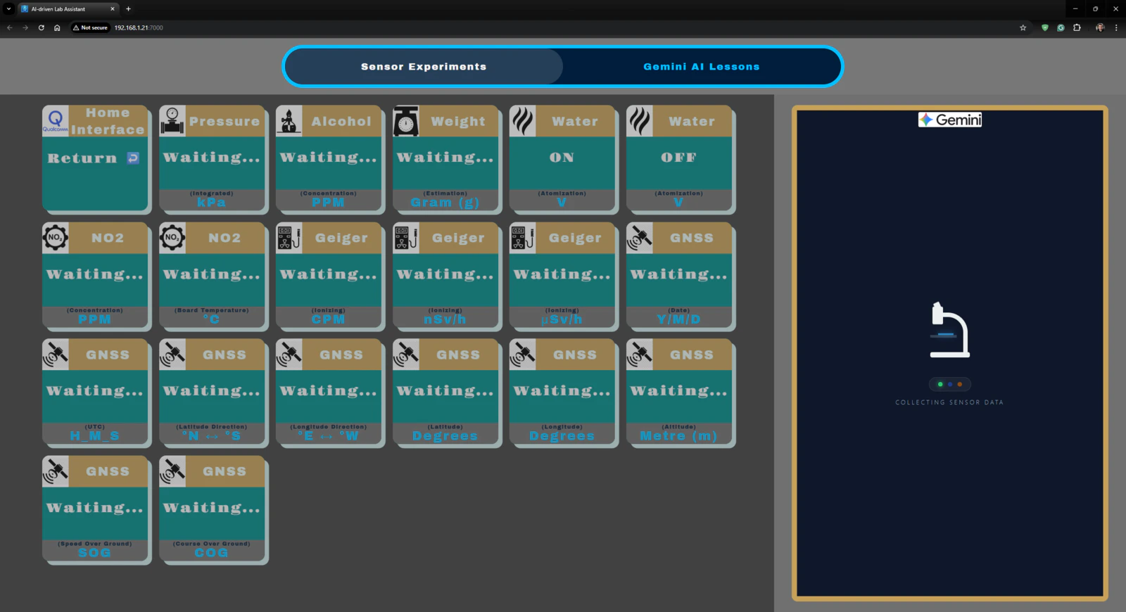


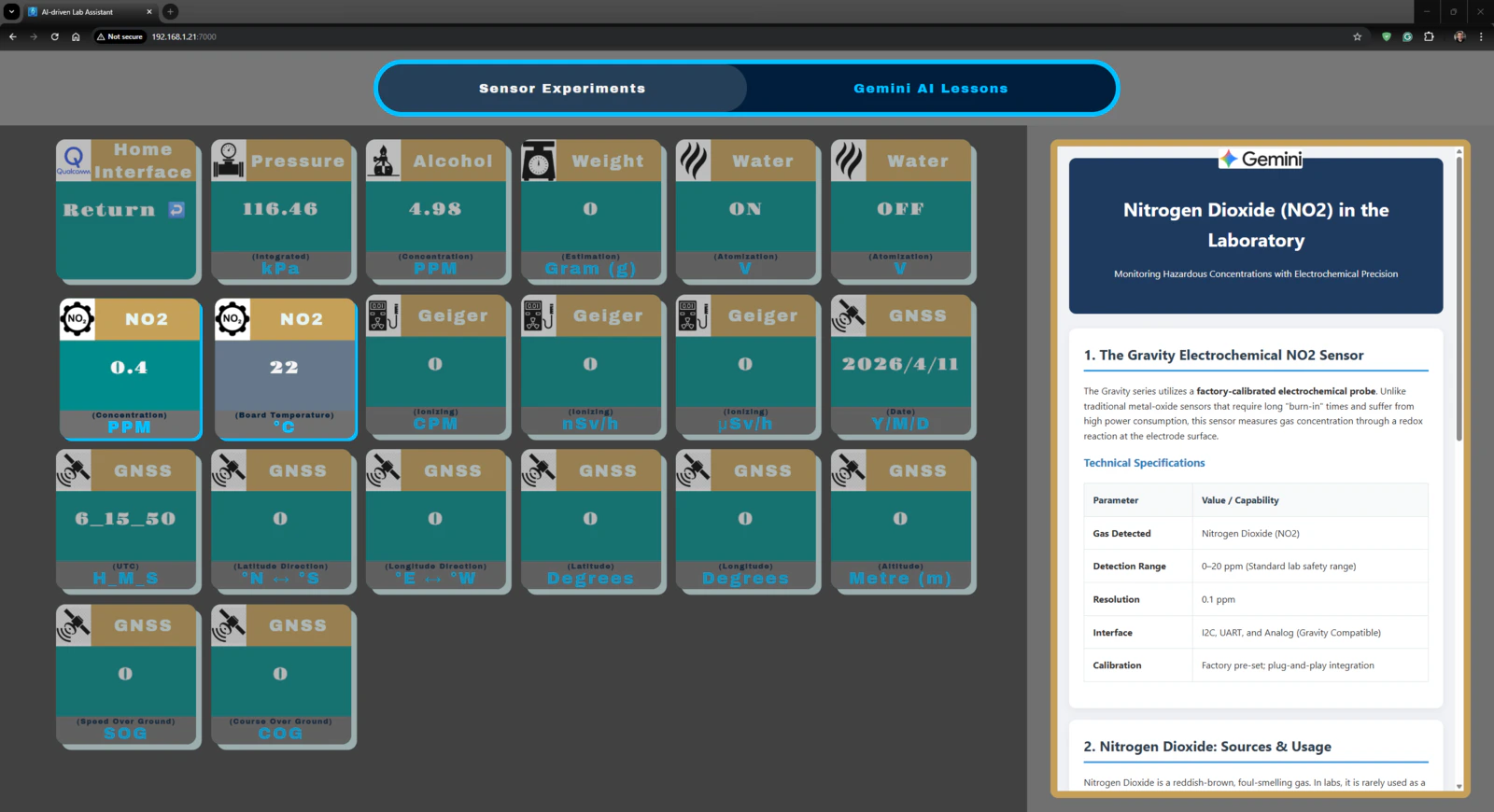


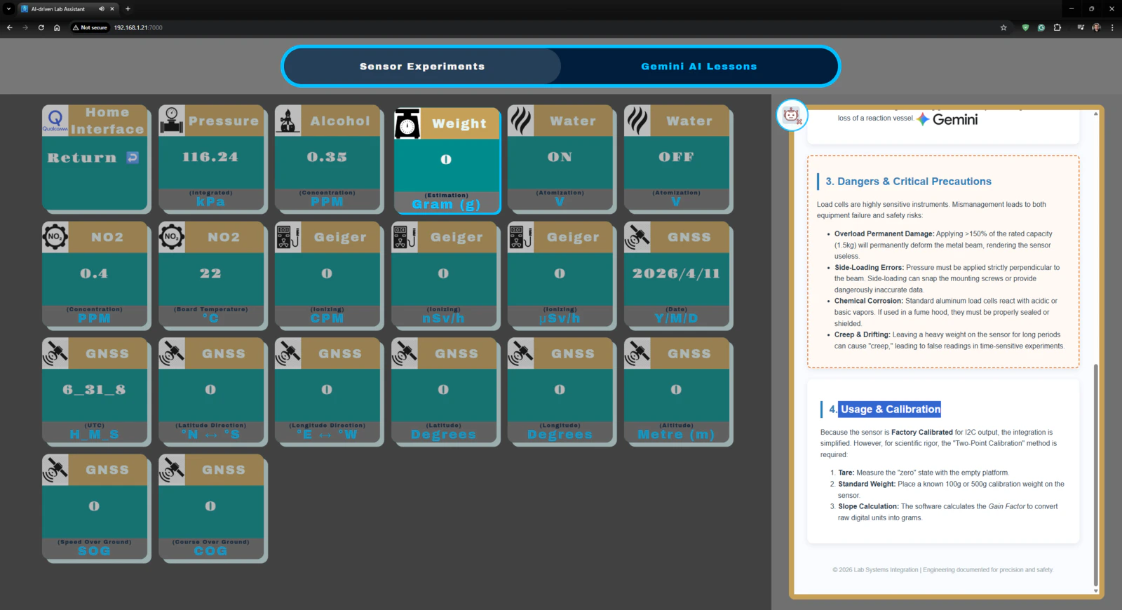
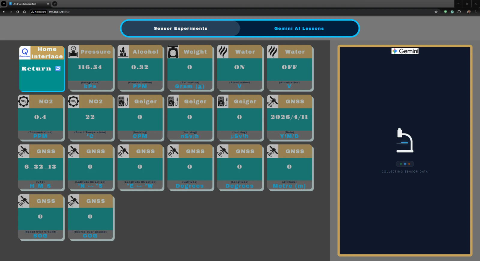
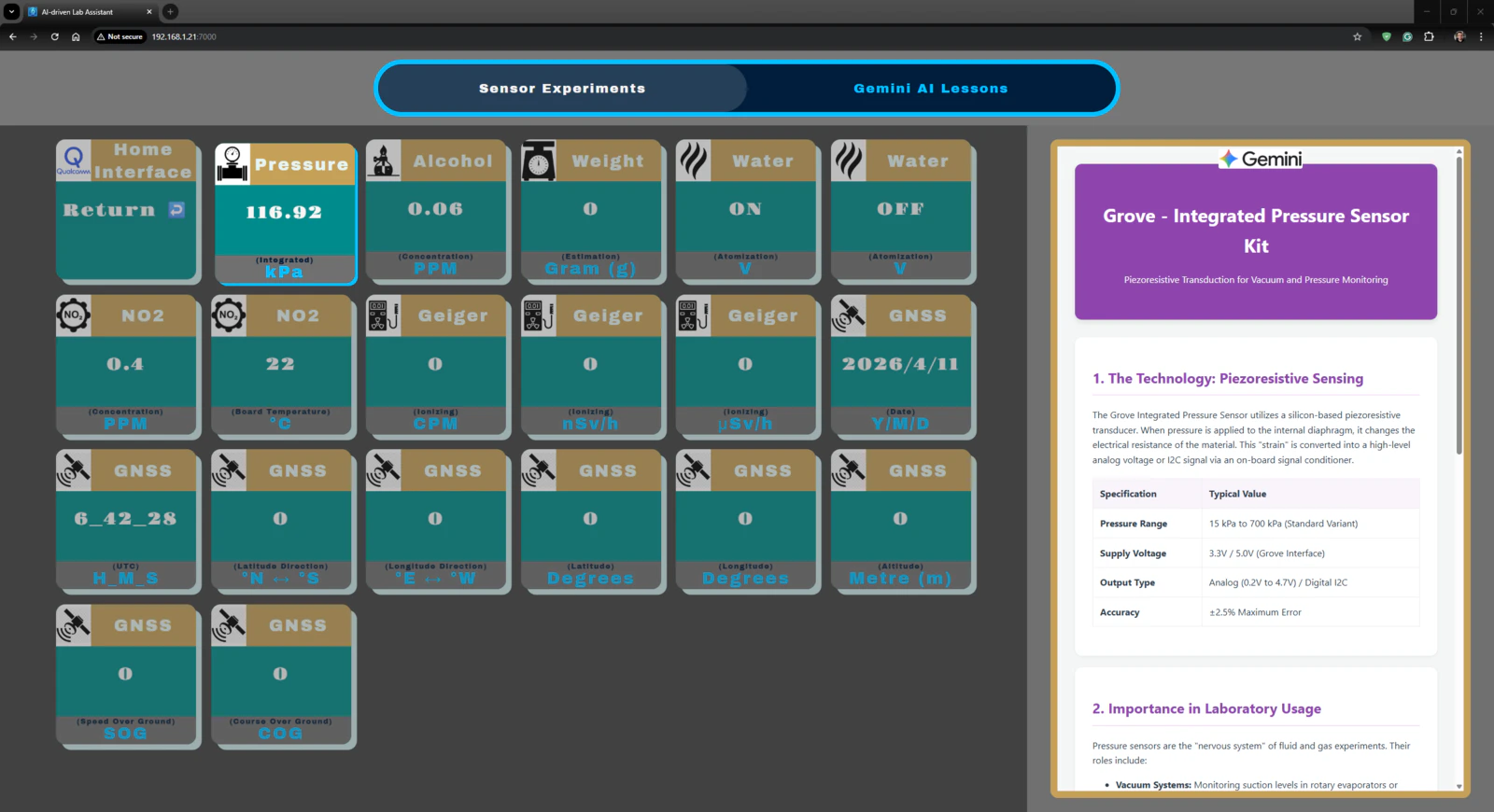


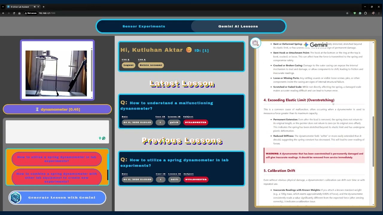
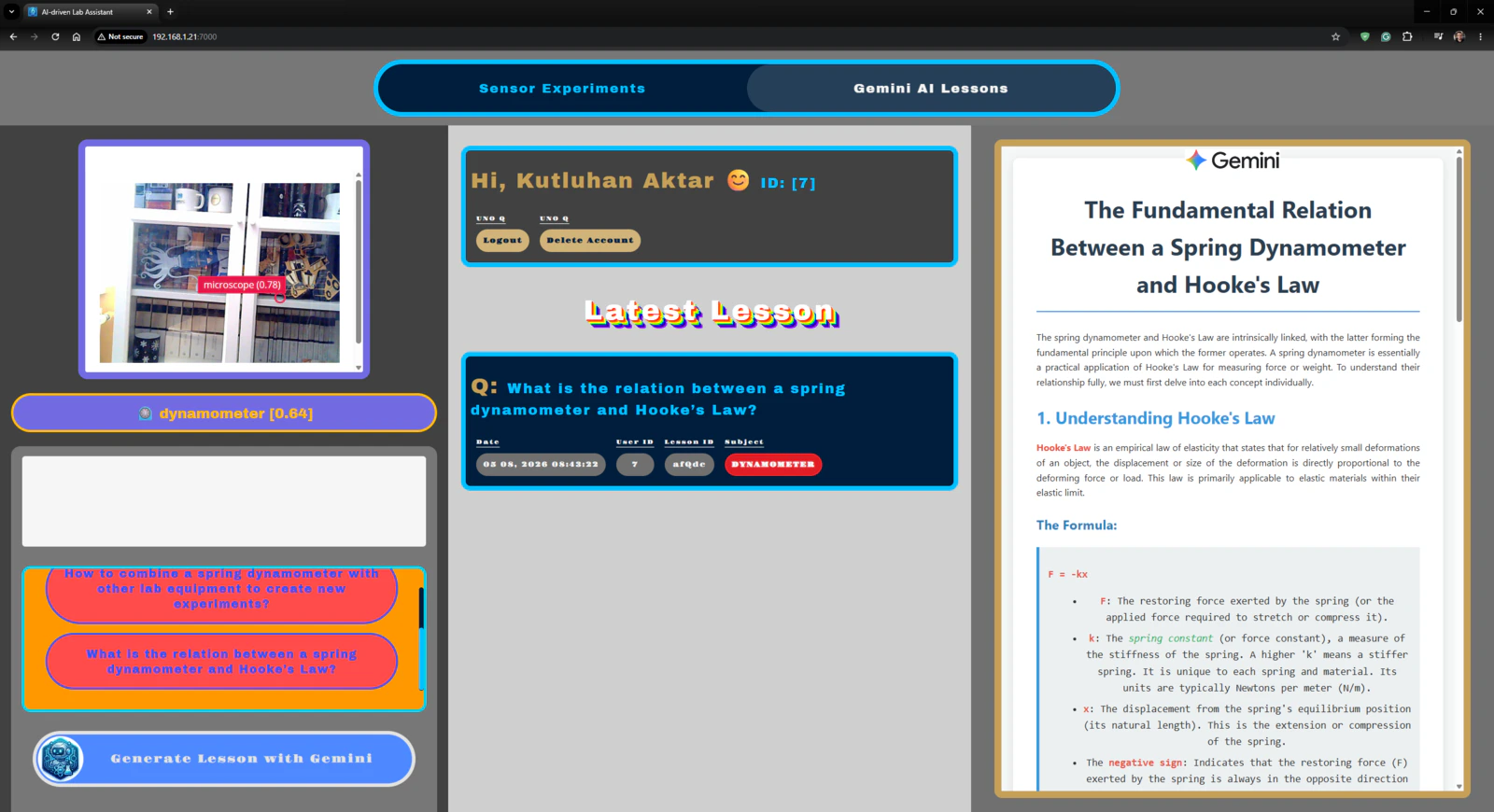
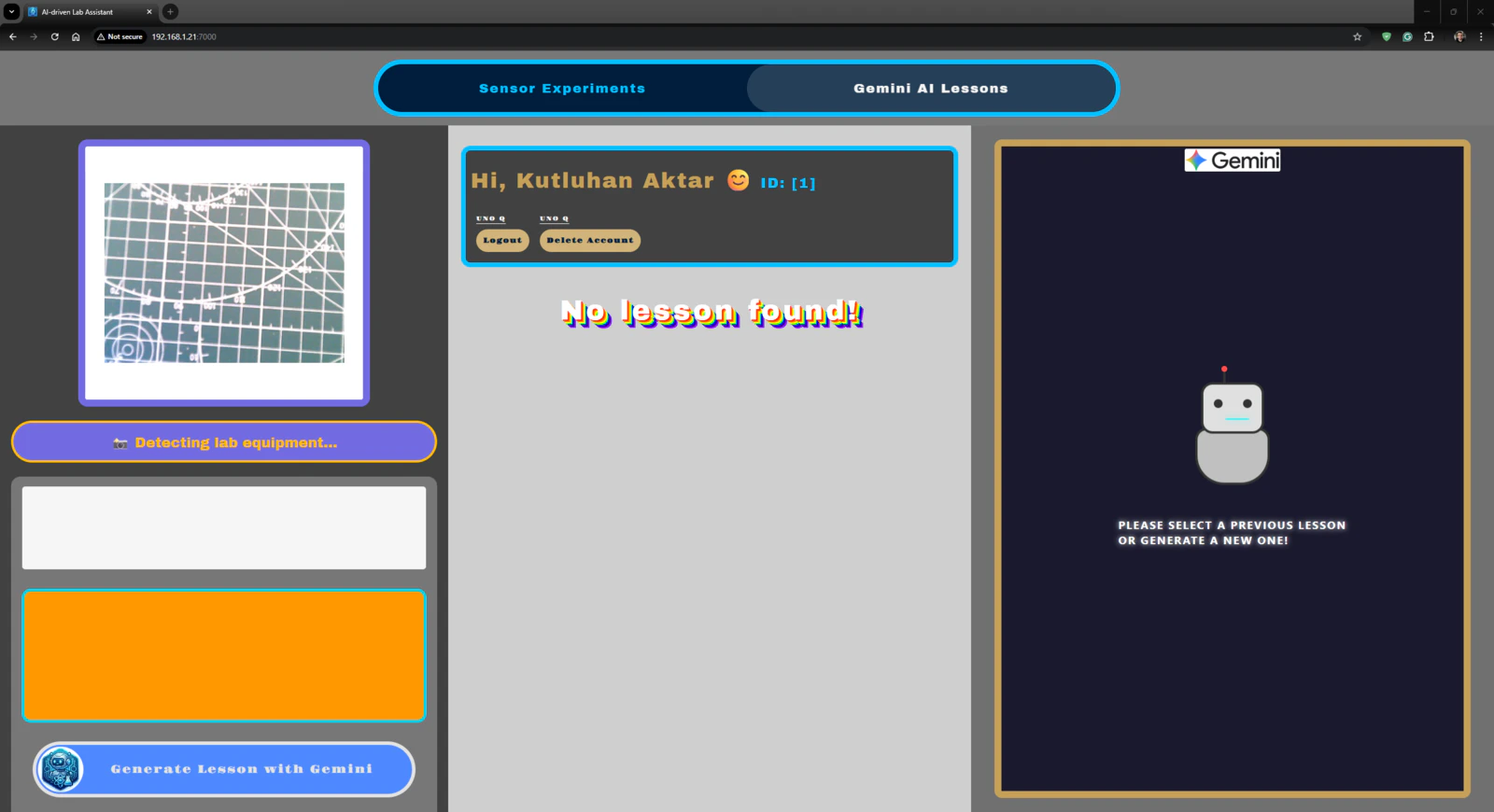
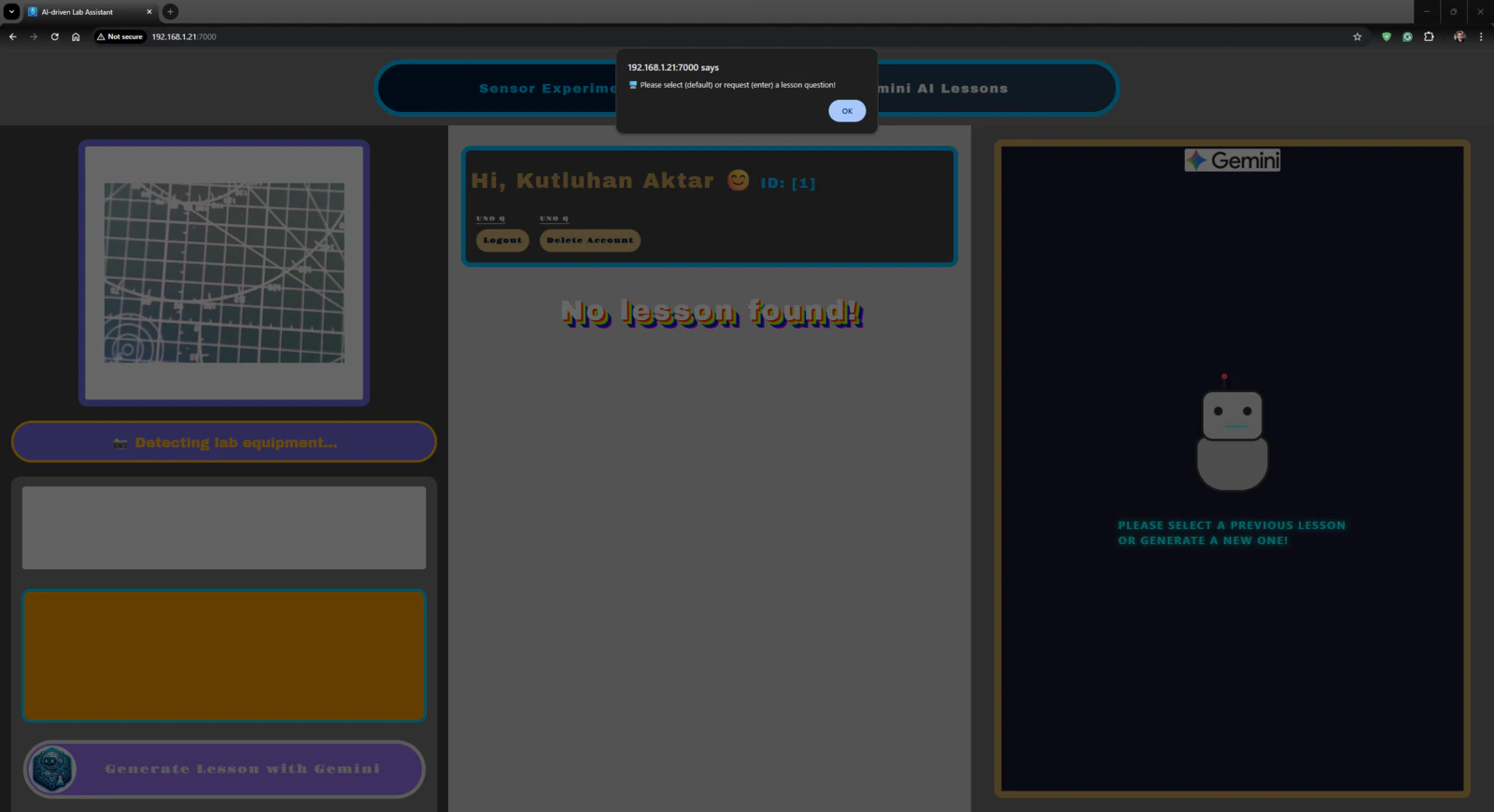
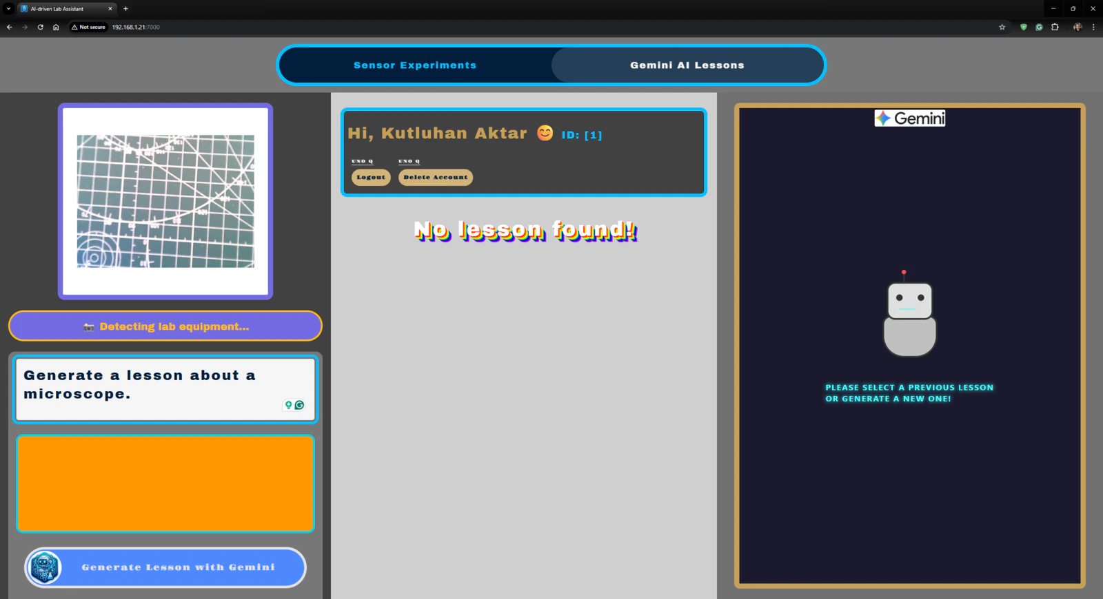
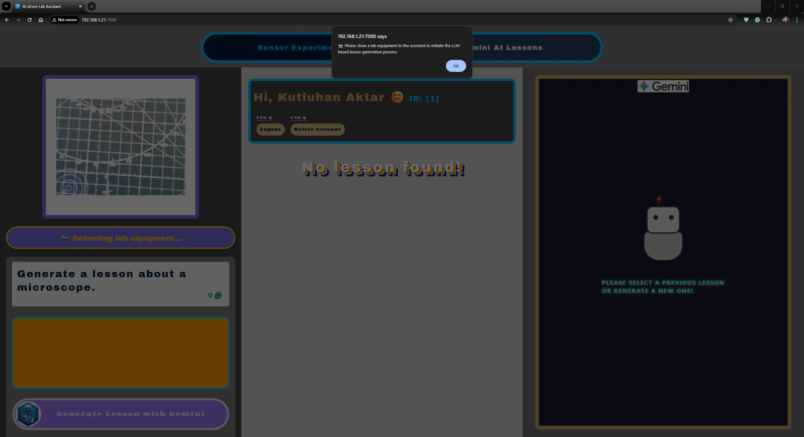
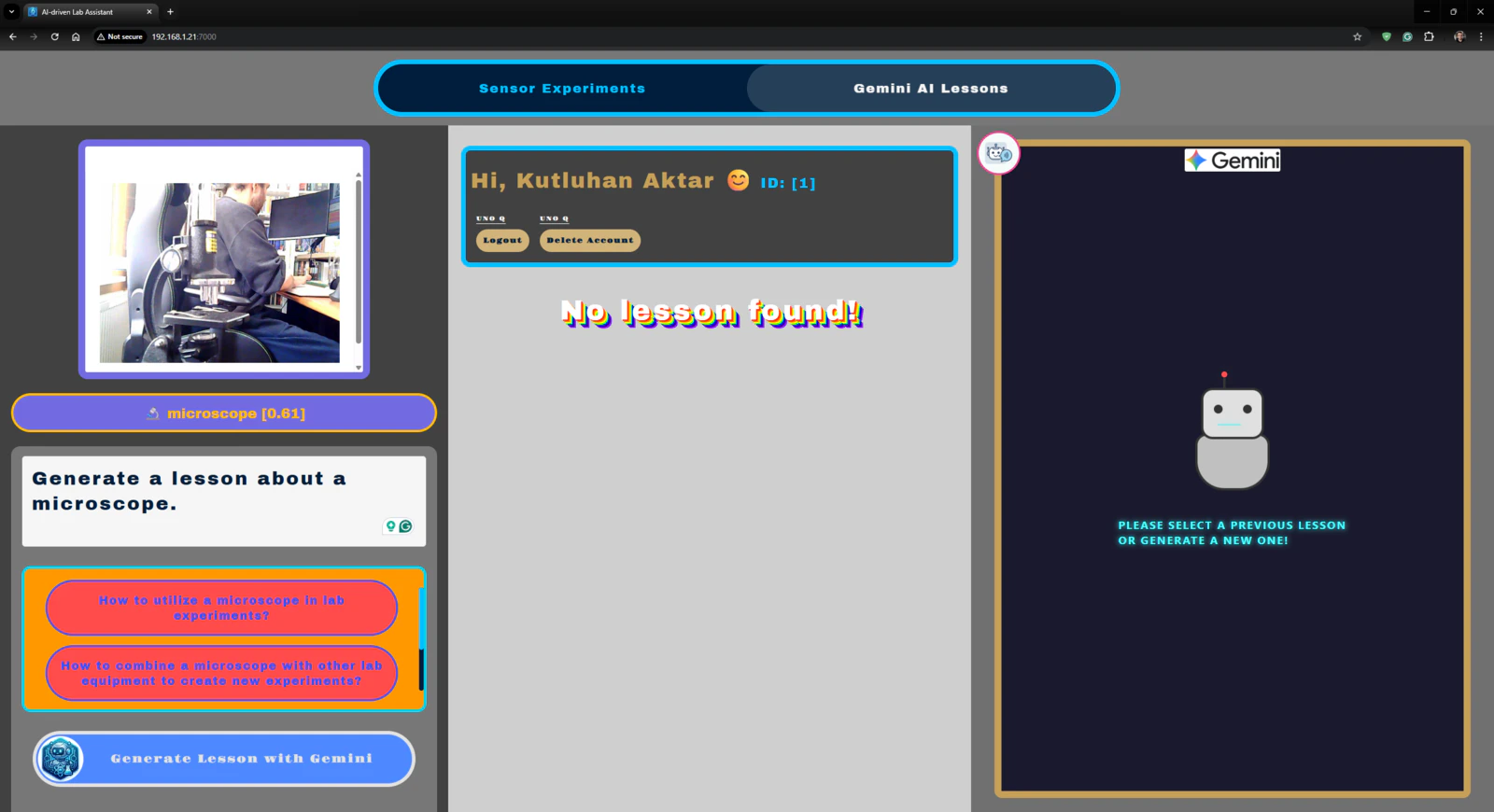
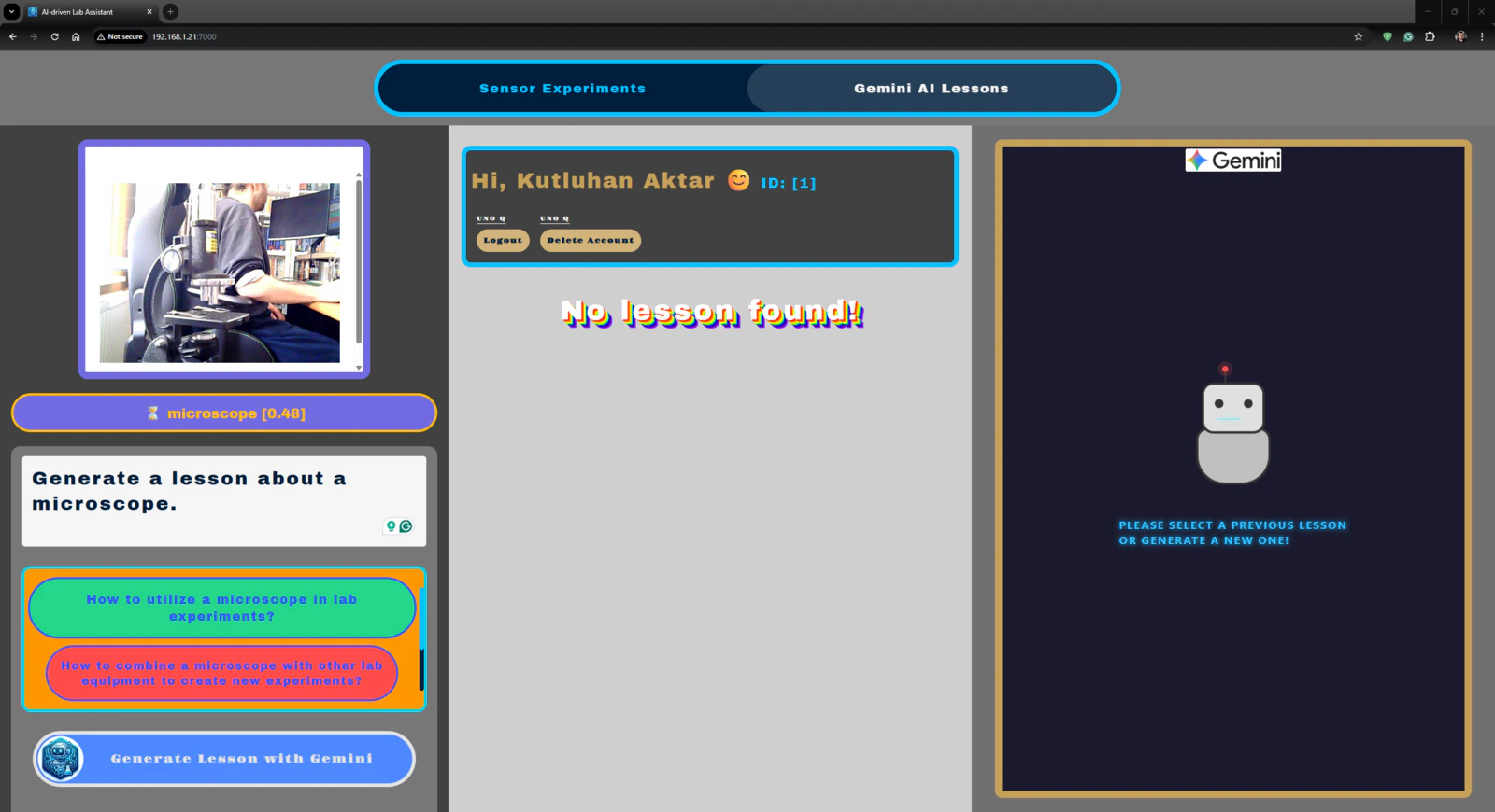
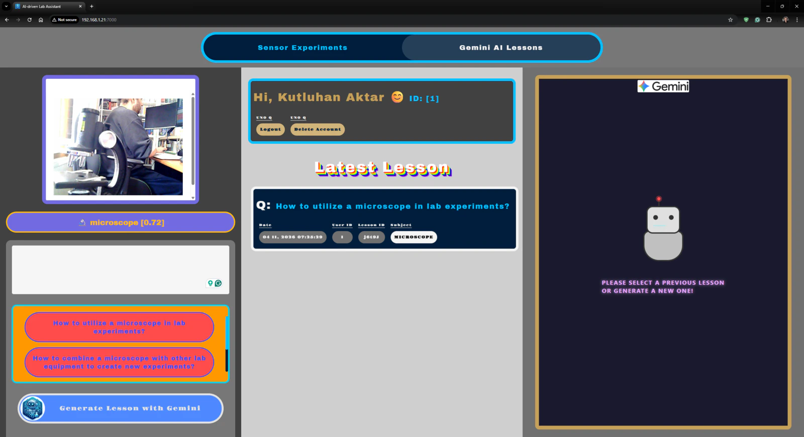
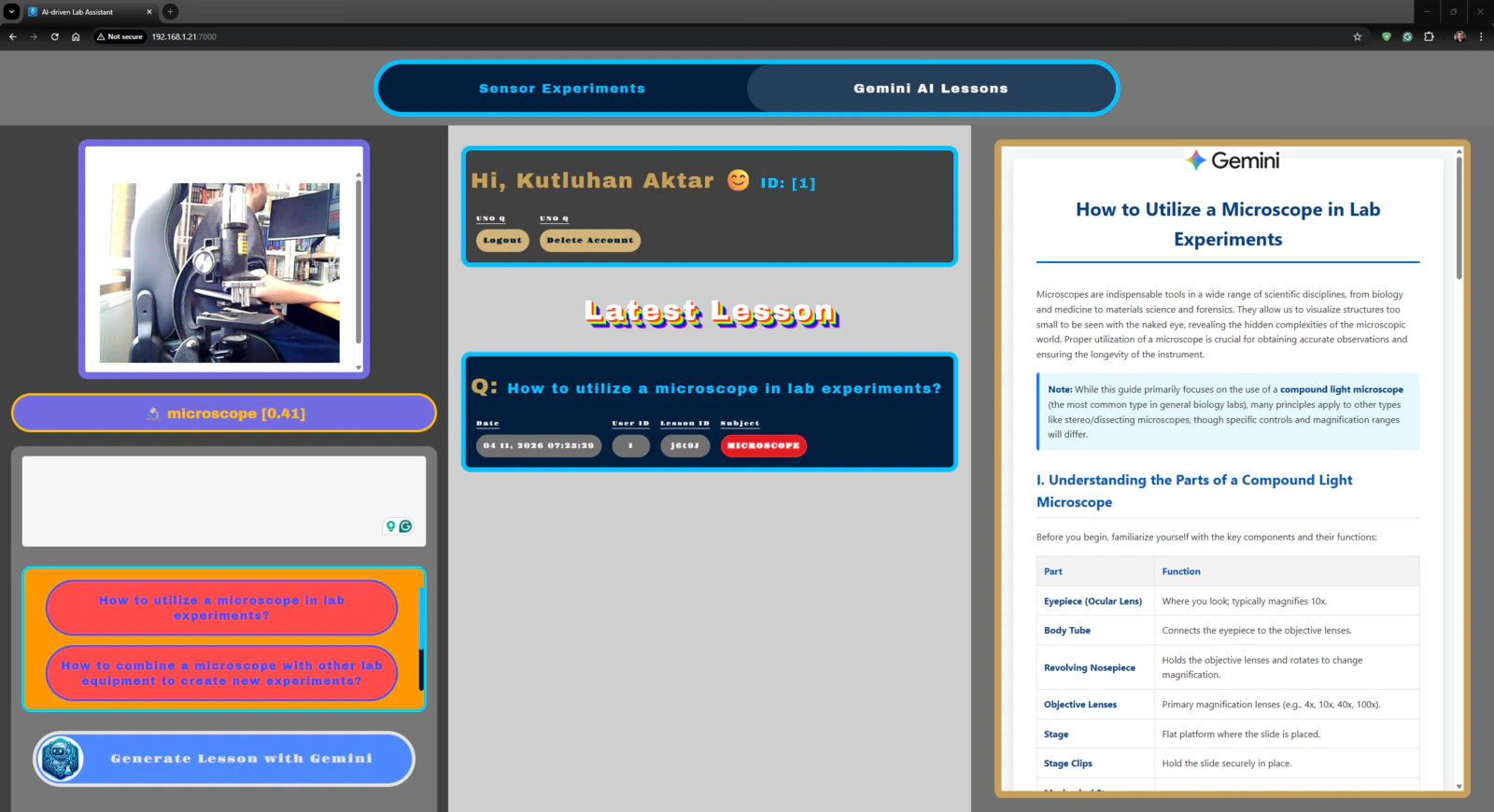
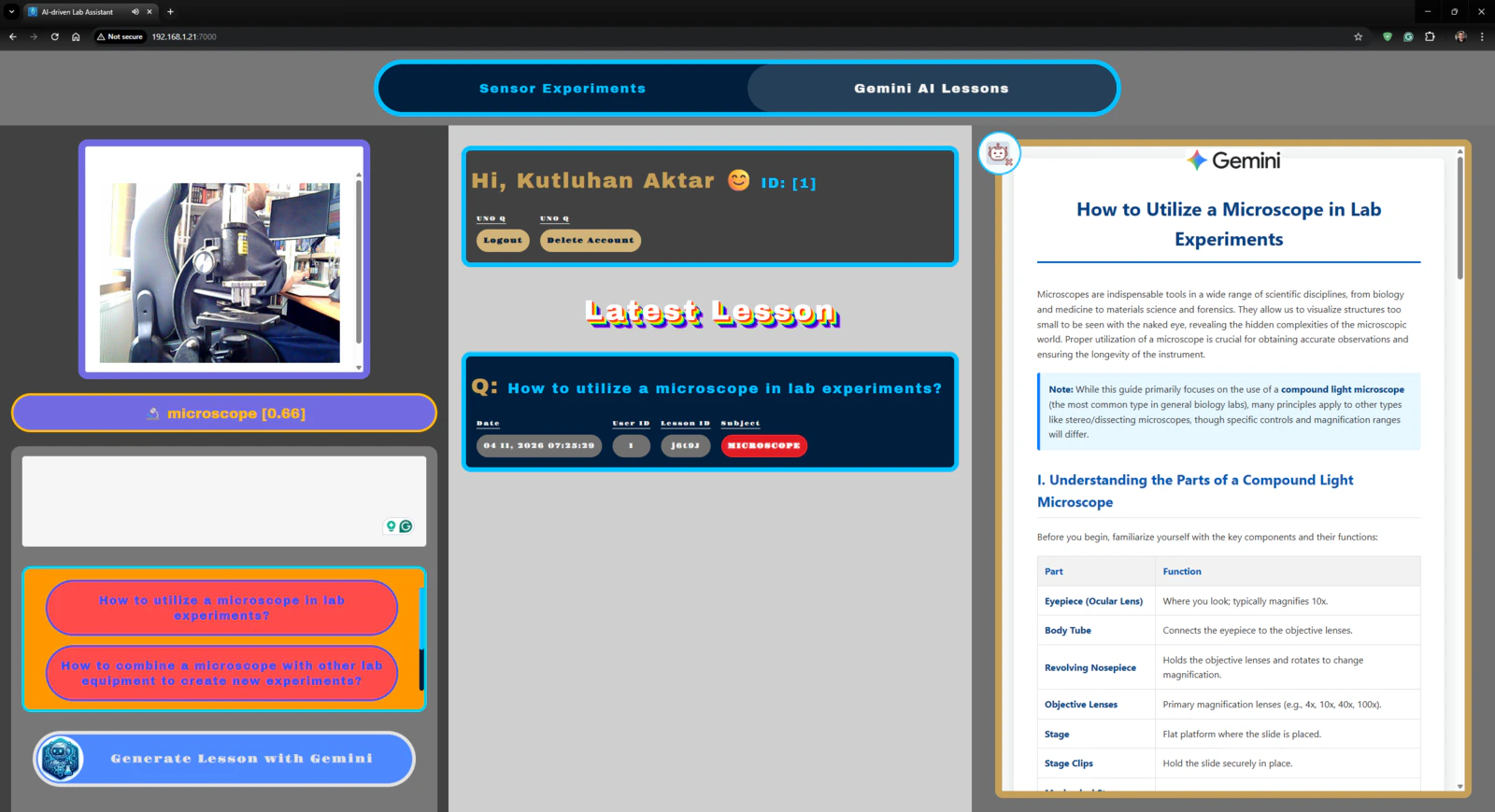
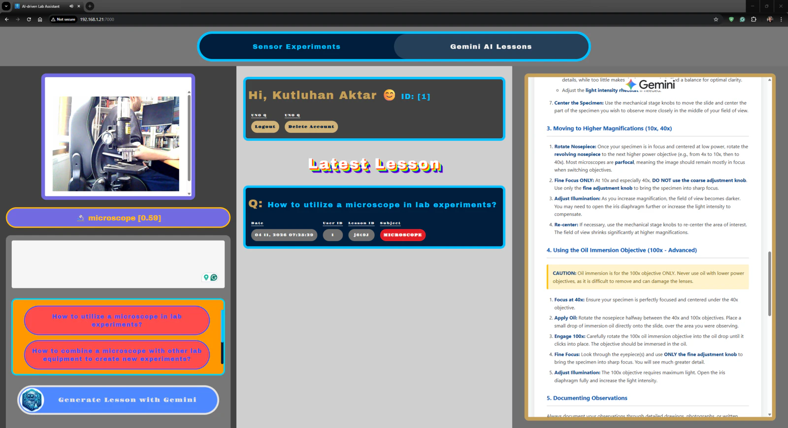
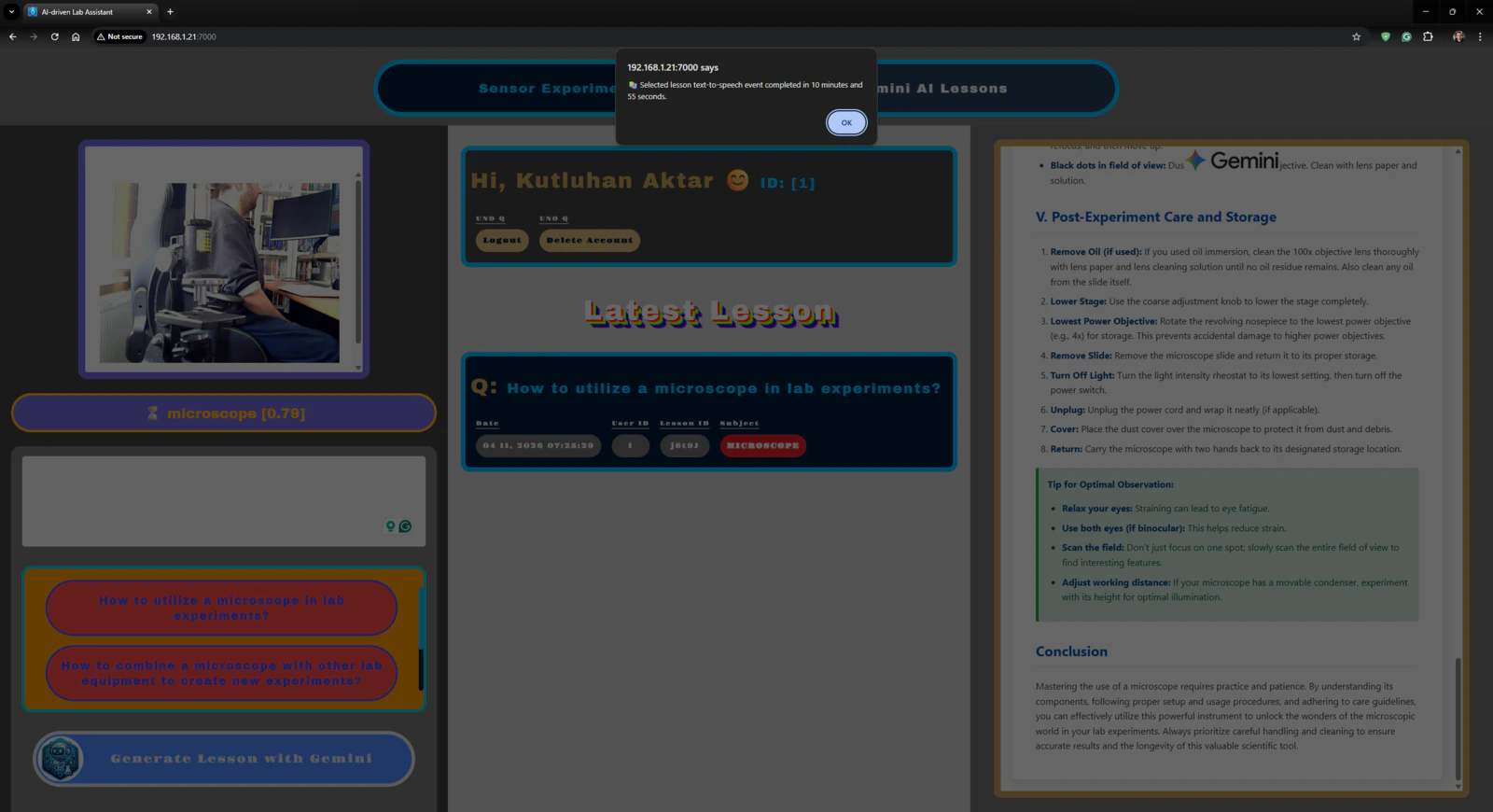
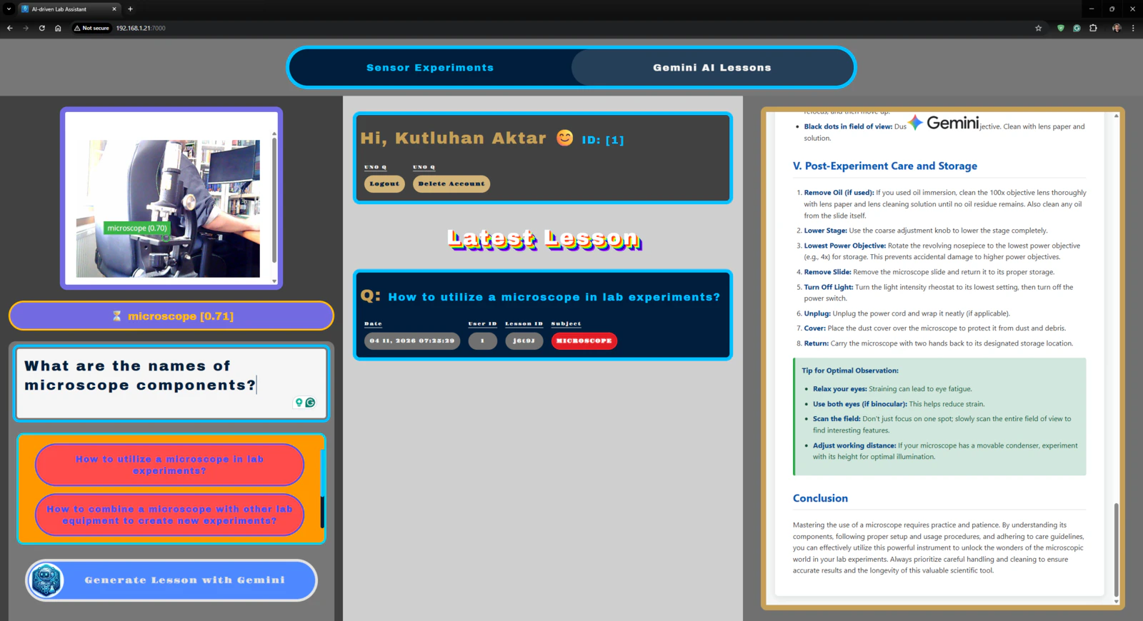
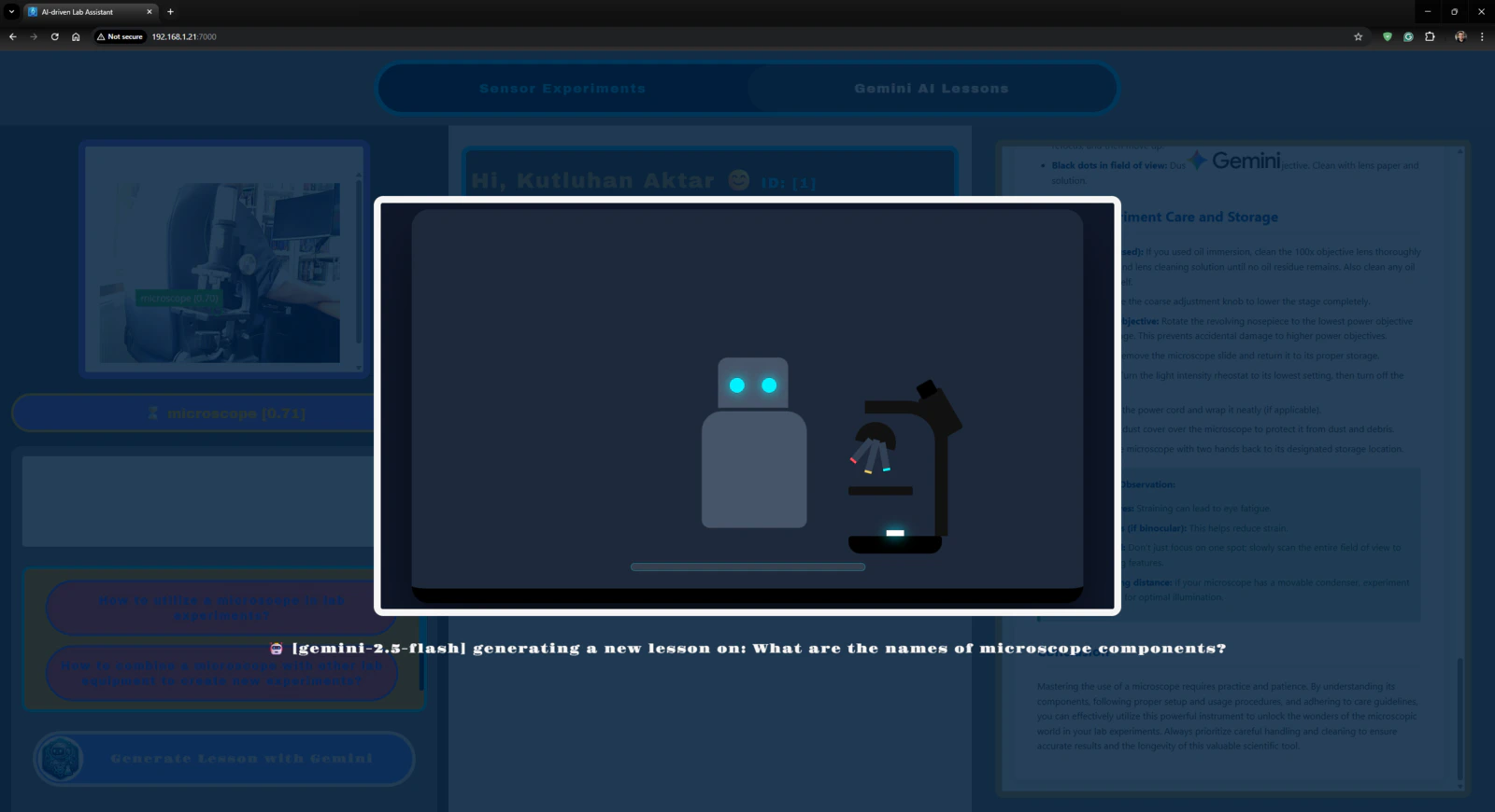
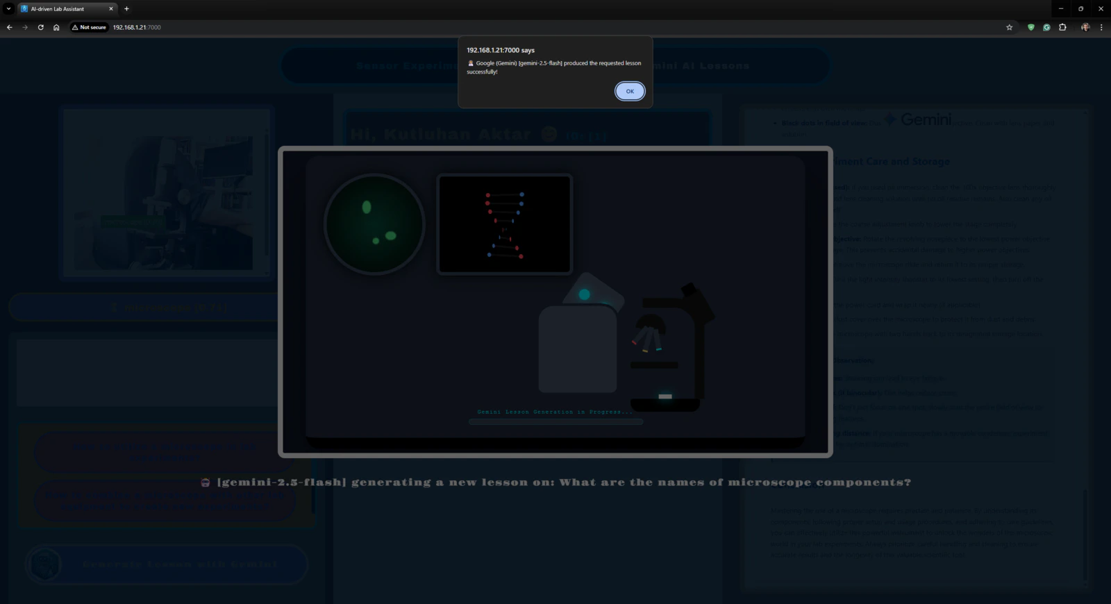
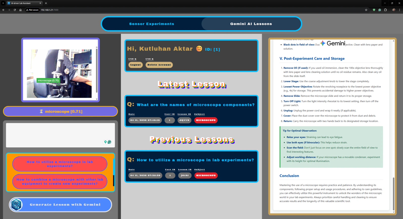
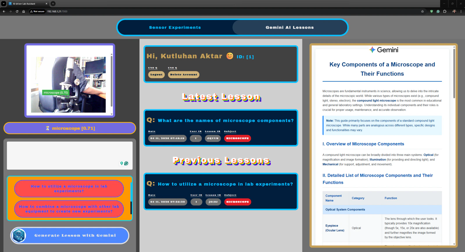
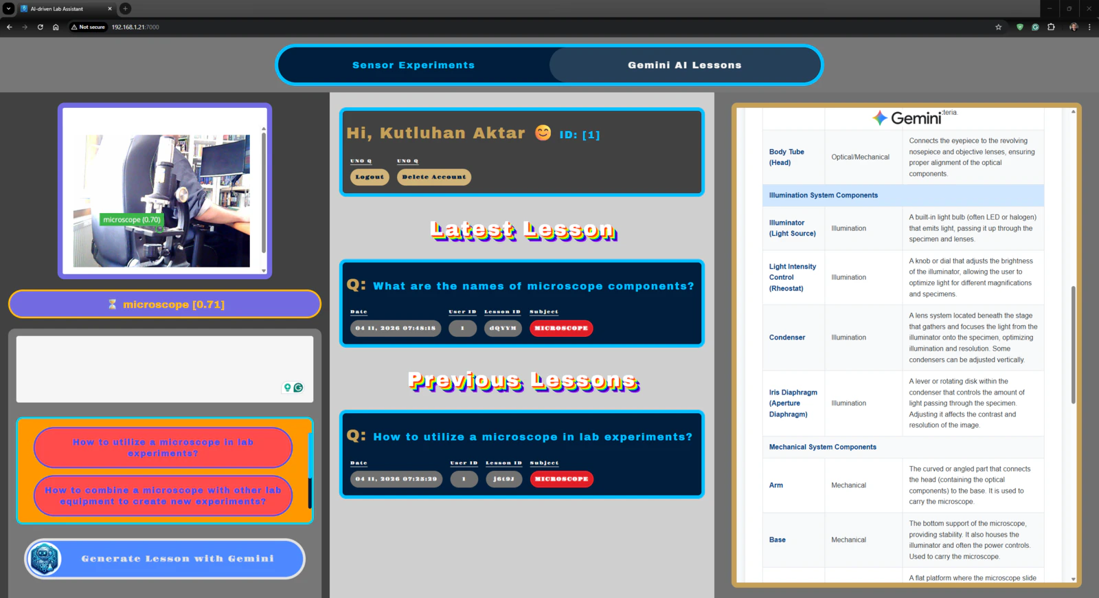
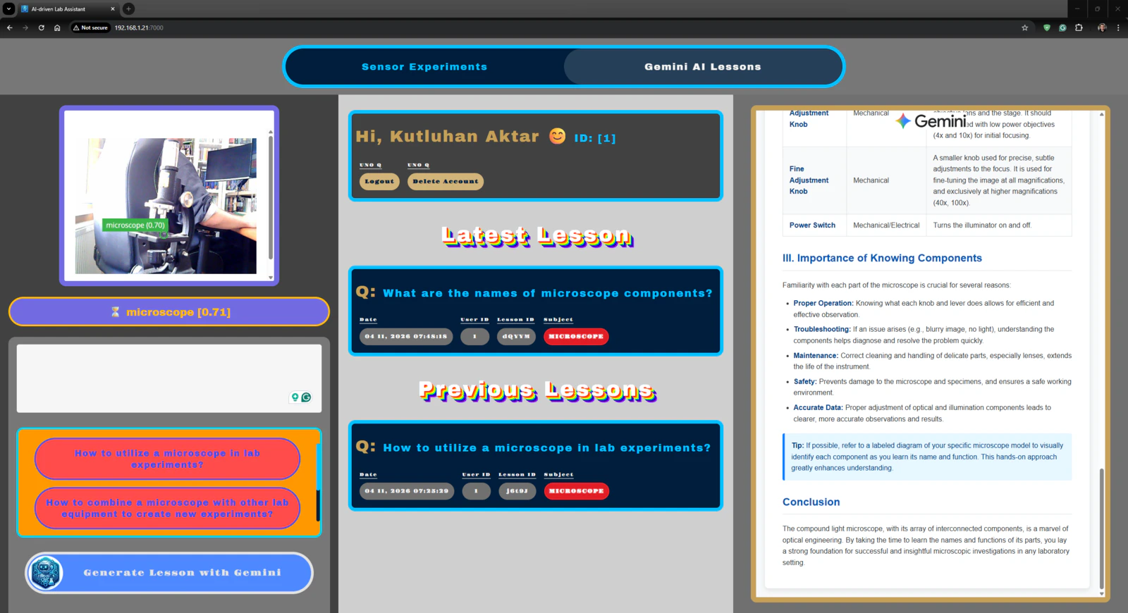
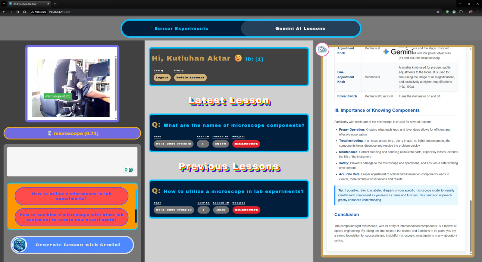
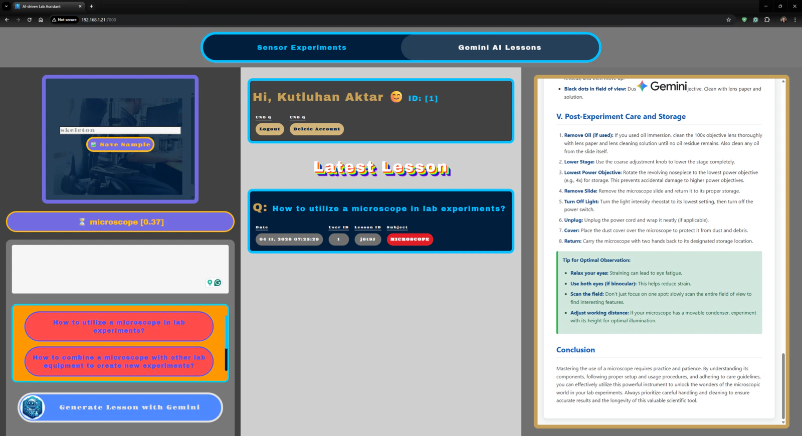
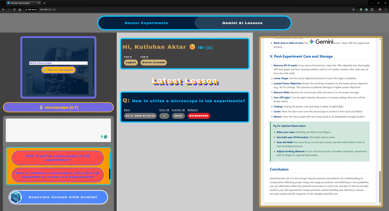
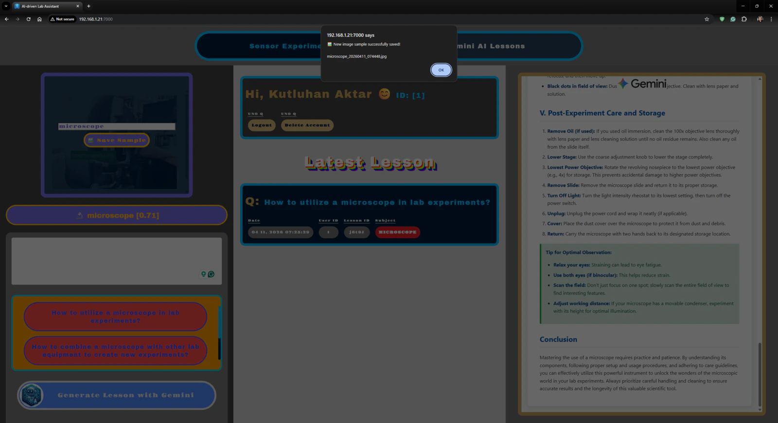
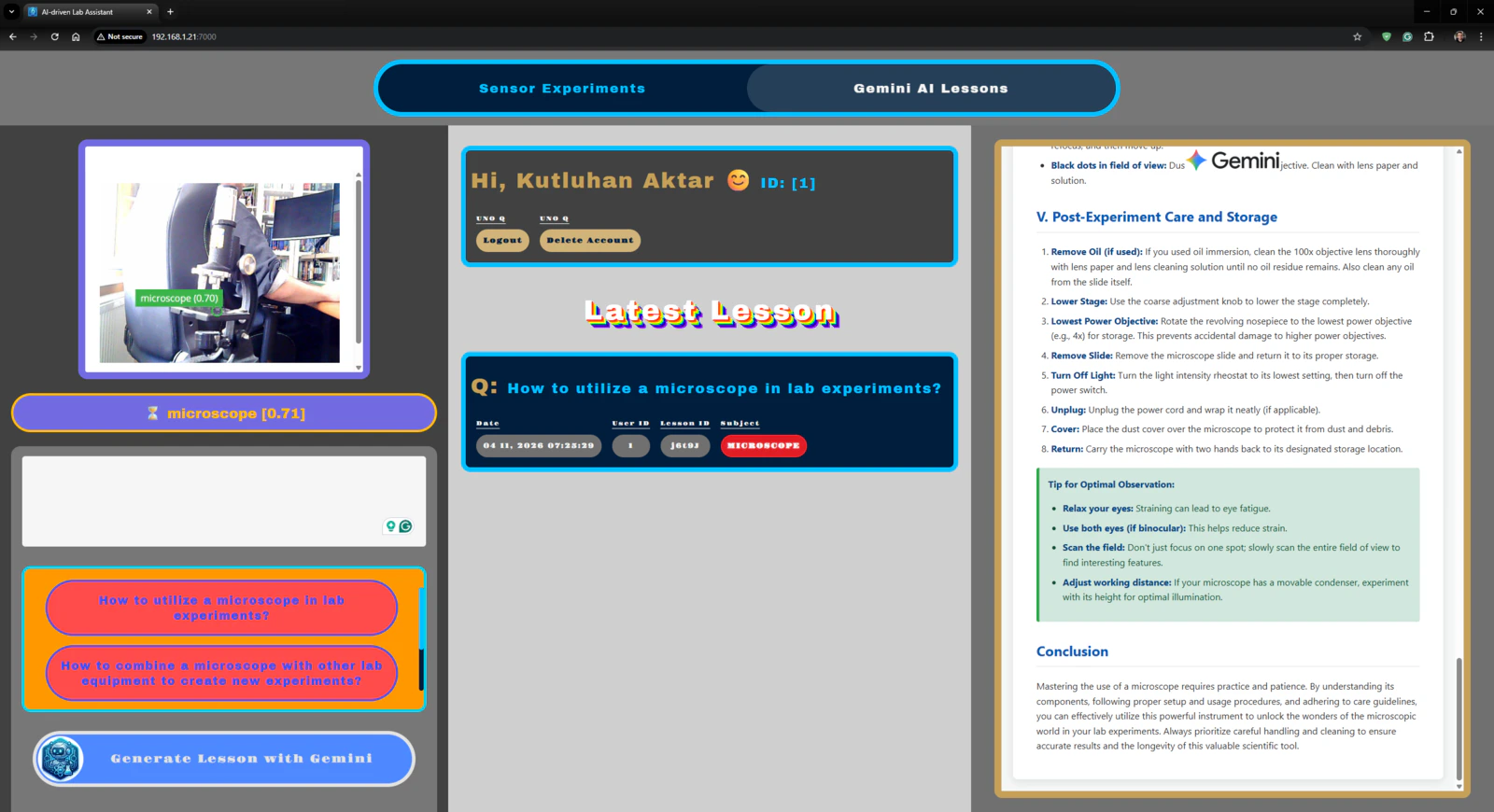
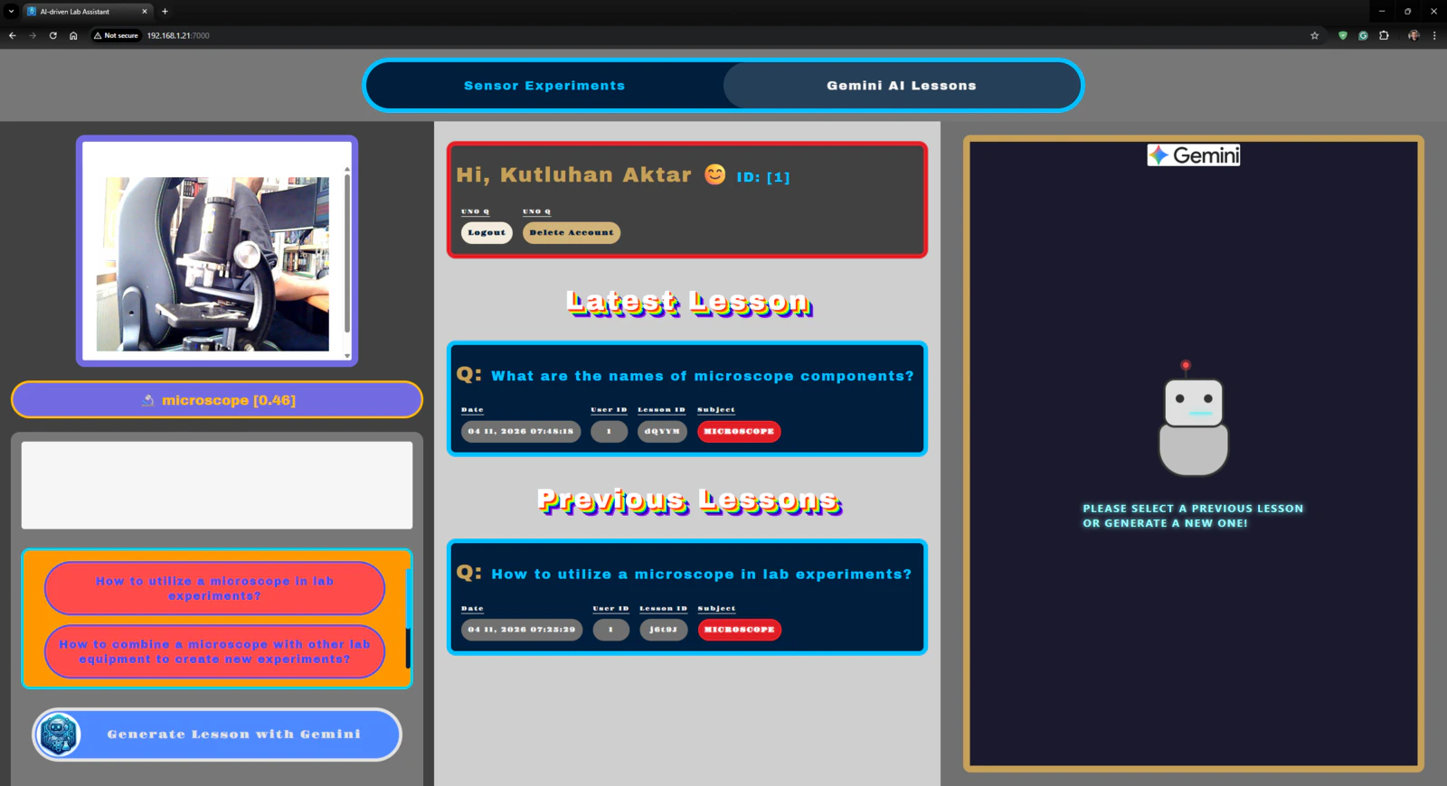
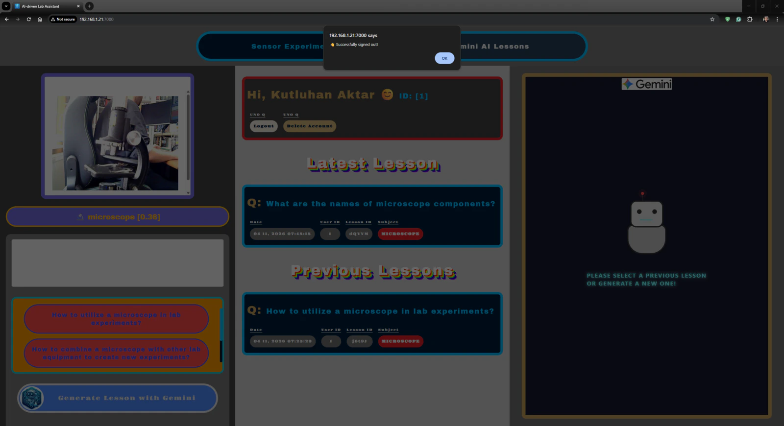
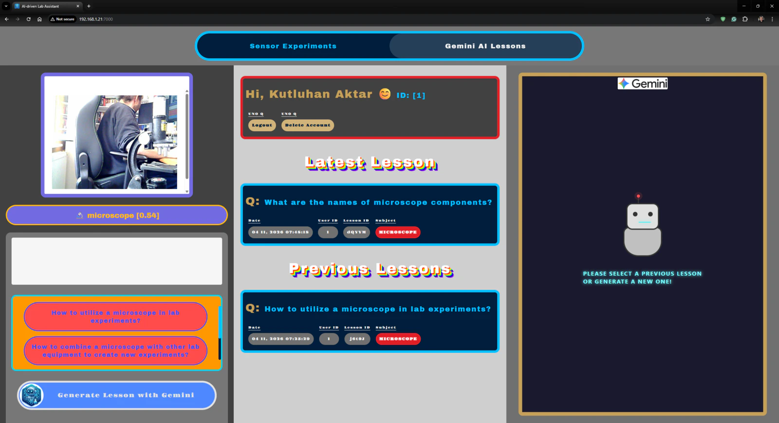
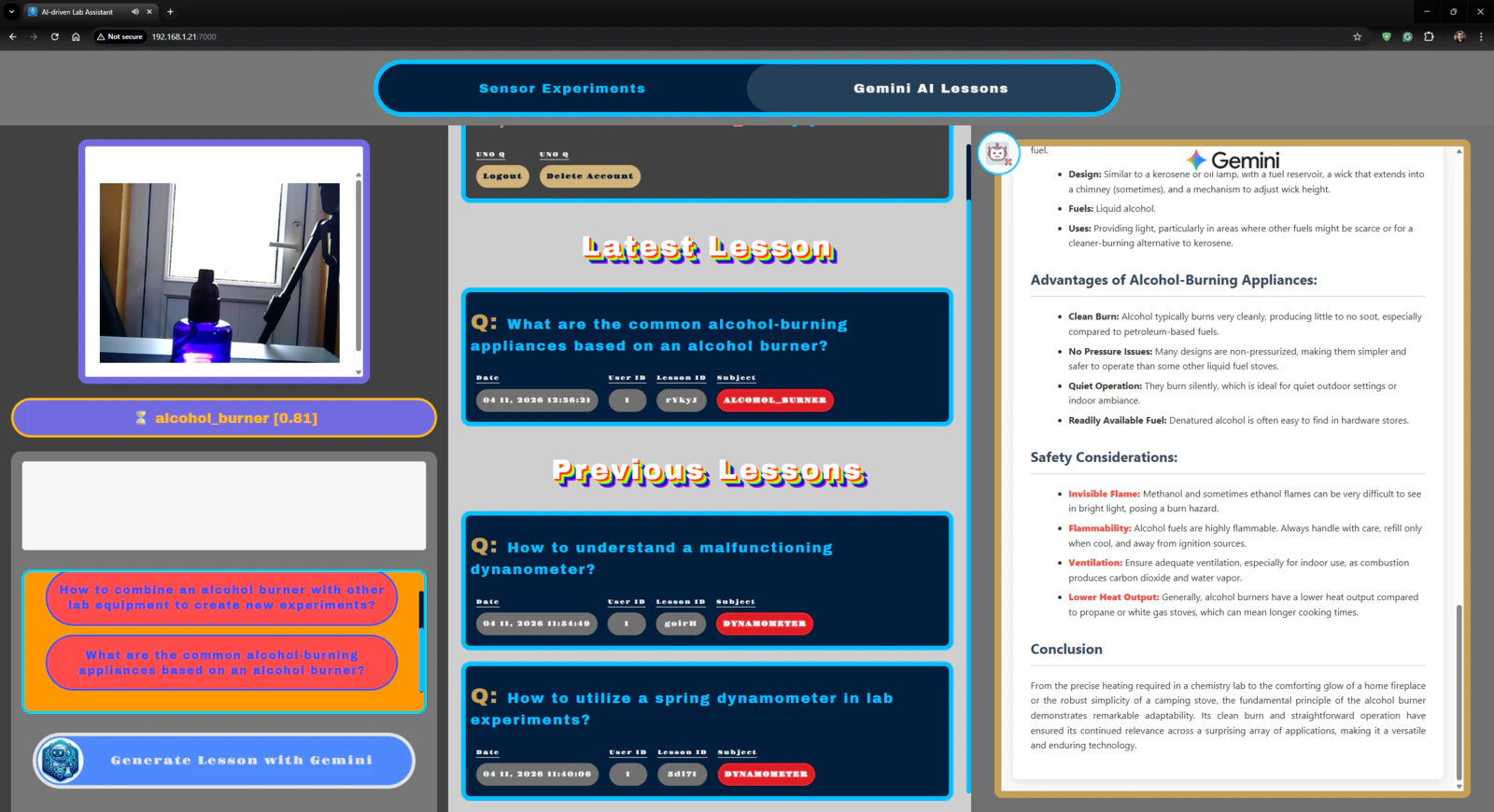
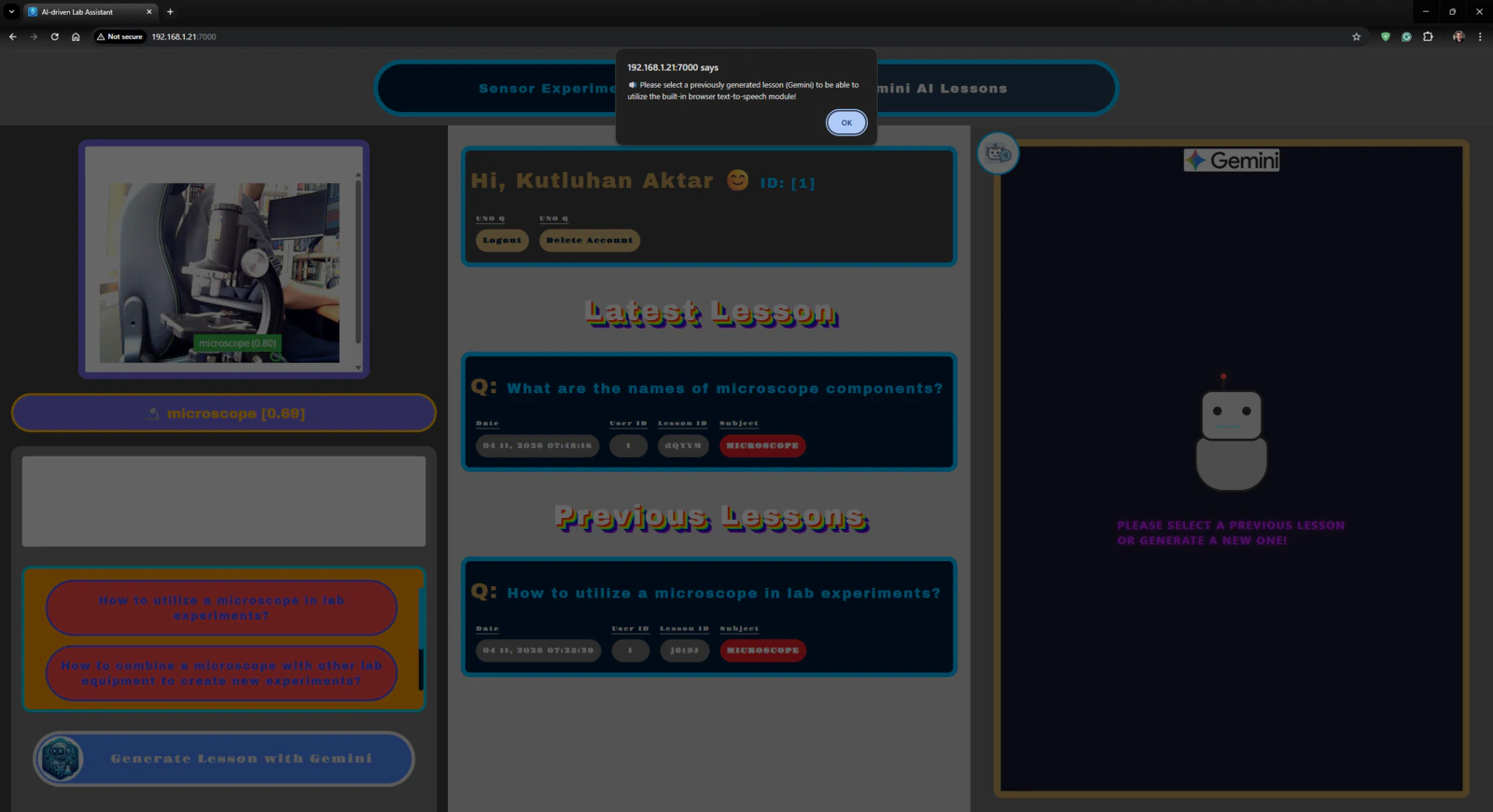
Outcomes: Identifying lab equipment via object detection and generating distinctive AI lessons about them via Google Gemini
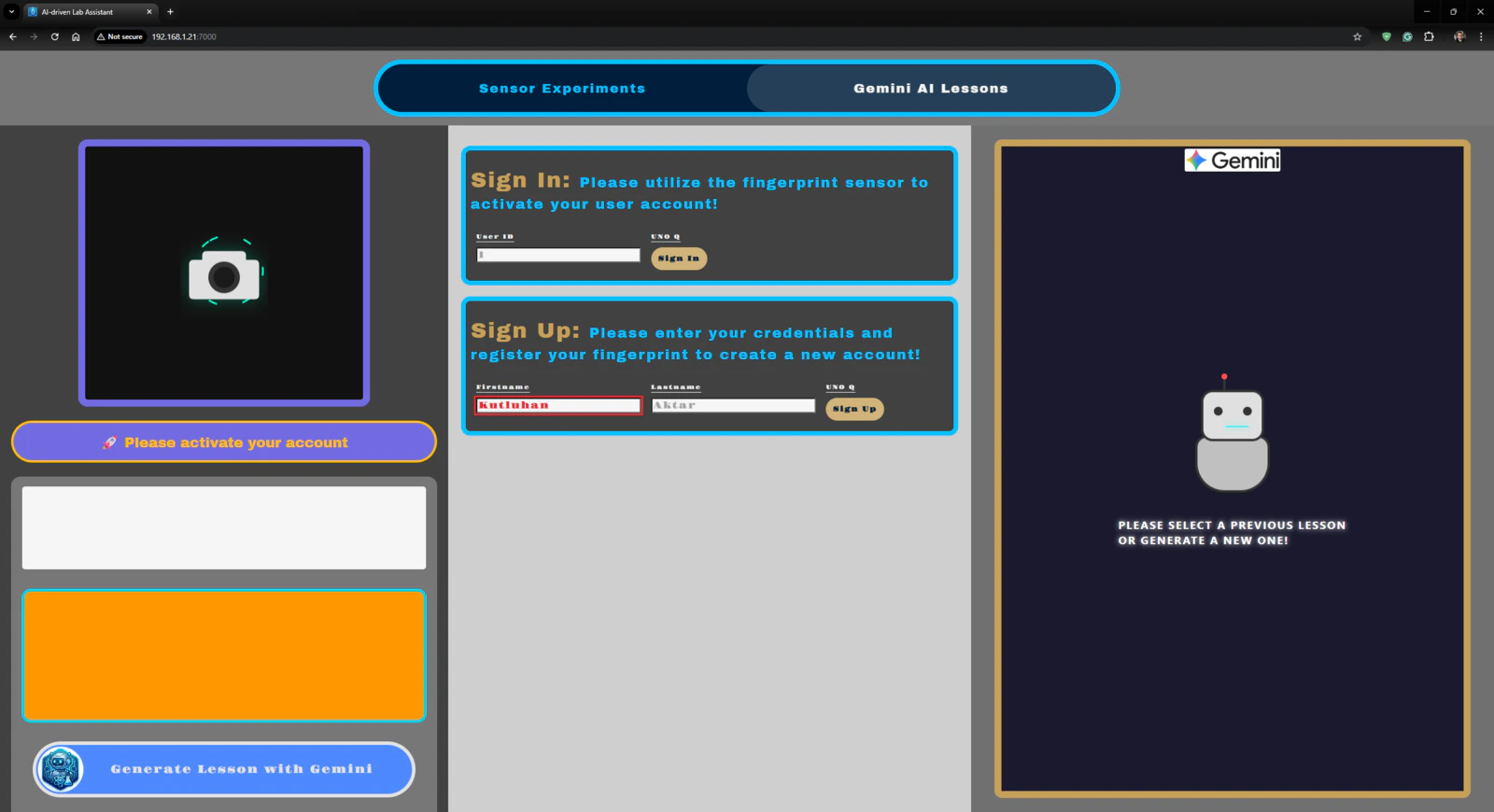
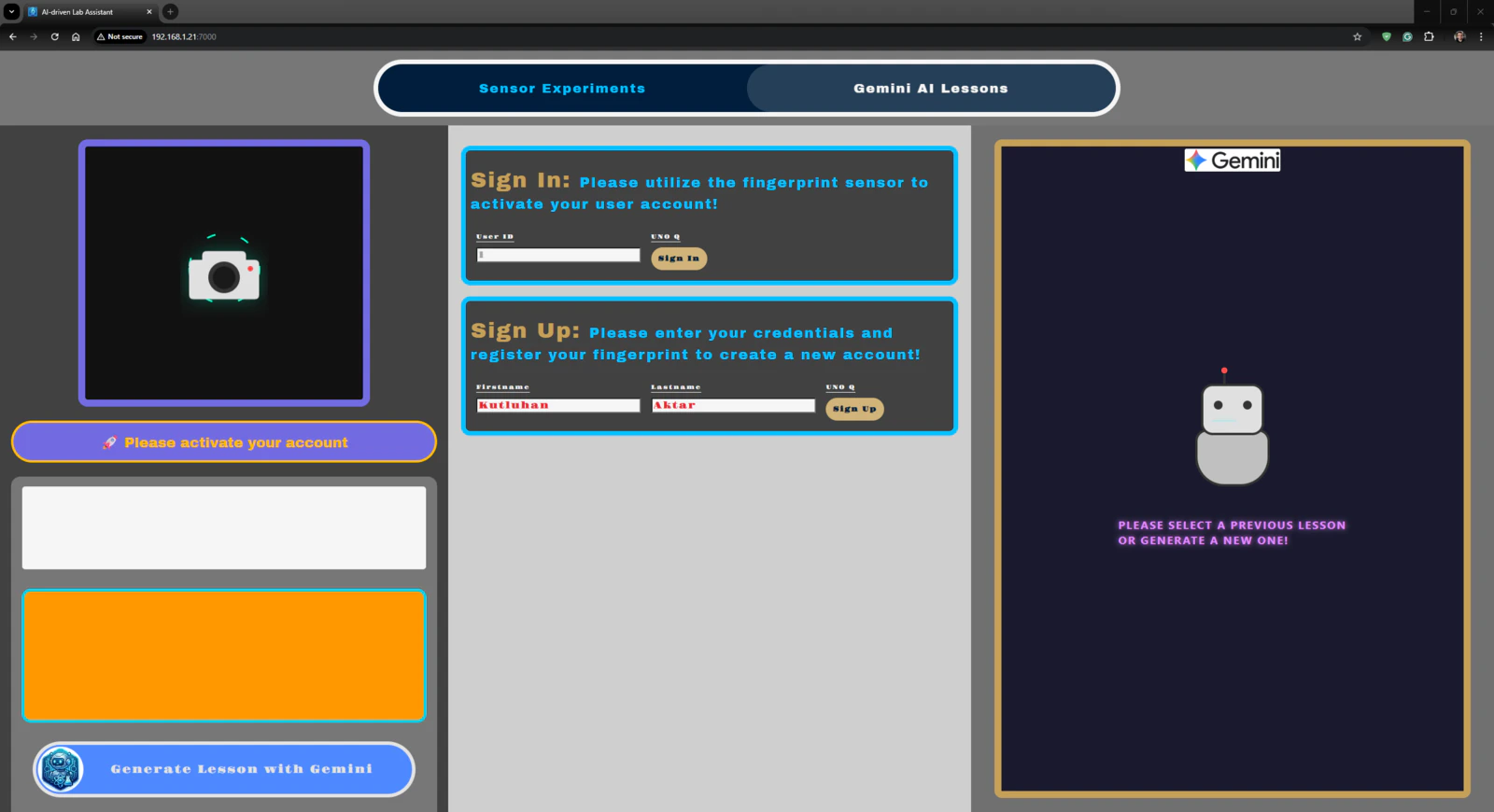
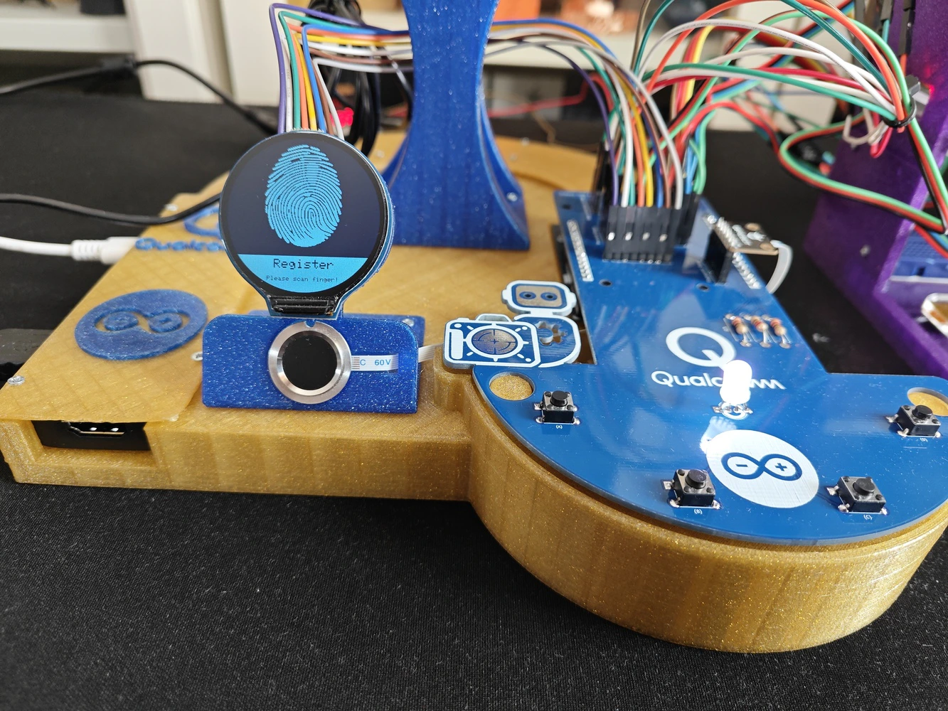
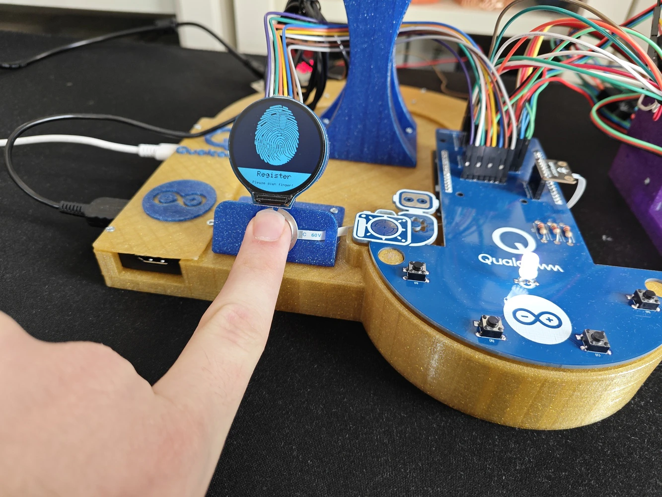
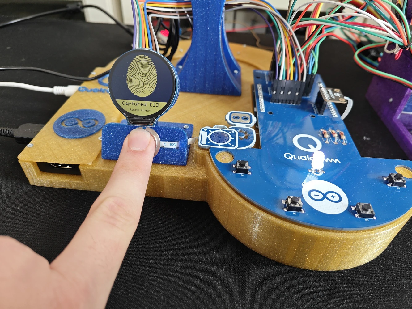
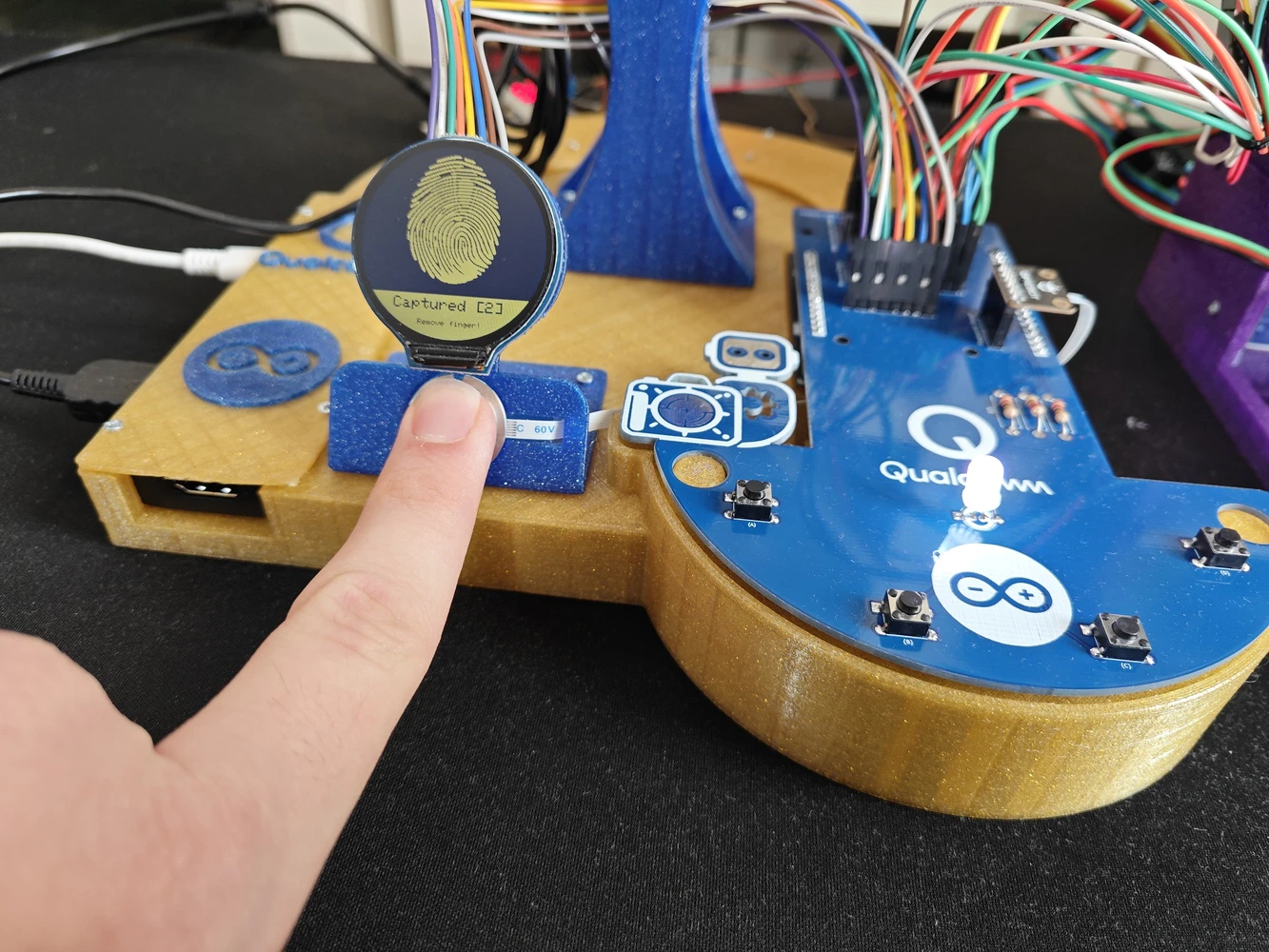
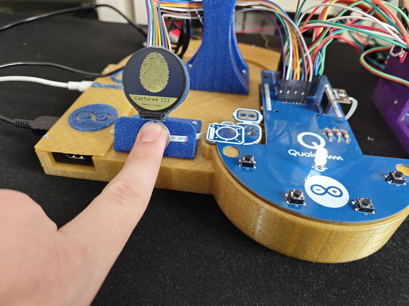
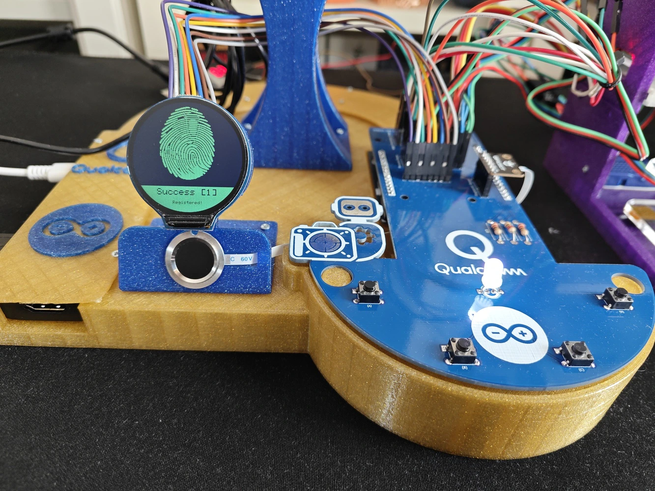
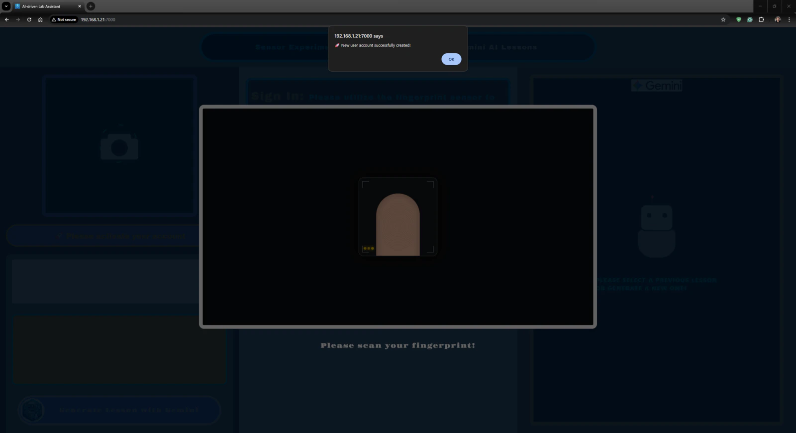
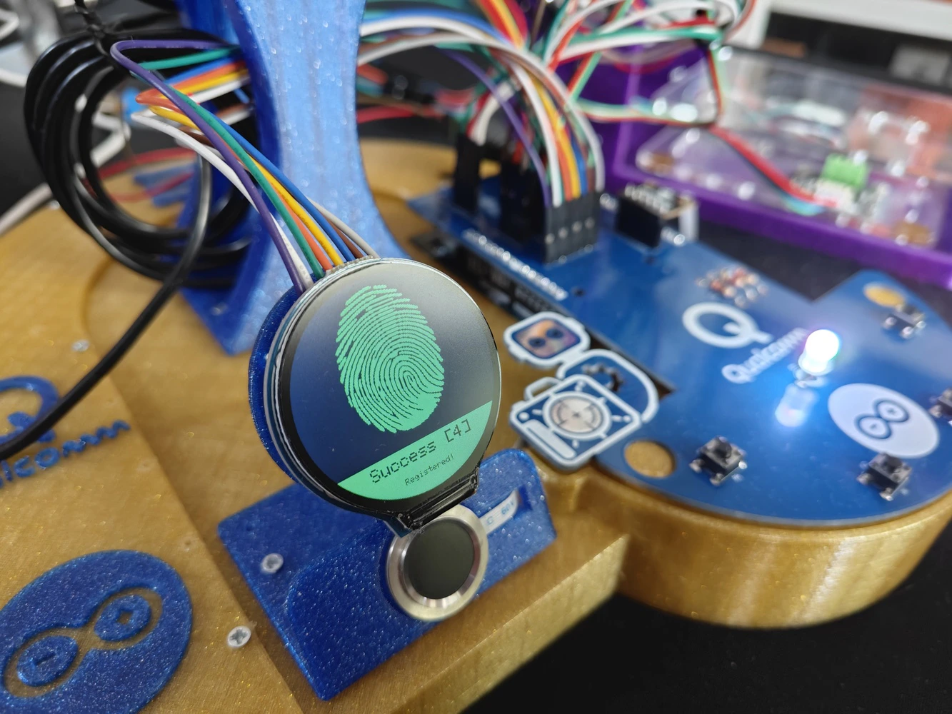
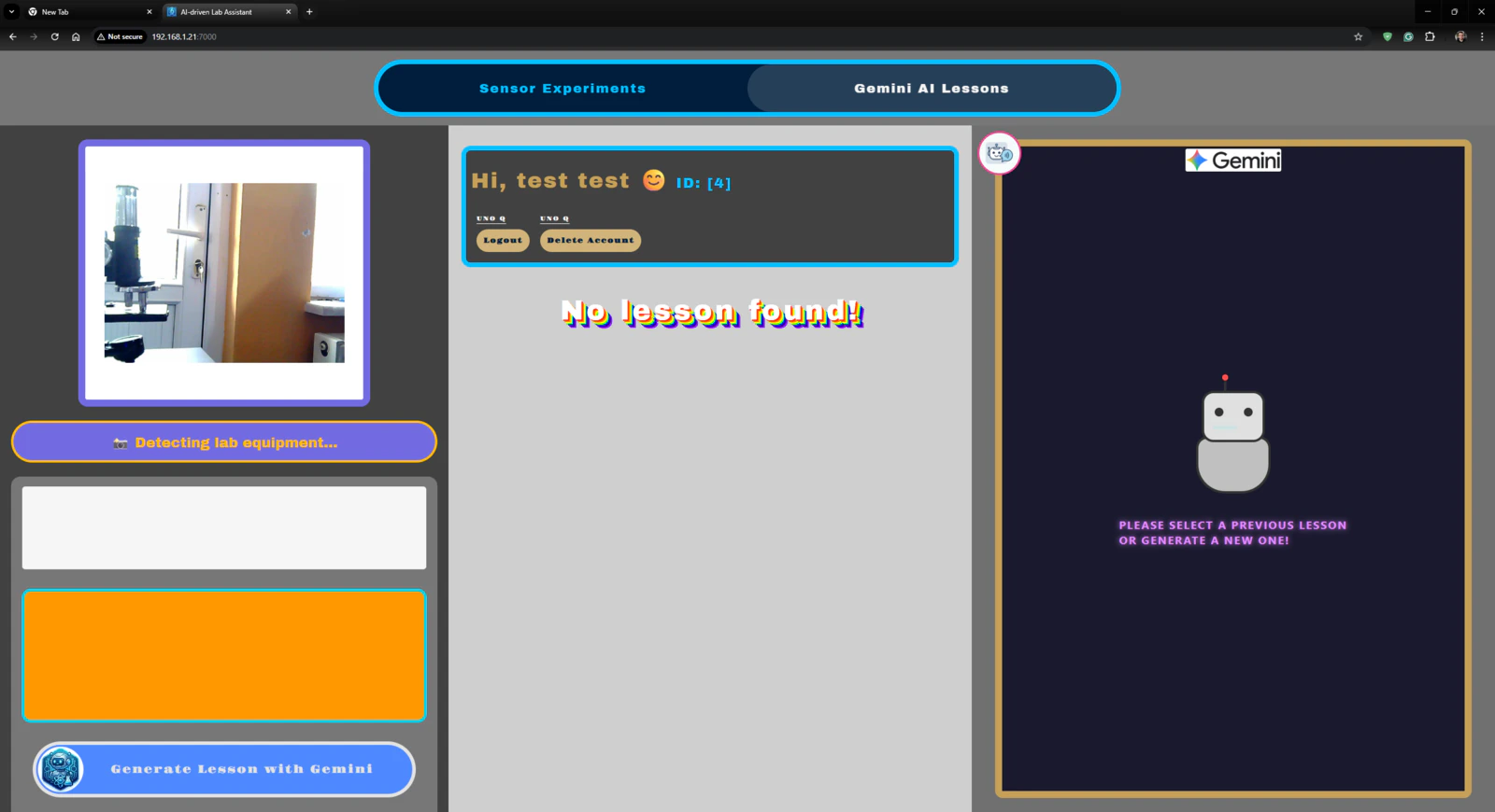
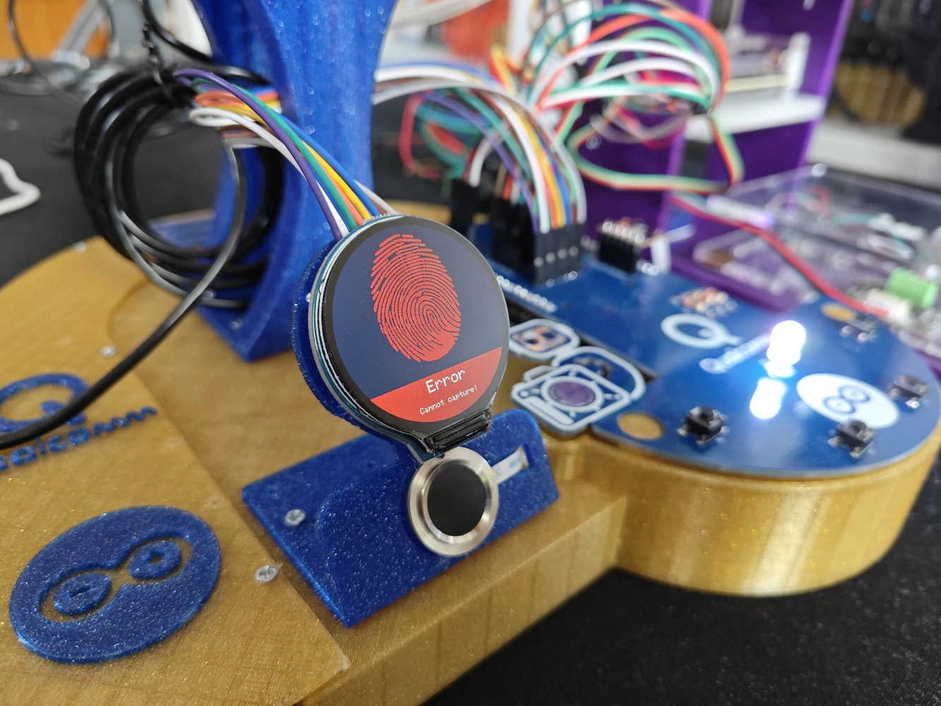
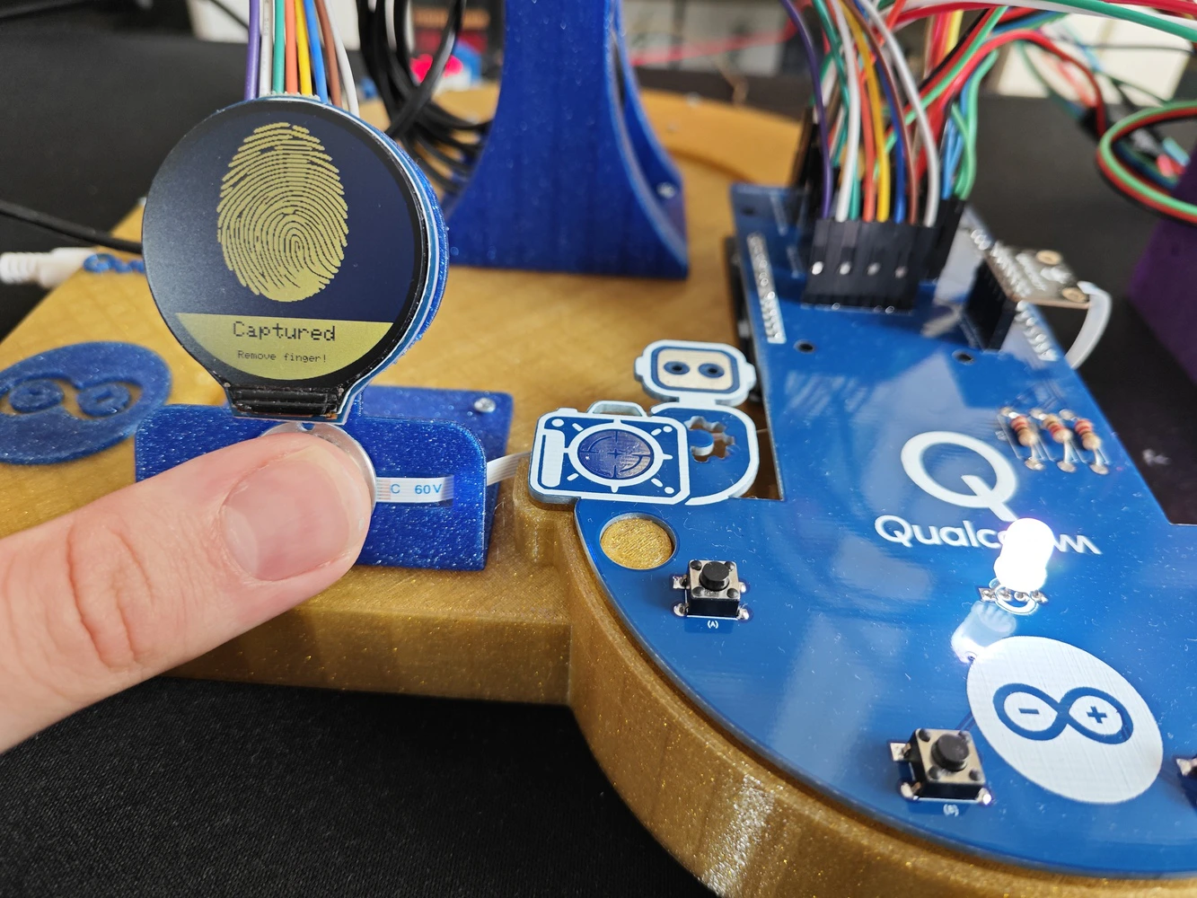
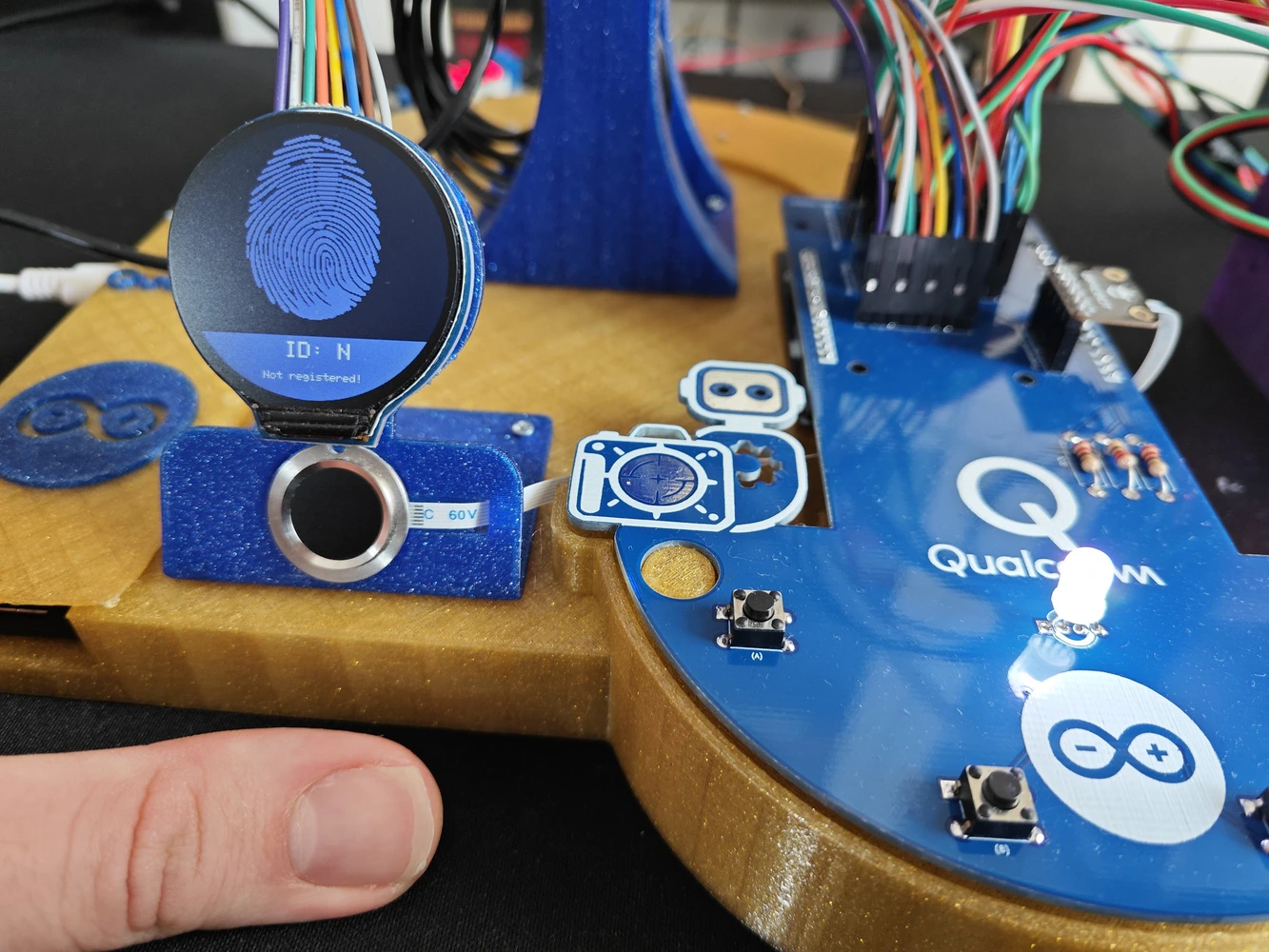
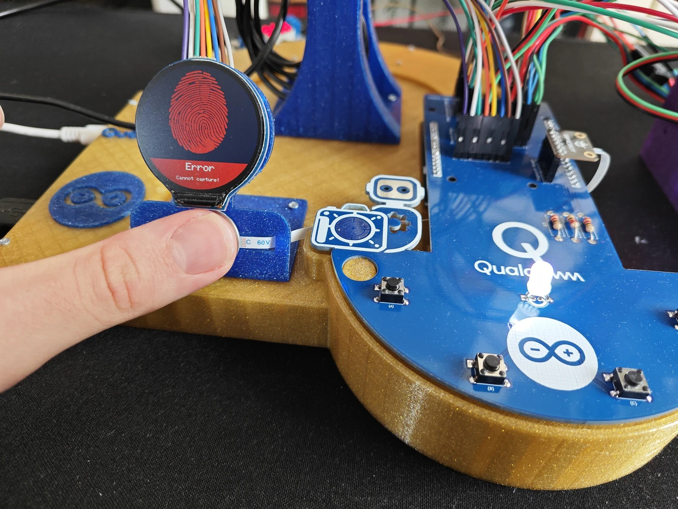
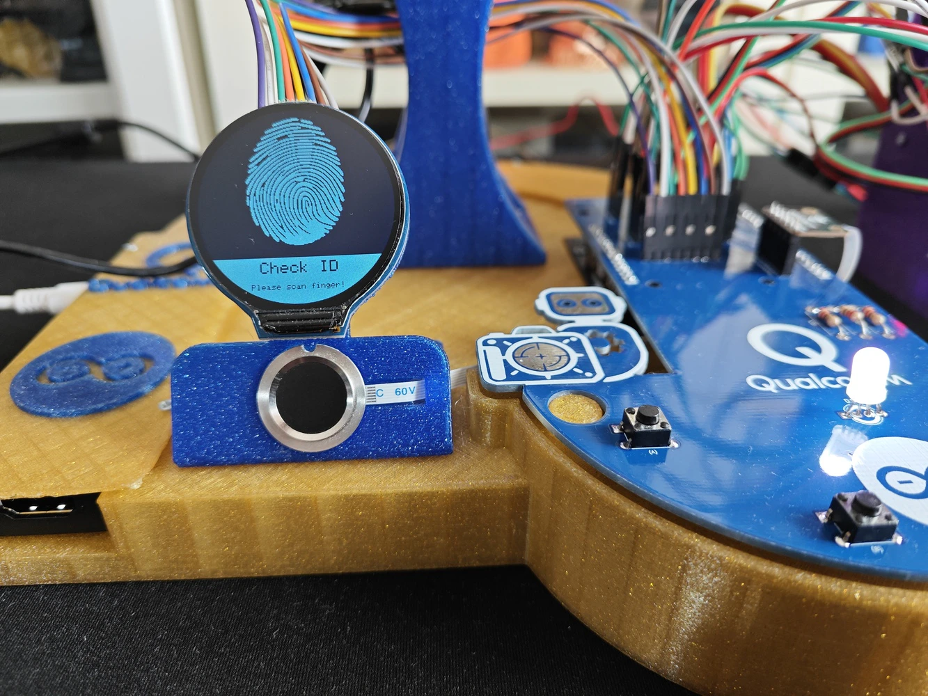
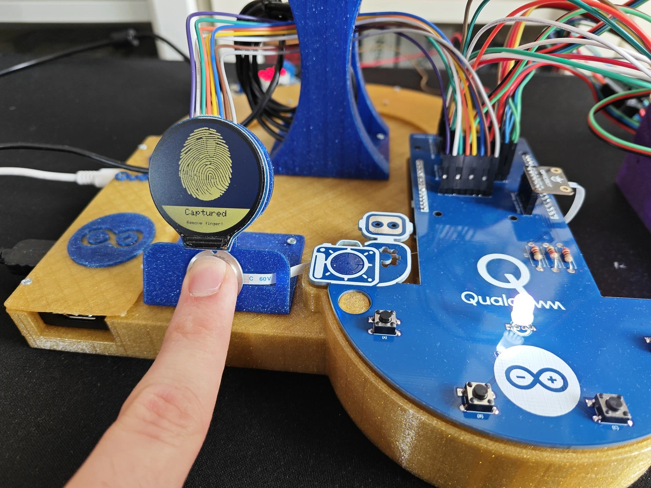
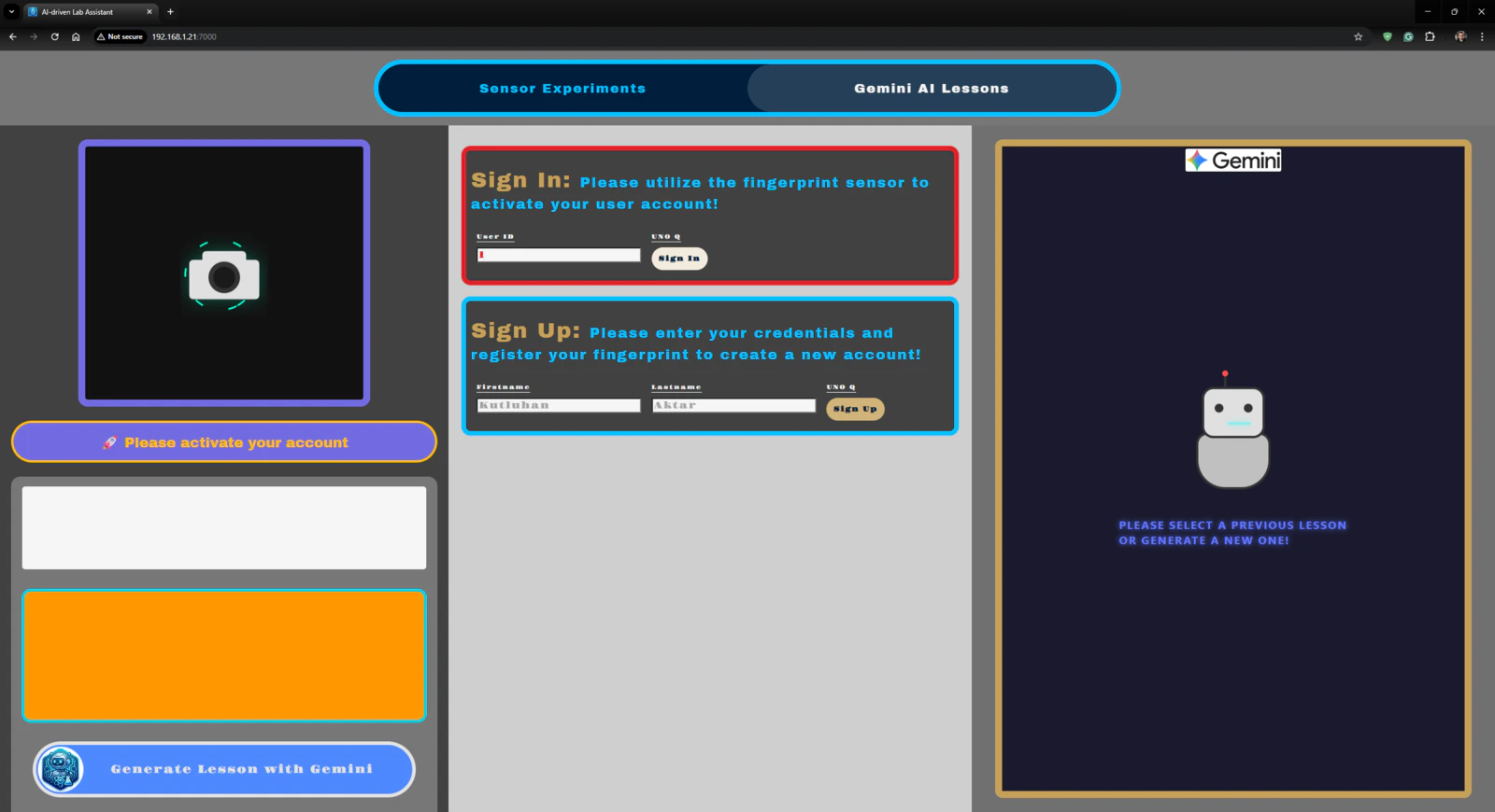
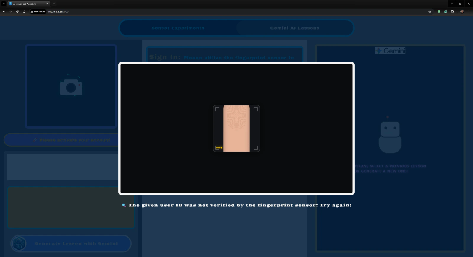
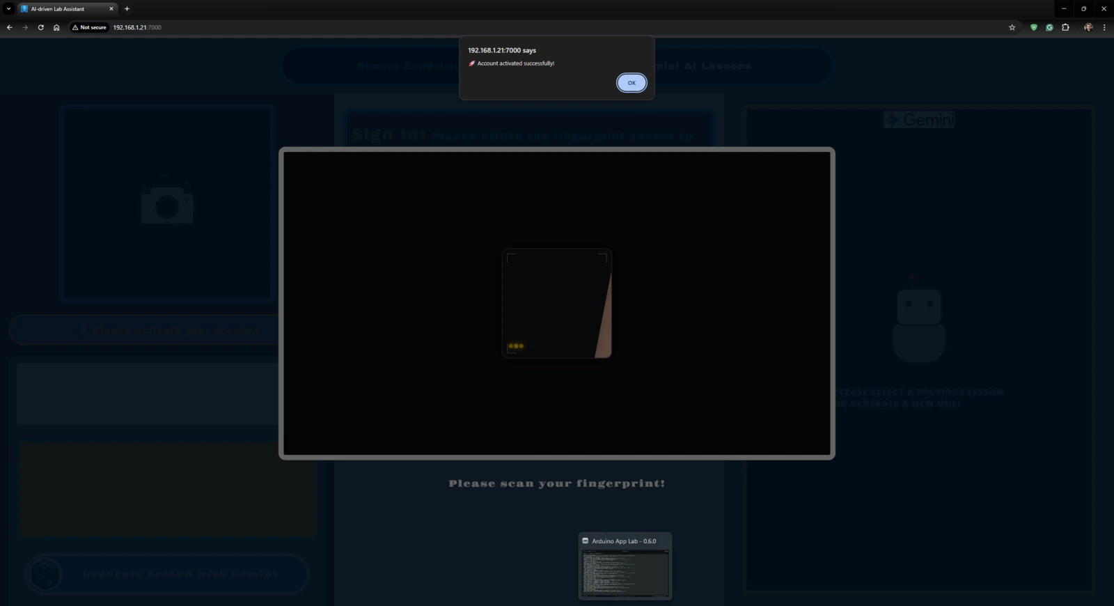
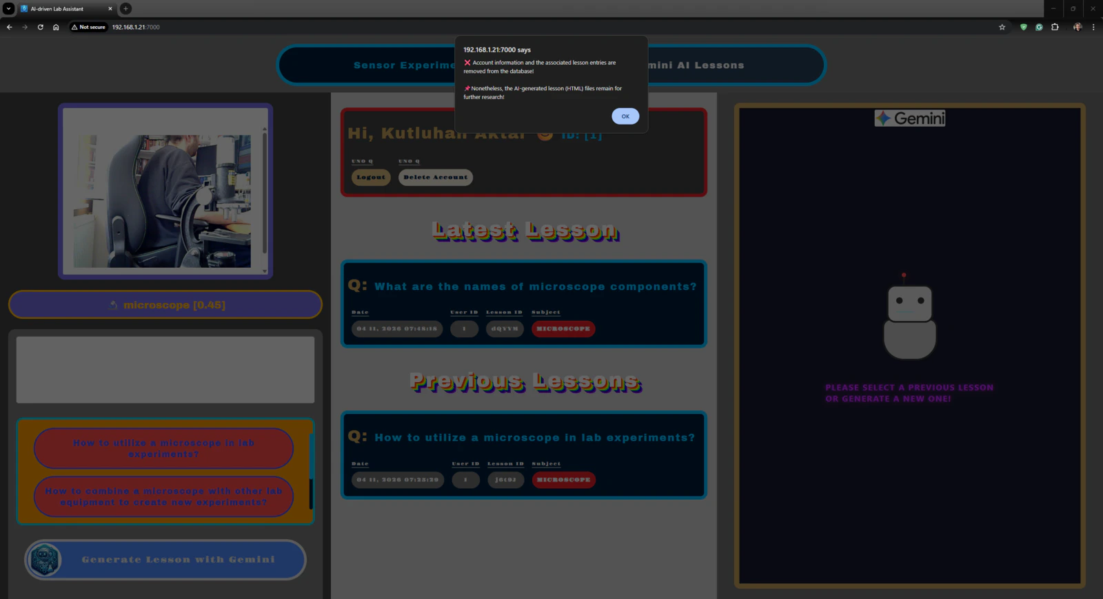
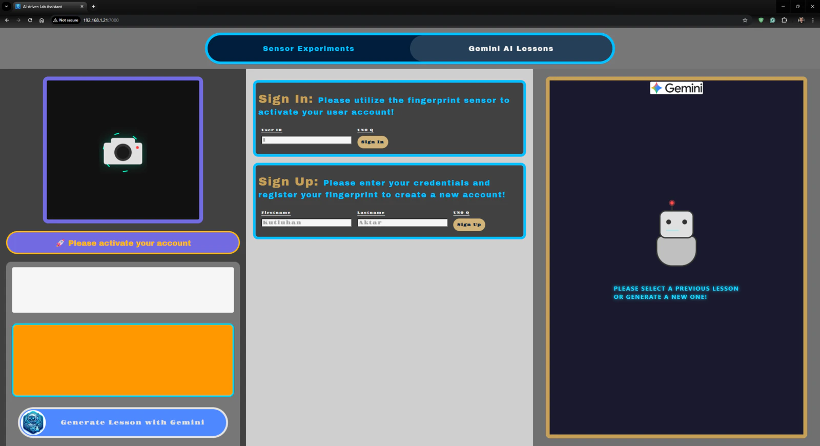
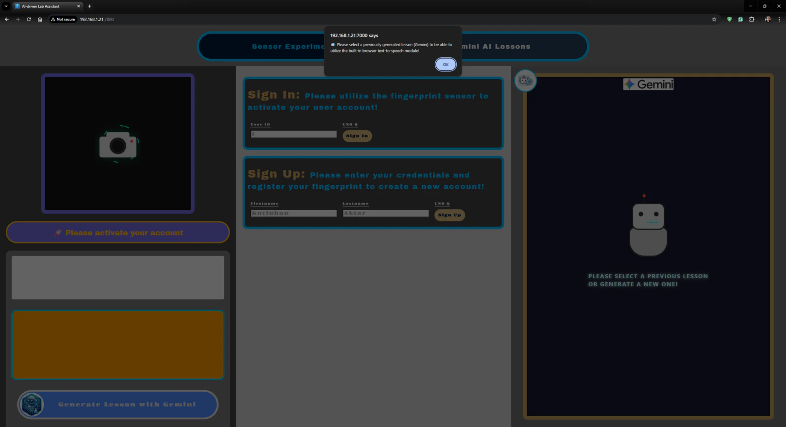
🤖🔬🧬🧫 On the Gemini AI Lessons section, the lab assistant web dashboard enables users to enter their first names and last names to initiate the account creation procedure by fingerprint registration.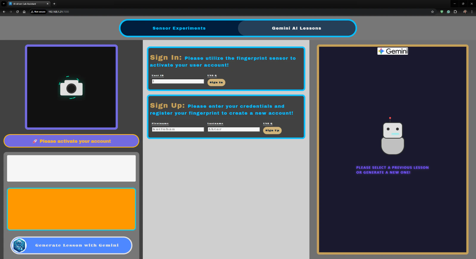


Project GitHub Repository
The project’s GitHub repository provides:- Code files
- The lab assistant App Lab application’s ZIP folder
- PCB design files (Gerber)
- 3D part design files (STL)
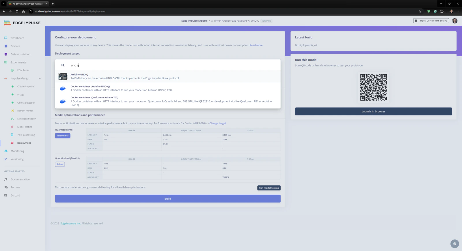
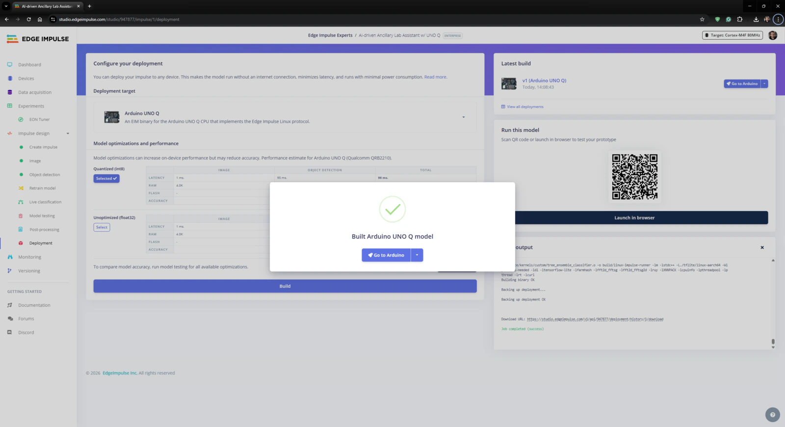
- Edge Impulse FOMO object detection model (EIM binary for UNO Q)