Introduction
Pumps are critical equipment in every industrial operation. Pumps move liquids like beverages, dyes, and chemicals around production lines. They’re also part of ancillary systems like hydraulics, lubrication, machine cooling, HVAC, and wastewater; all necessary to keep machines working, plant environments safe, and temperatures steady. Whatever pumps are doing, we want to keep them healthy! For years, manufacturers have been practicing a preventive maintenance approach for industrial pumps. However, this method of monitoring pump health has previously been a potentially time-intensive and costly task due to manual inspections of each piece of equipment. When equipment is large in number and placed in less-accessible areas, the probability of failed equipment going unnoticed for an extended period of time is relatively high.The Challenge
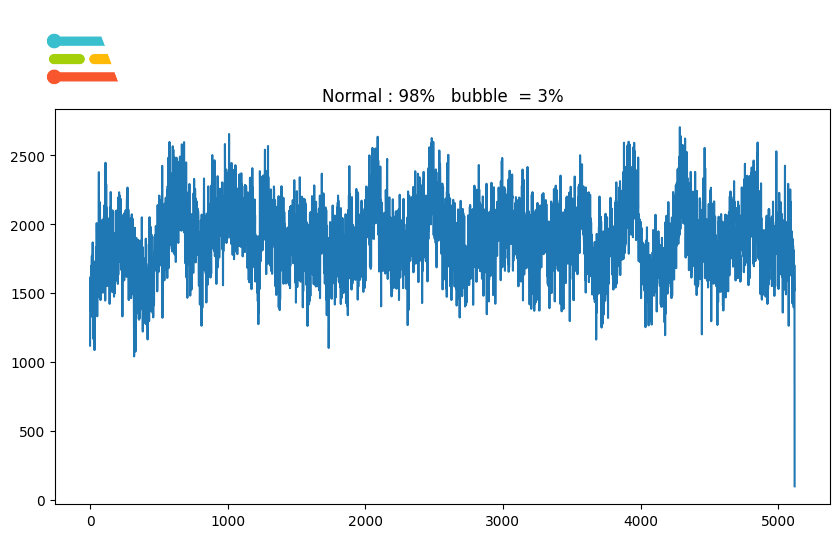
In industrial settings, pumps provide air to power tools, transfer steam for aluminum, paint sprayers, abrasive blast equipment, phase shift refrigerants for air conditioning and refrigeration, and propel gas through pipelines. For some applications like steam making, the industrial pump must provide an optimal laminar liquid flow through the pipelines. Despite their harmless appearance, the bubbles in pumping systems are fundamentally distinct from those children typically blow with a wand. When pressure fluctuations inside the pumps give rise to minuscule bubbles, the ensuing collapse of these bubbles generates shock waves that are both powerful and constant. Over time, these recurring shocks wear down the components of the system through erosion or may lead to ruining the production output. Regarding processing systems, bubbling or bubble cavitation should be avoided at all costs.Our Solution
To address this, we will develop a predictive maintenance solution that gathers vibration data from a motor pump and uses machine learning algorithms to detect any bubble cavitation being formed in the pumping systems, which is considered abnormal behavior. The whole principle of operation of a motor pump is based on moving parts. The process of formation and collapse in cavitation is characterized by its rapid and violent nature, which results in a different vibration signal than a normally operating pump. When such machinery manifests anomalous vibration patterns, a possible malfunction may occur, and critical equipment failure may be coming. Such modifications may occur for hours or days, and human operators seldom pick them up. Such phenomena can be detected by harnessing IoT devices and machine learning algorithms, and maintenance teams may be alerted before machinery failure occurs.Hardware Requirements
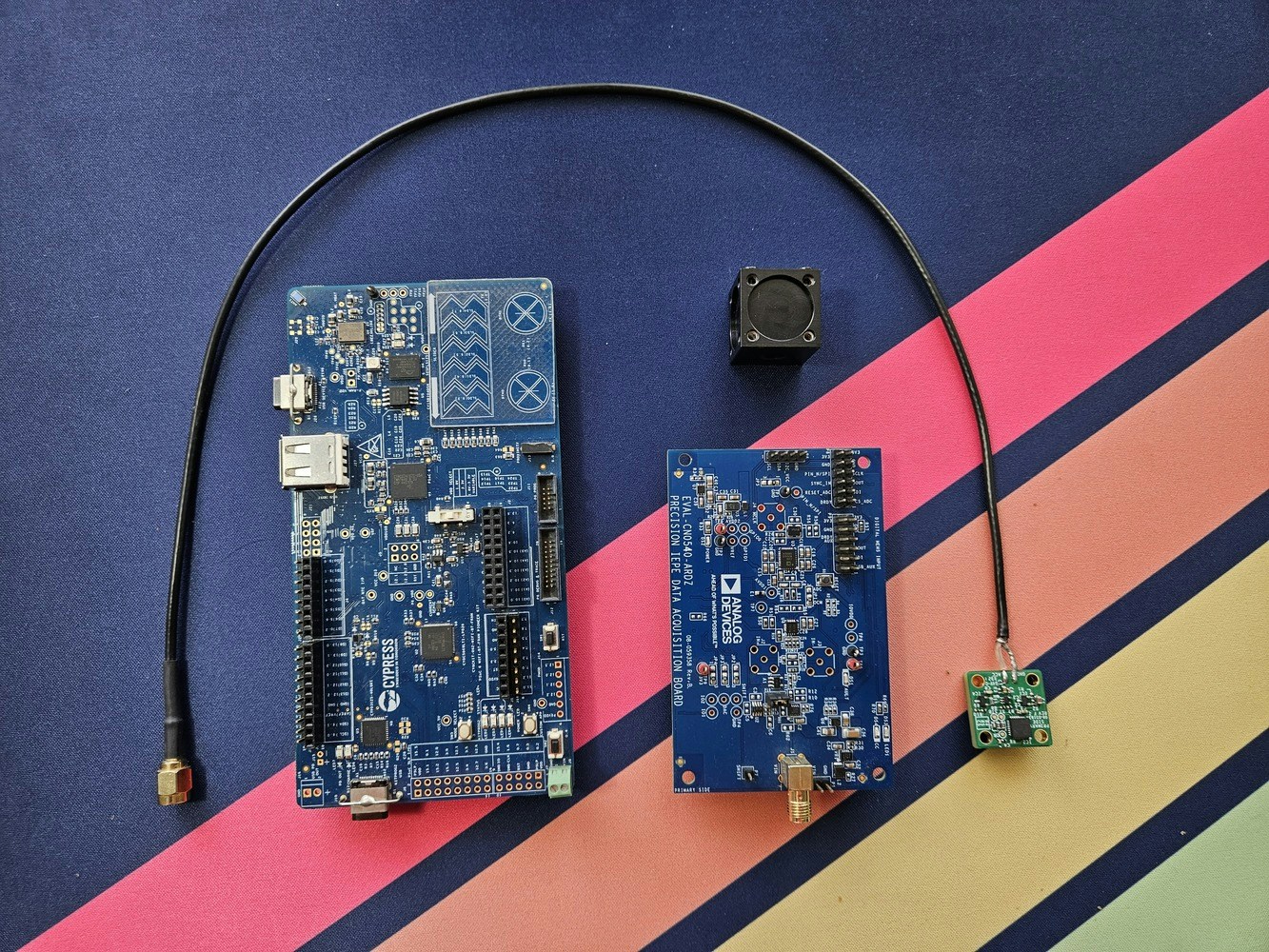
- Infineon PSoC™ 6 WiFi-BT Pioneer Kit
- CN0549 Condition Monitoring Platform
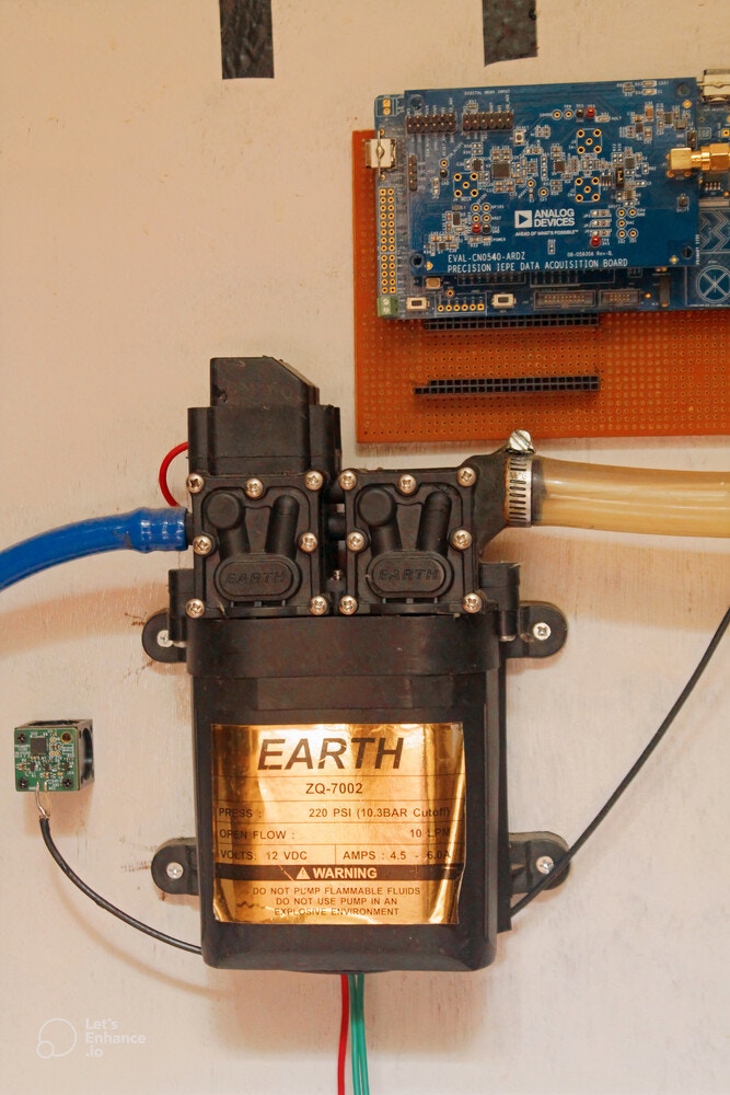
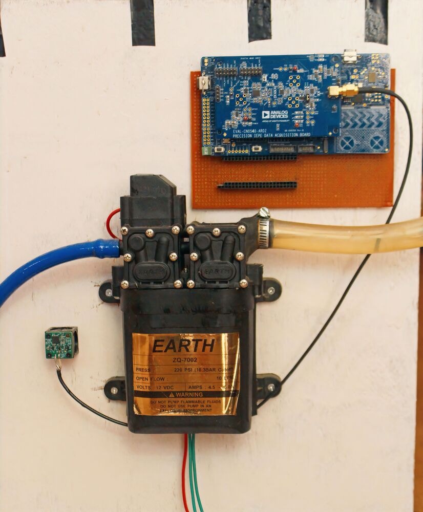
- Industrial Motor Pump
- 2 * USB-C cable
Software requirements
- Edge Impulse account
- Edge Impulse CLI
- Keil Studio Cloud
- Mbed-OS
- Precision Converters Firmware for CN0549
- pyadi-iio 0.14
- libiio 0.24
- Python 3.10
Hardware Setup
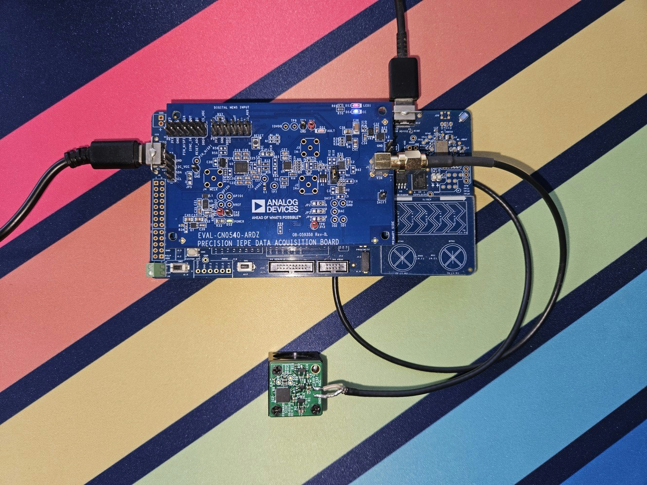
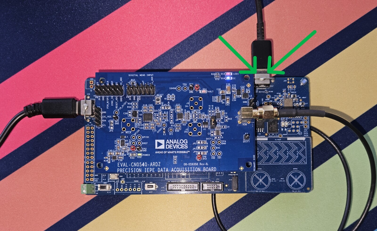
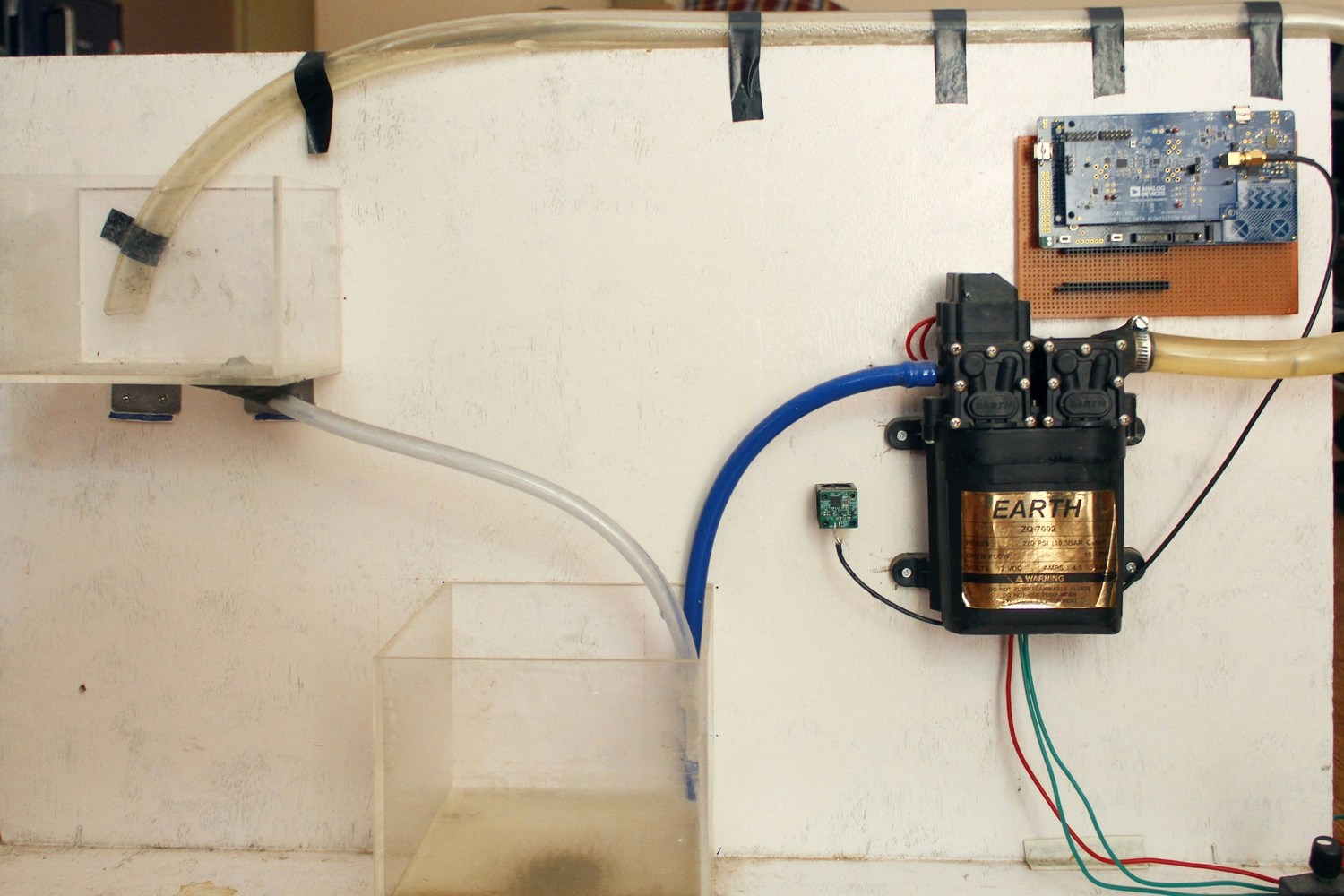
For this application, we will use a condition-based prototyping platform developed by Analog Devices (CN0549) and PSOC 6 Wifi-BT Pioneer Kit by Infineon. The CN0549 is a condition-based monitoring platform based around the integrated electronic piezoelectric (IEPE) standard, a popular signaling interface standard for high-end microelectronic mechanical systems (MEMS) and piezo sensors that are prevalent in industry today. The kit comes with a mechanical mount optimized for vibration fidelity. For setting up the board with the sensor and to learn more about the hardware, please refer to the links below: The anchor of this solution is Infineon’s PSOC 6 Wifi-BT Pioneer Kit. The application processor is performance-optimized and runs at 150 MHz, and the co-processor is an Arm M0 core, which can run at 100 MHz. Both cores are power-efficient. It has a floating-point unit (FPU), an 8 KB 2-way associative cache, 1 MB Flash, and 288 KB RAM. The board also has a capacitive sensing block and the capability of programmable digital and analog blocks known as PSOC. It is an excellent pick for developing edge ML applications requiring a direct sensor interface. Moreover, board Wi-Fi support and a USB host device can be helpful for high-speed data logging. Here are some pictures of the hardware before and after the assembly. Refer to the CN0549 reference guide for sensor-specific modifications, such as selecting coaxial wire and jumper settings. Switch theSW7 to position one on the MCU board side, ensuring that the sensor board is powered from kitprog2 stable VDD supply. Also, ensure the board is in daplink mode for easy debugging in the software section.
Software Setup
Creating an Edge Impulse Project
Let’s start by developing an Edge Impulse project. Log into your Edge Impulse account, pick Create new project from the menu, give it a recognizable name, choose Developer as the project type, and then click Create new project.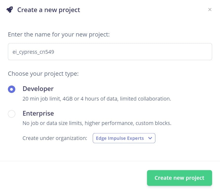
IIO Background
The Industrial I/O subsystem is intended to support a device’s analog to digital or digital to analog converters (ADCs, DACs) or even beyond. It provides a standard interface to talk to converters across different hardware and software platforms. Usinglibiio and other application-specific wrapper libraries, the hardware can talk to any client-side number-crunching applications such as Python or Matlab. Since the firmware for CN0549 is based on the iio stack, we will use the pyadi-iio package to collect data in Python from the firmware.
Before starting to build the dataset, you should install these first, or else the Python code might fail to run:
- pyadi-iio 0.14
- libiio 0.24
- python 3.10
Building the Firmware
The default firmware available for CN0549 is based on mbed-OS and the iiod stack. Since our CY8CKIT-062-WIFI-BT is also mbed-enabled, we can port the existing code to our board with little modifications. I have already done that for you; you can directly import the firmware into the Keil studio cloud from the link below, which lets you build and debug the firmware inside the browser. Some of the modifications done so far to make this compatible are listed below:- Changed the SPI mode in the
user_config.cand pin mappings inapp_config_mbeb.c/.hfiles. If you want to use different pins or configurations; you can change them in these files. - Disabled some of the wireless stacks in the mbed-OS to avoid conflicts. These can be found in the
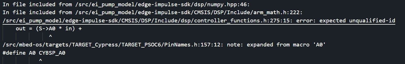
.mbedignorefile in the root of the directory. - Changed pin name in mbed-OS to avoid conflict with the Edge Impulse library. This happens explicitly when using the ARM compiler. With GCC, it builds fine. The modified mbed-OS can be found here. The mbed-OS for our firmware should be cloned from this repository when we import the code into Keil studio.
- We’re using the board as a USB host; you might need to connect another cable to another port.
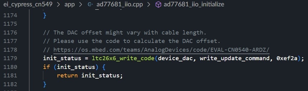
- Change the DAC code in the firmware to remove any DC bias. The IEPE accelerometer has a specific DC bias voltage that must be removed because this voltage does not carry any useful information. This is a crucial step to ensure that you’re receiving reliable data. Even changing the length of the cable connected to the sensor can affect the DC bias. You can use the code and select Option 21 (Compensate Piezo sensor offset), which automatically compensates for voltage offsets in the sensor, giving more accurate data. The user should run this after connecting a new sensor.
- Offset Compensation Code
- Learn more about CN0549 board circuit
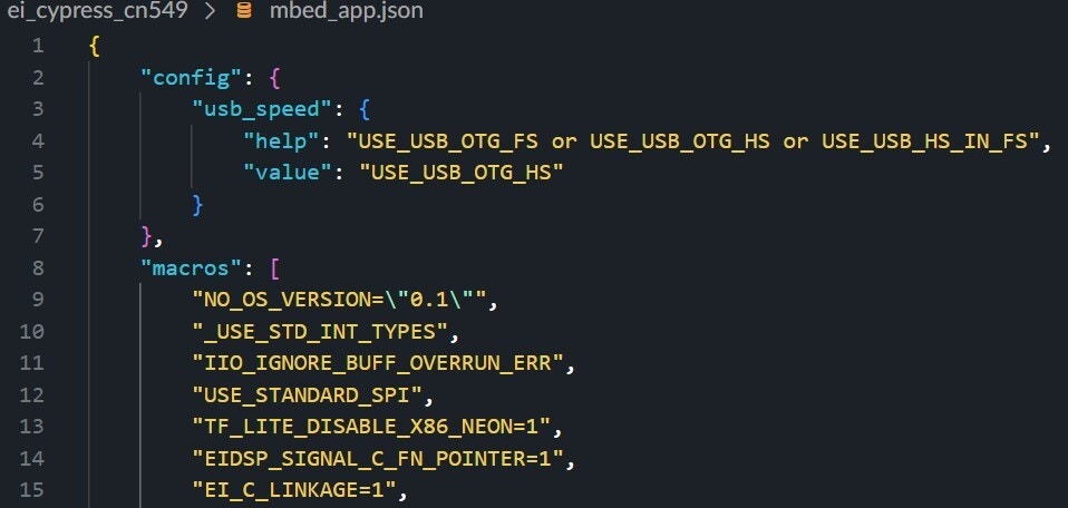
- Since most of the drivers and firmware for the CN0549 are C code and Edge Impulse is C++, we need to use
EI_C_LINKAGE=1flags to build the code properly. Some other flags and configurations can be found in thembed_app.jsonfile.
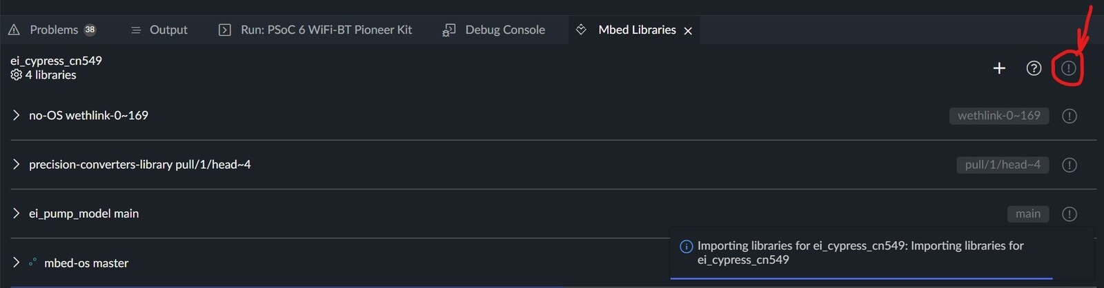
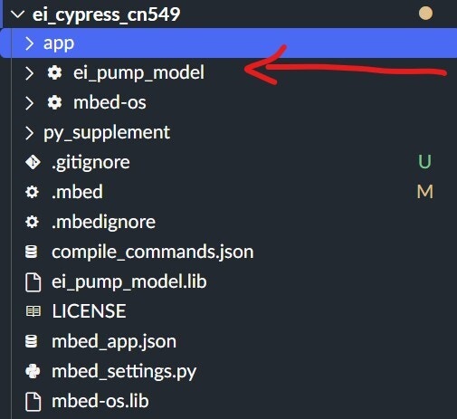
.lib files with specific Commit IDs. Click the “Exclamation mark” shown in the picture below, and that should check out the libraries properly.
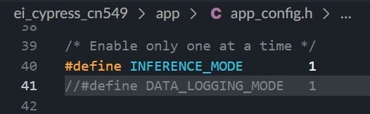
app_config.h file depending upon the intended use. You can either use it for data logging or inferencing. In inference mode, the firmware returns the client two extra bytes of classification results and the accelerometer data.
Building the Dataset
To build the data set, we should collect the data from the device using pyadi-iio drivers in Python and then push it to Edge Impulse using the Ingestion API. You can find the Python drivers in thepy_supplement folder of the firmware repository or visit the following link.
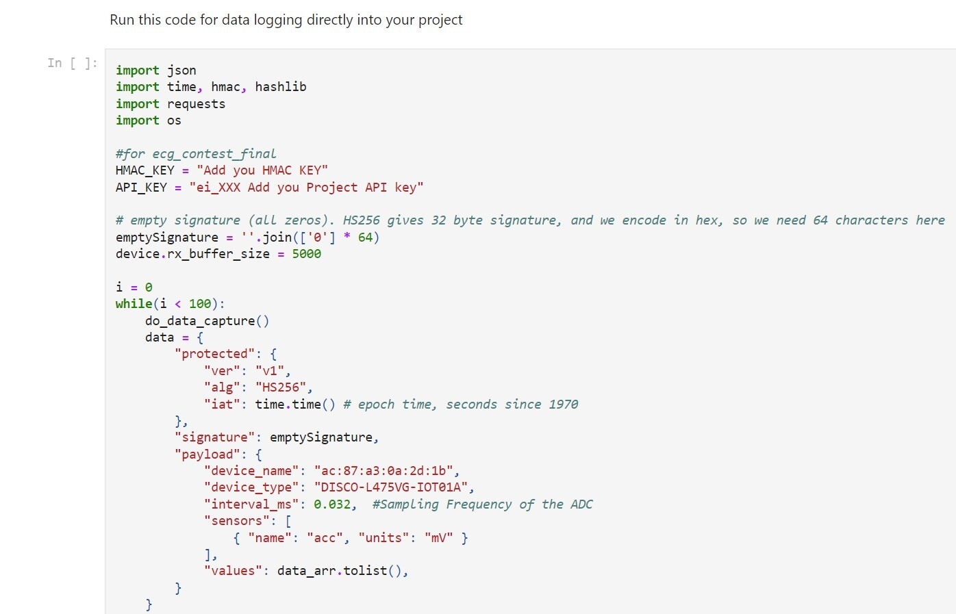
This Jupyter notebook has all the initialization and data logging code. Run all the cells in the notebook one by one, except the last two cells. One is used for inference, and the other is for pushing data into Edge Impulse.
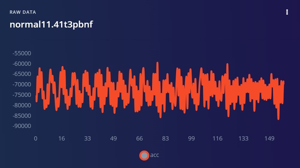
Here is a snapshot of the code. Add your HMAC and API_KEY into the code, and you can also set the sampling frequency (which needs to be in sync with the sampling frequency specified in the firmware) and then run the code.
Changing the block_size will determine the sample length, which also depends on the sampling frequency. Here is a snapshot:
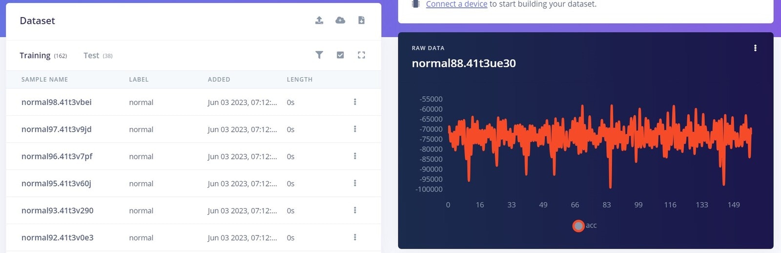
label in the script, and data will be arranged accordingly in the Edge Impulse Studio. You should be able to see your incoming data in the Data acquisition tab.
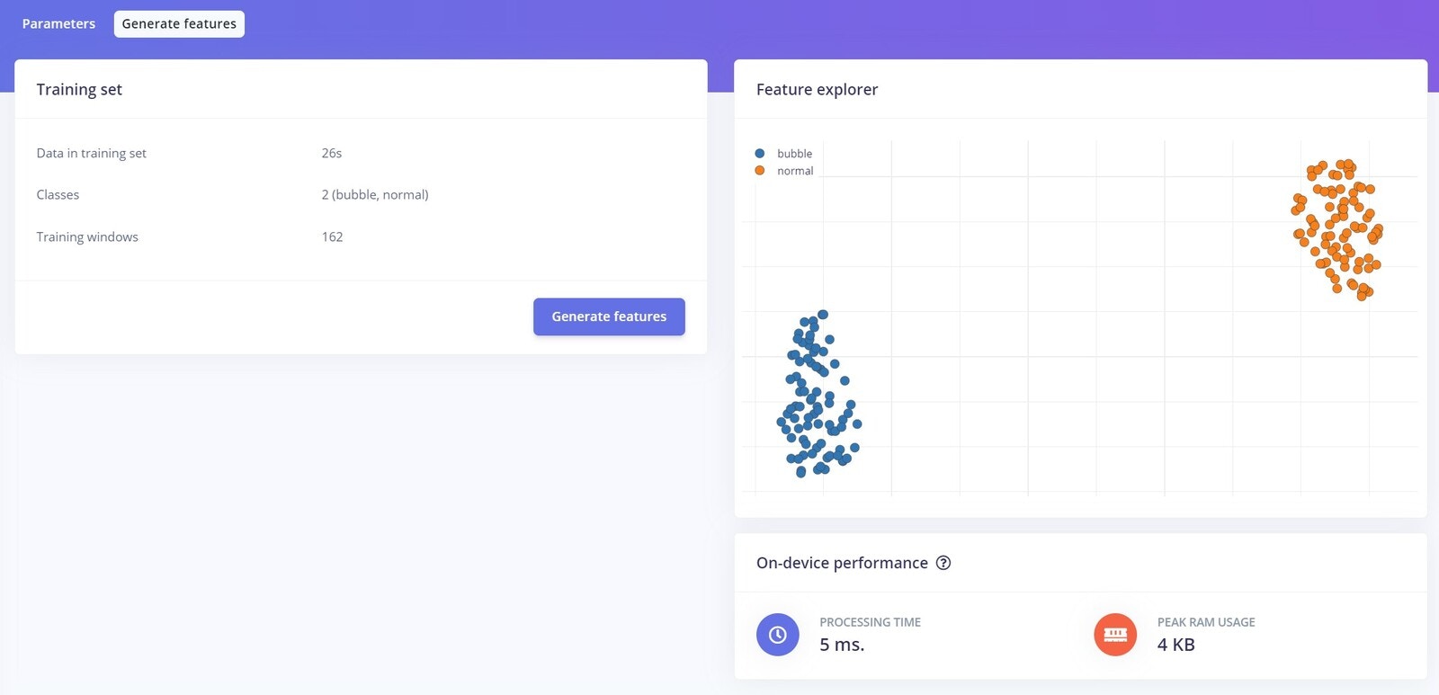
Designing the Impulse
After building the data set, it’s time to create the Impulse. An Impulse is a symbolic pipeline of gathering data, passing it through a preprocessor, feeding it into a neural network, and outputting it, with each step of the process being customizable.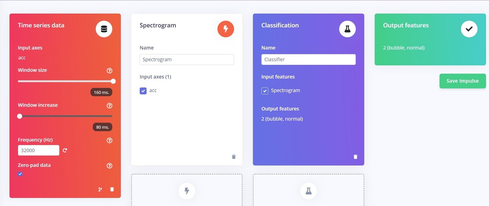
Configure the Spectrogram Block
The Spectrogram processing block extracts time and frequency features from a signal. It performs well on audio data for non-voice recognition use cases or any sensor data with continuous frequencies. Low-pass and high-pass filters can be used in this block to eliminate undesirable frequencies. As with our use case, this block typically performs well when decoding recurrent patterns in a signal, such as those caused by the vibrations or motions picked up by an accelerometer unit. Under the Parameters tab, you can configure your spectrogram features or let the Studio do it by clicking on the “Autotune Parameters” button.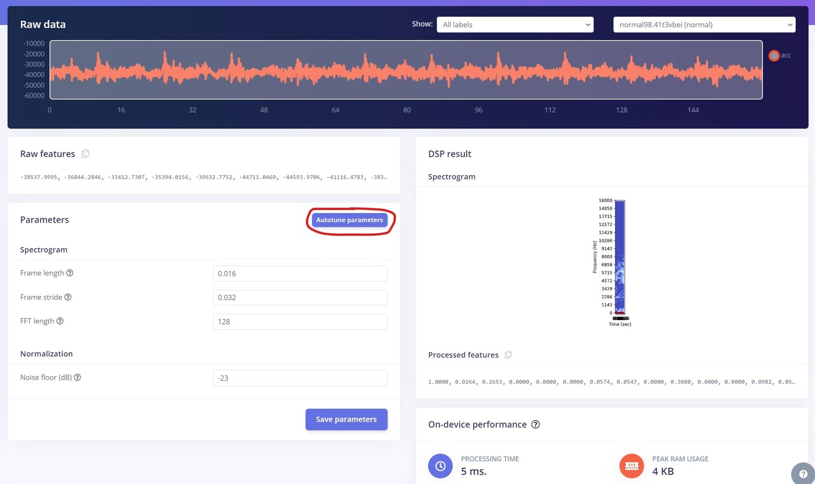
Configure the NN Classifier
The NN Classifier block’s configuration is the next phase in developing the machine learning algorithm. The number of training cycles, learning rate, size of the validation set, and whether or not the Auto-balance dataset function is enabled are just a few of the factors that can be modified. They provide users control over the number of epochs the neural network is trained on, how quickly the weight of the links between neurons is modified each epoch, and the proportion of samples from the training dataset that are used for validation. The architecture of the neural network is detailed, and can be changed as well. Edge Impulse also provides options to augment the preprocessed data, which can help avoid overfitting the model, making it robust against a wide range of input data. Leave everything on default settings for the time being, and click Start training.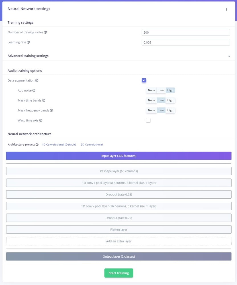
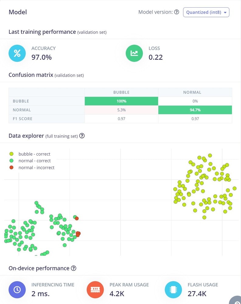
Model Testing
The Model Testing tab allows users to quickly evaluate how the machine learning model fares when presented with new data. The platform uses the data available in the Test data pool, defined during the Data acquisition phase, and evaluates the performance of the model. Since we’re using our custom firmware, live testing is not supported directly. However, if you want to use the live testing option in the Edge Impulse Studio, you can go through the steps in the following link.Deploying the Model on the Edge
Edge Impulse allows users to export the machine learning model they have just created as a pre-compiled binary for the supported platforms without going through the effort of building custom firmware. However, since our platform uses different sensors supported by the original board, we must download the model as a C++ library and then integrate the SDK into our firmware.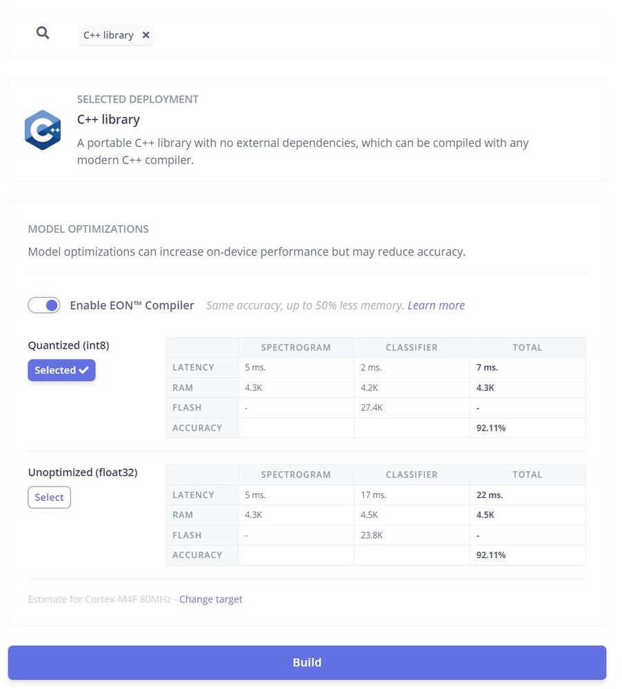
app_config.h file. This will build the code to transport inference results as part of the data stream on the host; on the client side, it should be able to separate it.
Conclusion