

Introduction
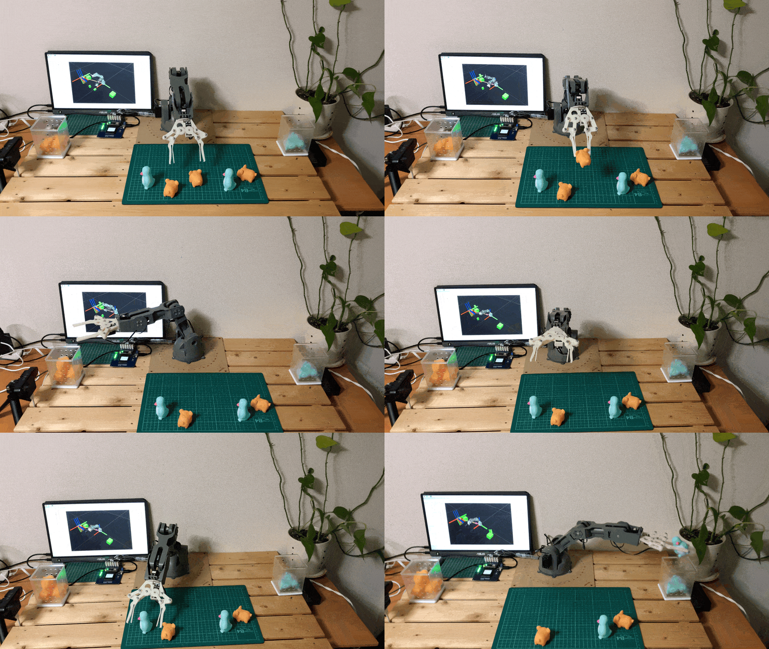
In this project, we will design and implement a system capable of performing pick-and-place tasks using a robot arm and a 3D depth camera. The system can recognize and locate objects in a cluttered and dynamic environment, and plan and execute grasping and placing actions. The system consists of the following components:- A 3D camera that can capture images of the scene and provide 3D information about the objects and their poses.
- A robot arm that can move and orient its end-effector according to the desired position and orientation.
- A gripper that can attach and detach objects of various shapes and sizes.
- A control system that can process the 3D images, perform object recognition and localization, plan the grasping and placing strategies, and control the robot arm and the gripper.
Hardware Selection
We are using Arduino Braccio ++ for the robotic manipulation.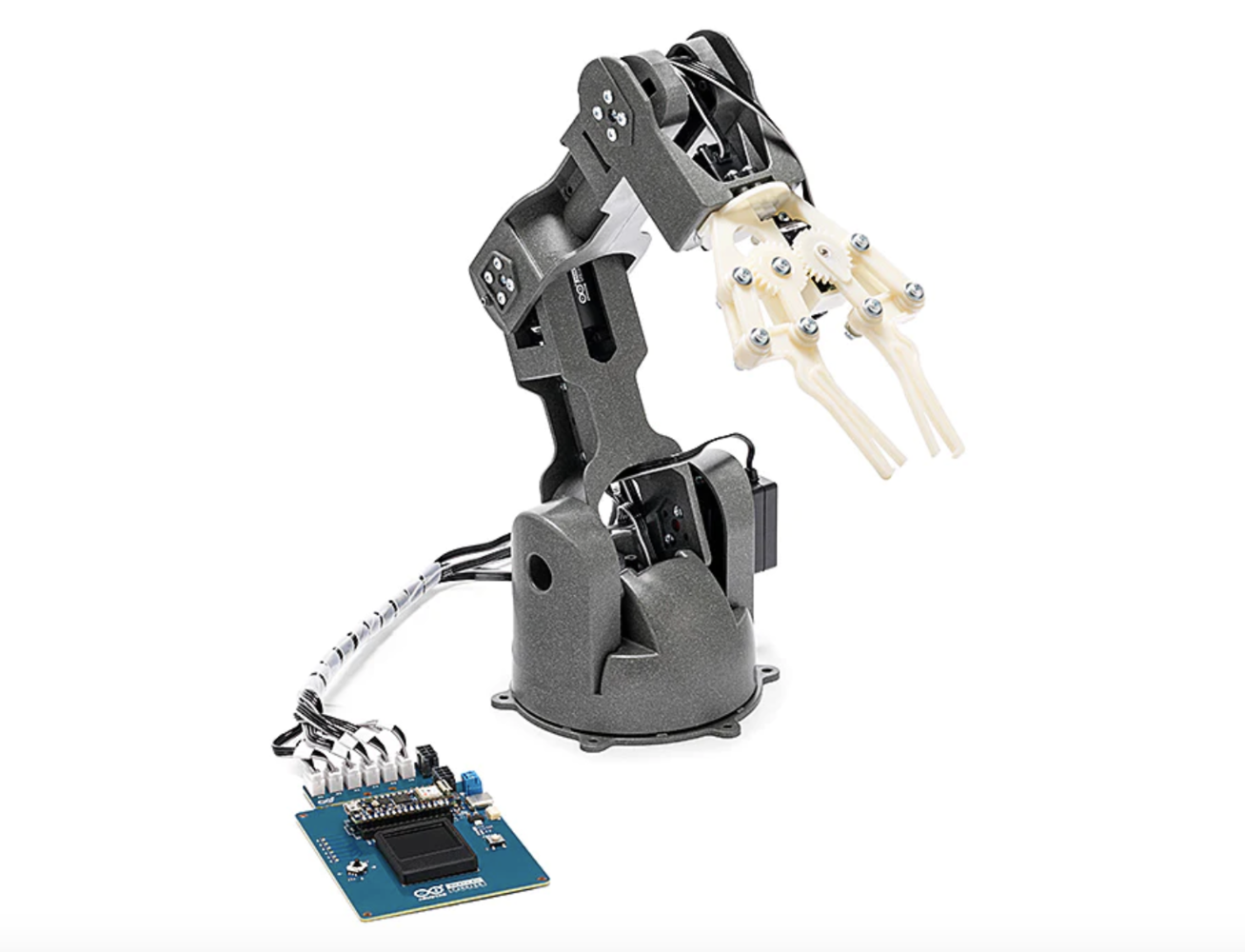
braccio_plus
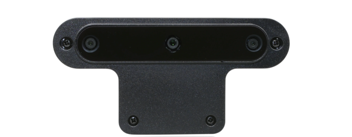
oakd
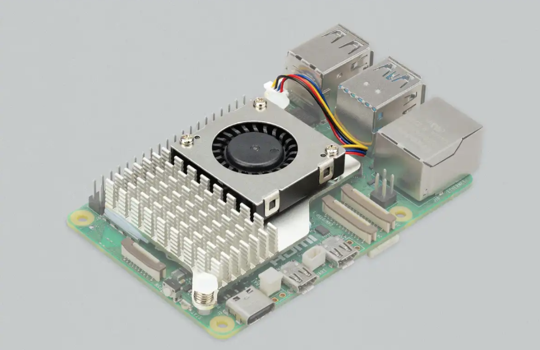
rpi5
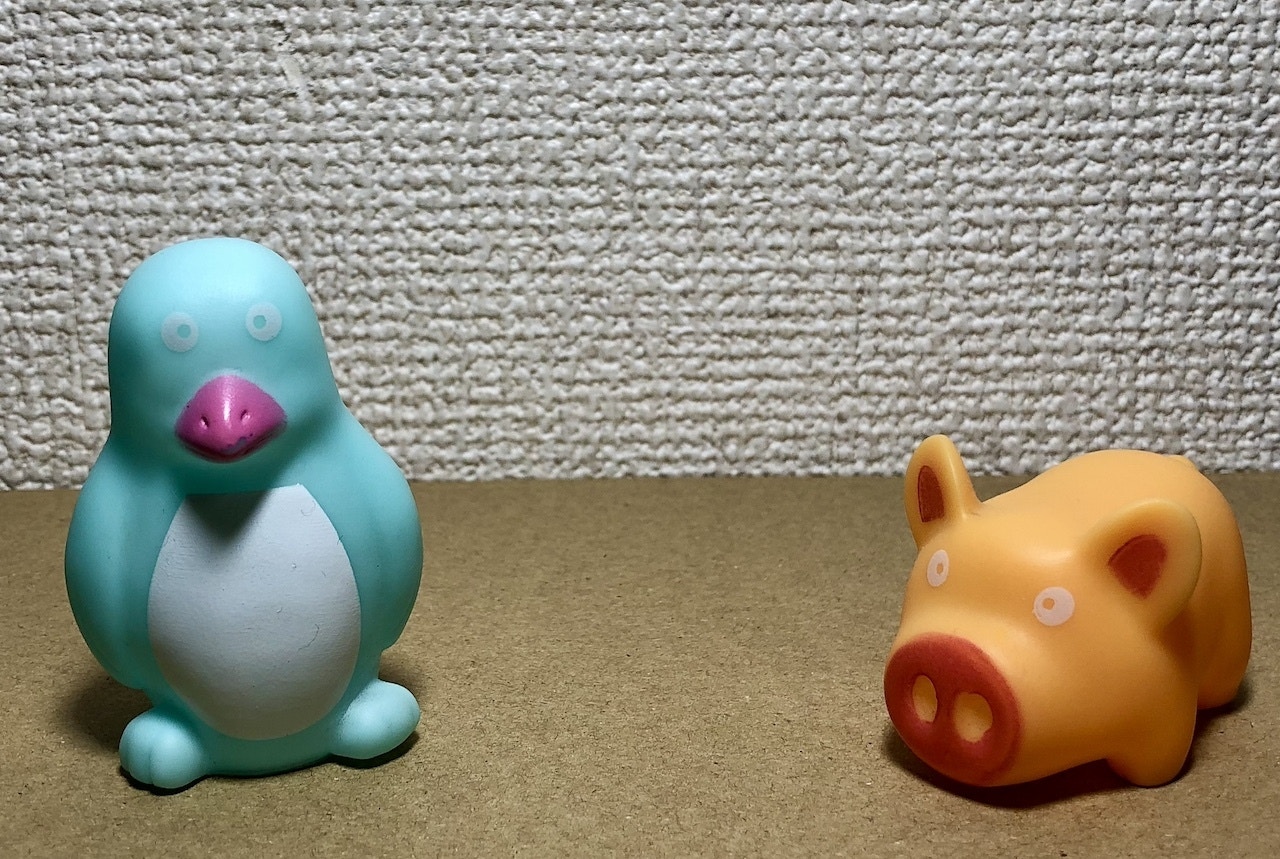
Toys
Setting up the Development Environment
We can use the Raspberry Pi Imager to install the Raspberry Pi OS (64-bit, Bookworm) on an SD card. The Raspberry Pi Imager allows for easy setup of user accounts, Wi-Fi credentials, and SSH server.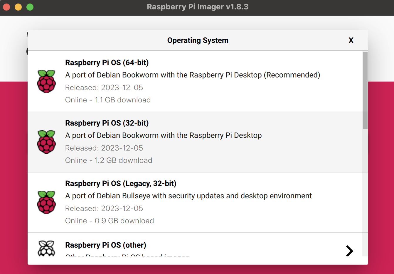
rpi_imager
Installing ROS 2 Humble
The Robot Operating System (ROS) is a set of software libraries and tools for building robot applications. We will use ROS 2 Humble for this project since it is stable on the Raspberry Pi OS. The ROS 2 binary packages are not available for Raspberry Pi OS, so we need to build it from the source. Please follow the steps below to install it.Set locale
Make sure we have a locale that supportsUTF-8.
Localisation Options > Local, choose en_US.UTF-8.
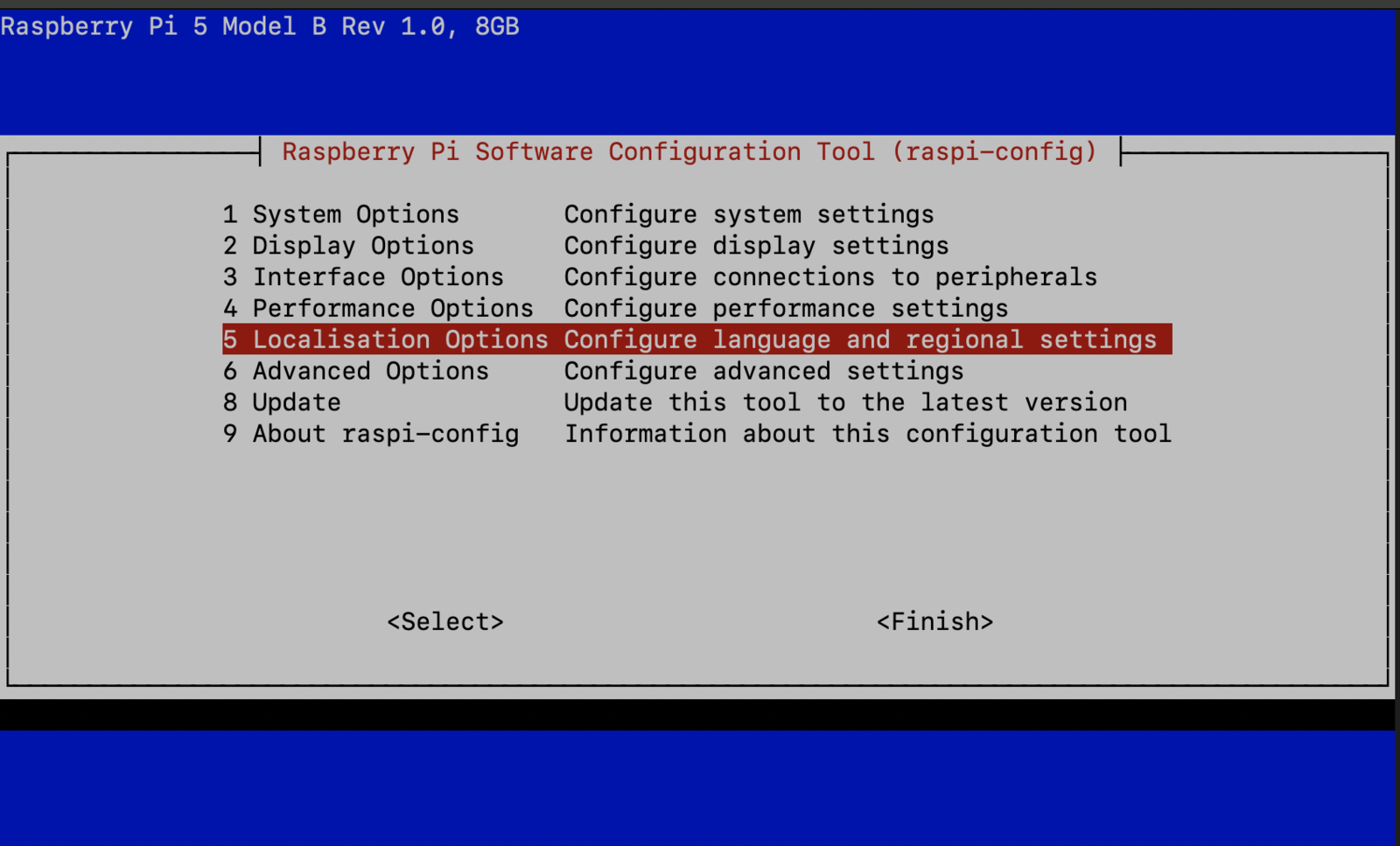
locale_1
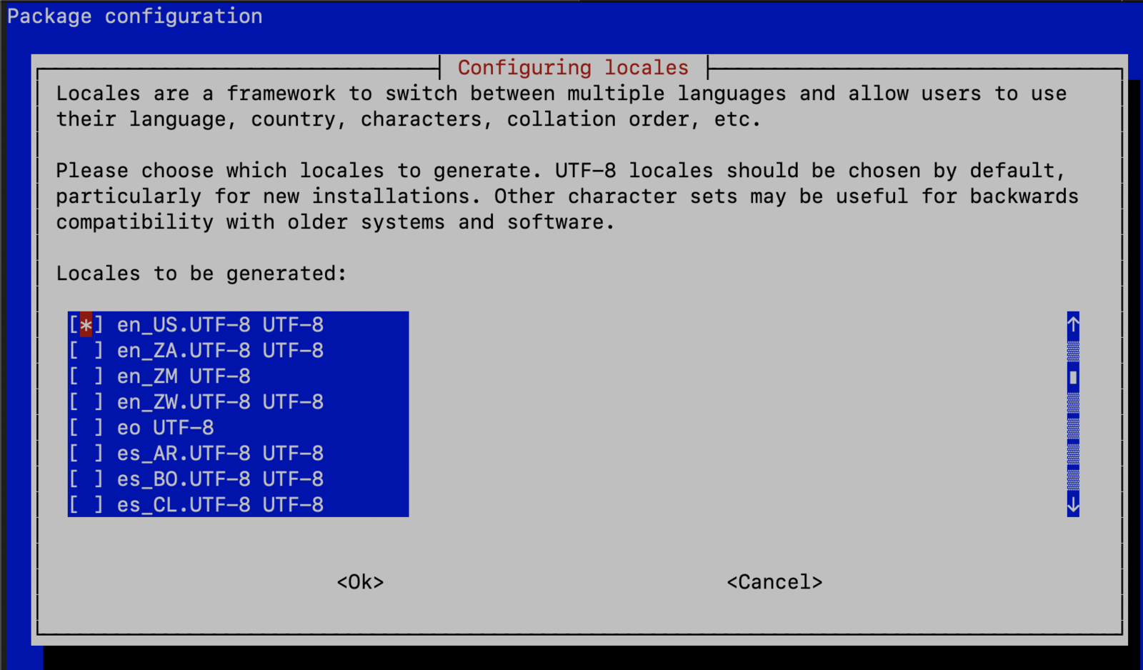
locale_2
Add the ROS 2 apt repository
Install development tools and ROS tools
Build ROS 2 Humble
MoveIt 2 Installation
MoveIt 2 is the robotic manipulation platform for ROS 2 and incorporates the latest advances in motion planning, manipulation, 3D perception, kinematics, control, and navigation. We will be using it to set up the robotic arm and the motion planning.DepthAI ROS Installation
DepthAI ROS is a ROS 2 package that allows us to:- Use the OAK-D camera as an RGBD sensor for the 3D vision needs.
- Load Neural Networks and get the inference results straight from the camera.
micro-ROS
The micro-ROS stack integrates microcontrollers seamlessly with standard ROS 2 and brings all major ROS concepts such as nodes, publishers, subscriptions, parameters, and lifecycle onto embedded systems. We will use micro-ROS on the Arduino Nano RP2040 Connect mounted on the Braccio Carrier board. The Arduino Nano RP2040 will publish the joint states and subscribe to the arm manipulation commands. It will communicate to ROS 2 on the Raspberry Pi 5 over serial port transports.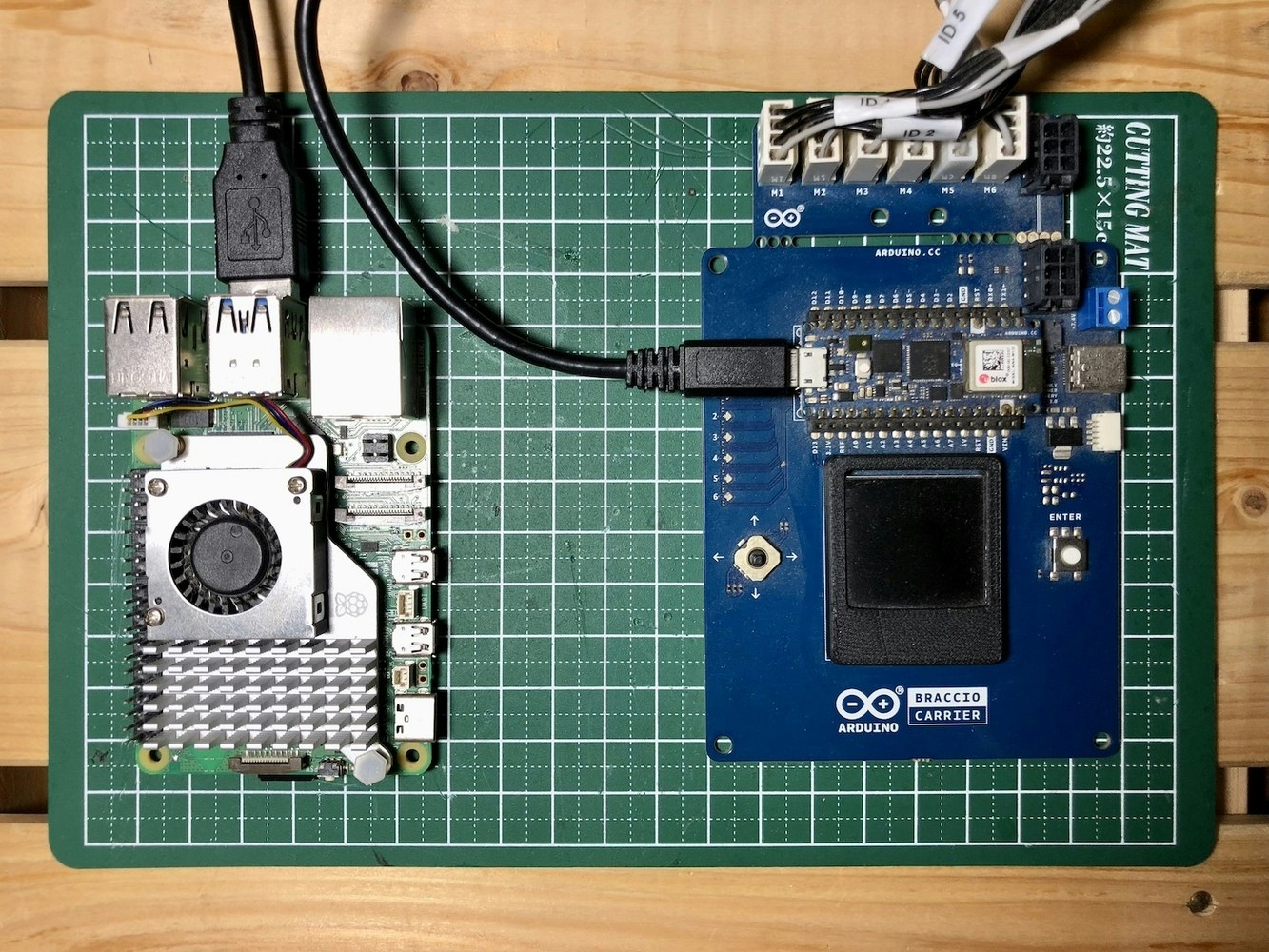
braccio_carrier
micro-ROS Agent Installation
The micro-ROS agent is a ROS 2 node that receives and sends messages from micro-ROS nodes and keeps track of the micro-ROS nodes, exposing them to the ROS 2 network. Execute the following command to install the micro-ROS agent on the Raspberry Pi 5.Data Collection
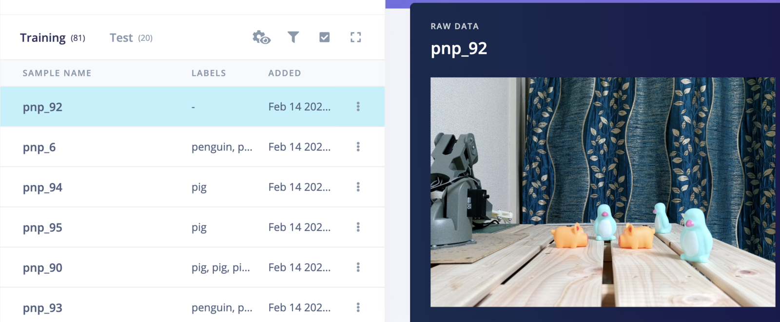
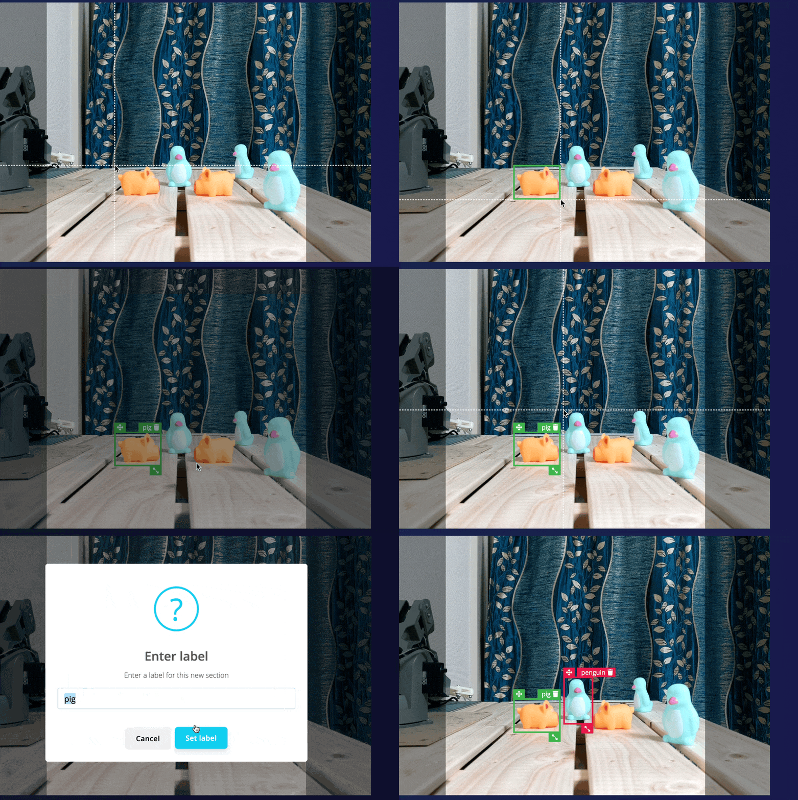
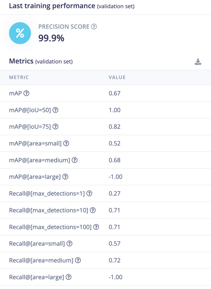
We captured 101 images of the pigs and penguins using the OAK-D camera and uploaded them to Edge Impulse Studio.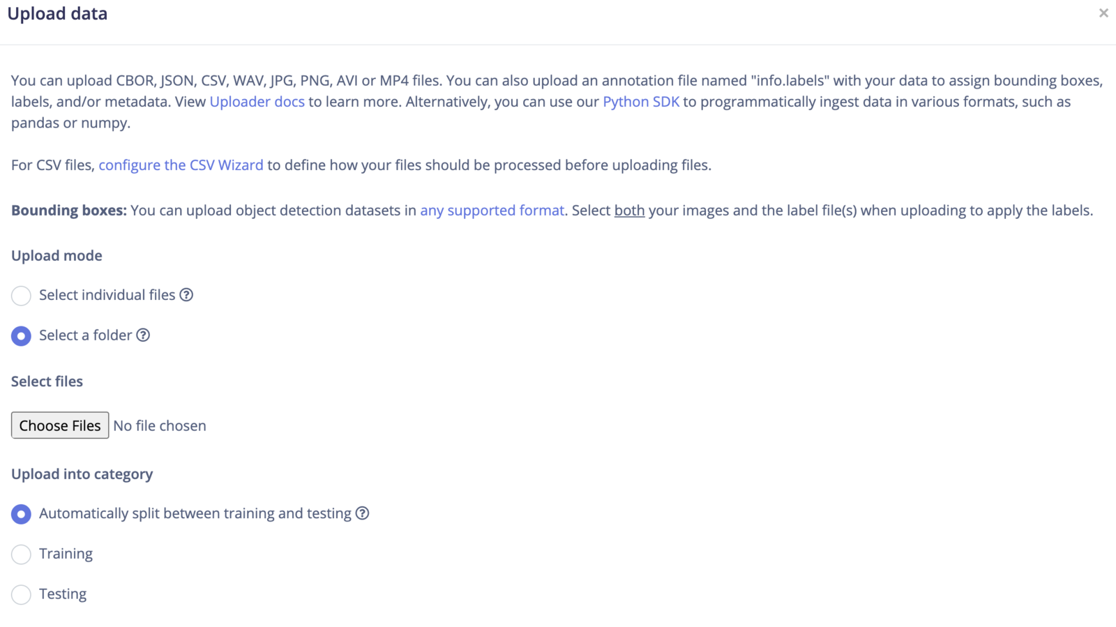
upload_data
datasets
labelling
Model Training
To create an Impulse, follow these steps:- Go to the Impulse Design section, then select the Create Impulse page. We have opted for a 320x320 pixel image size in the “Image Data” form fields to achieve better accuracy.
- Click on “Add a processing block” and choose “Image”. This step will pre-process and normalize the image data while also giving us the option to choose the color depth.
- Click on “Add a learning block” and choose “Object Detection (Images)”.
- Finally, click on the “Save Impulse” button to complete the process.
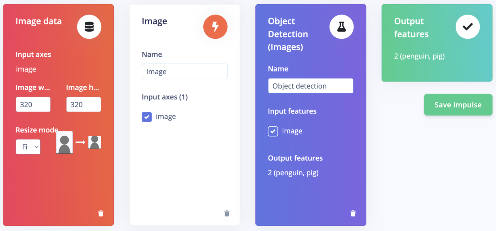
create_impulse
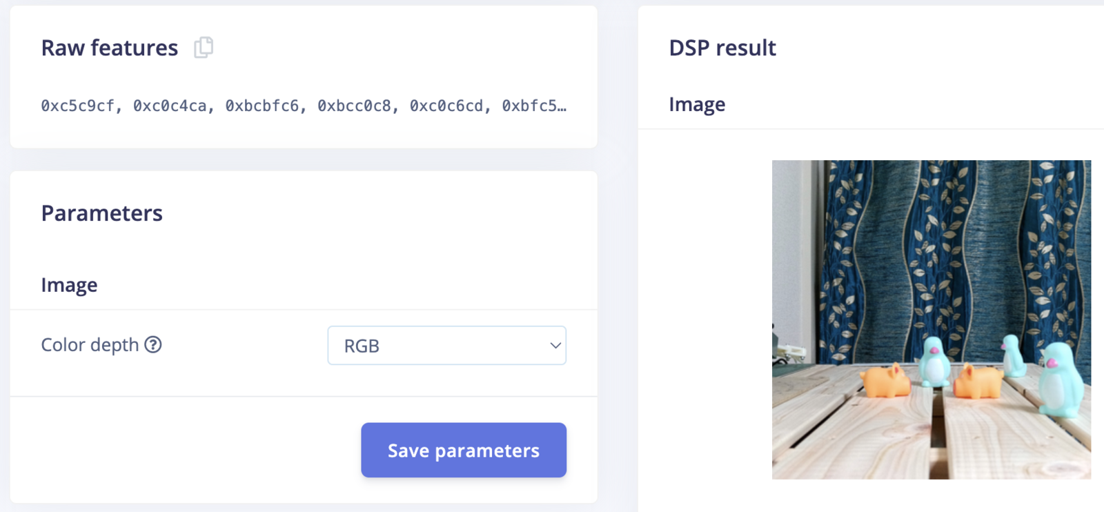
raw_features
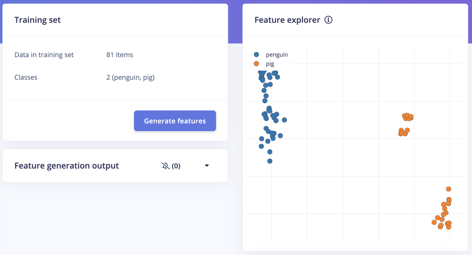
generate_features
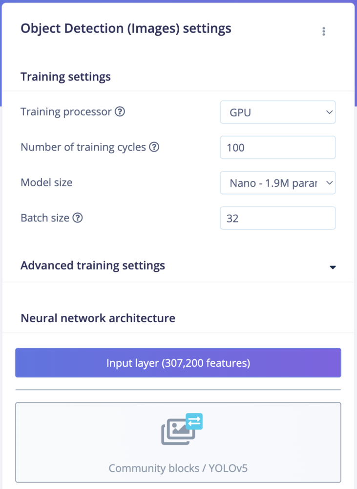
Toys
Toys
Model Testing
On the Model testing page, click on the “Classify All” button which will initiate model testing with the trained float32 model. The testing accuracy is 100%.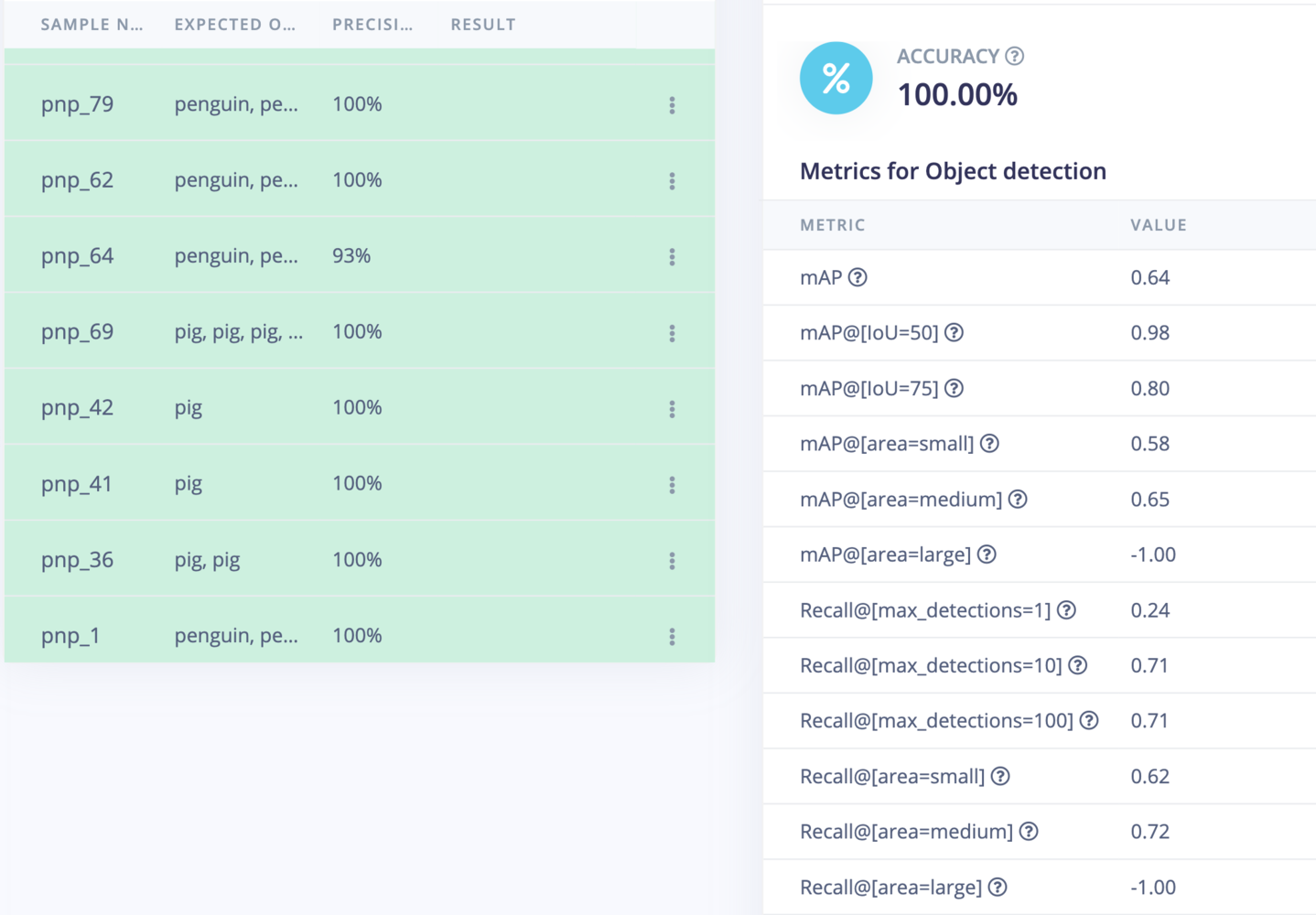
model_testing
Model Deployment
To verify the model, we will run the inferencing on the Raspberry Pi 5 (CPU) before deploying it to the OAK-D device. Execute the following commands to install the Edge Impulse Linux Runner.eim model and start the inferencing, run the following command and follow the instructions.
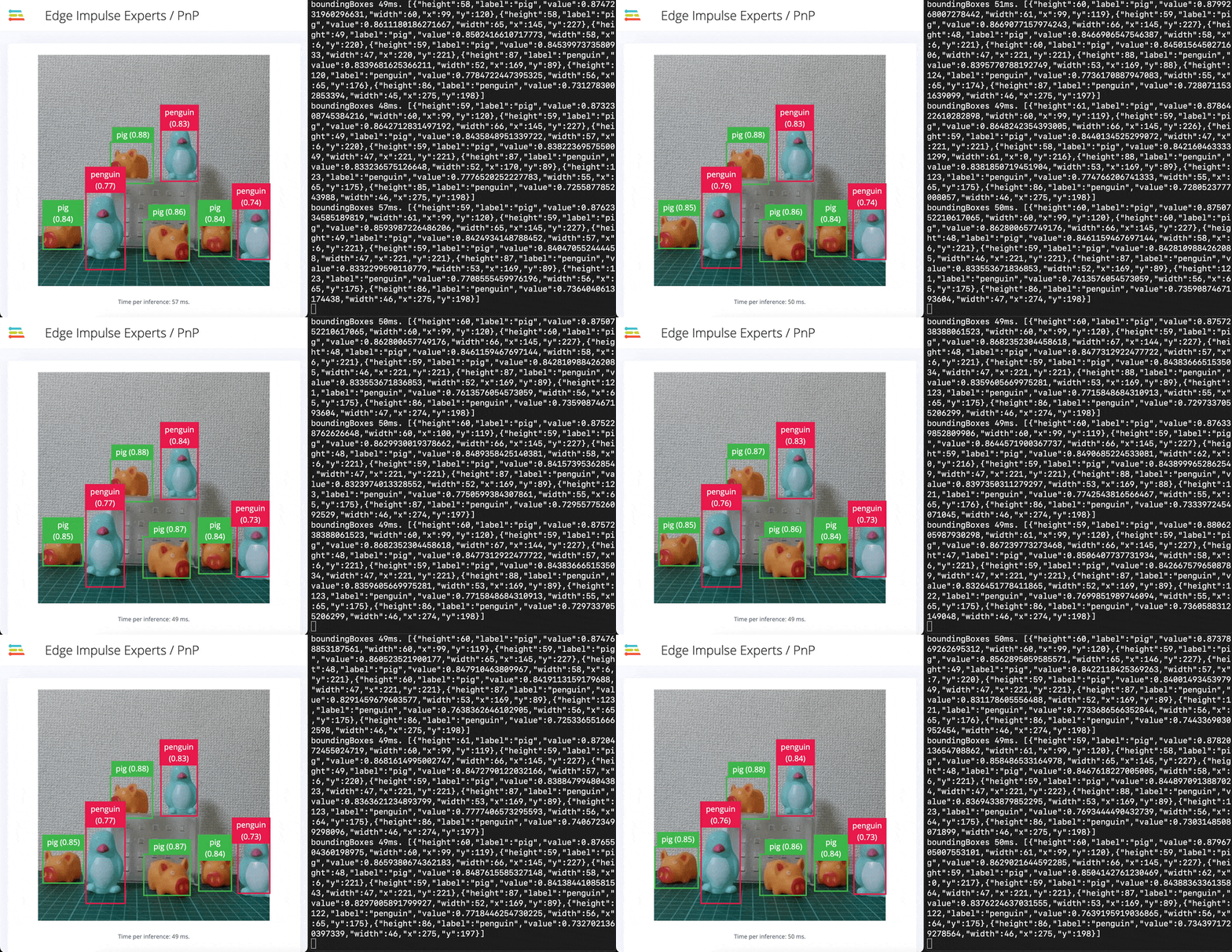
inferencing
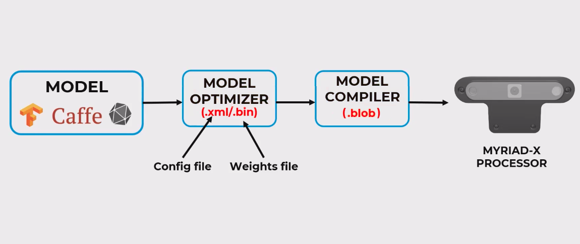
model_compile
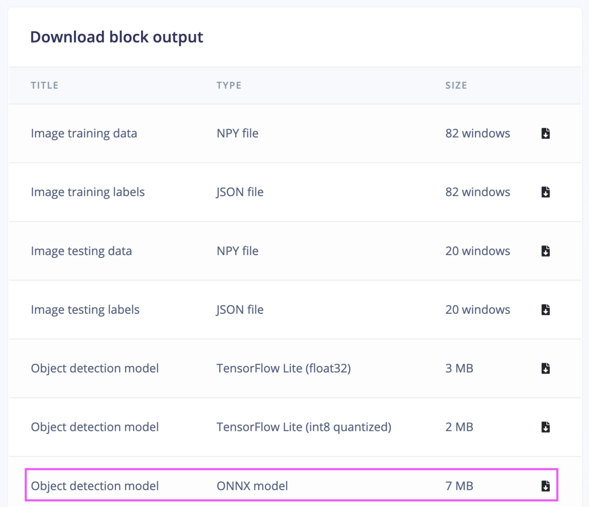
download_block_output
.xml- Describes the model topology..bin- Contains the weights and binary data.
.blob file, which can be deployed to the OAK-D device.
~/EI_Pick_n_Place/pnp_ws/src/ei_yolov5_detections/resources folder on the Raspberry Pi 5. We can test the generated model using the depthai-python library:
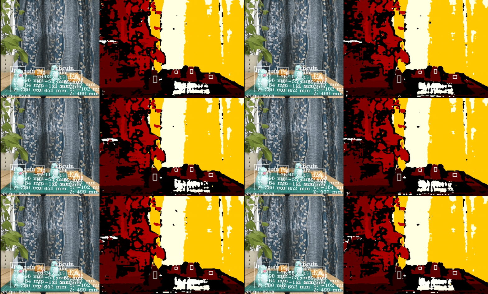
depth_inferencing
Setup the Robotic Arm
Build a visual robot model
First, we need to define a visual model of the Arduino Braccio ++ using the URDF (Unified Robot Description Format) which is a file format for specifying the geometry and organization of robots in ROS 2. We will be using the publicly available STL files for the parts of the robot. We can see one of the STL parts (shoulder) in the following GIF.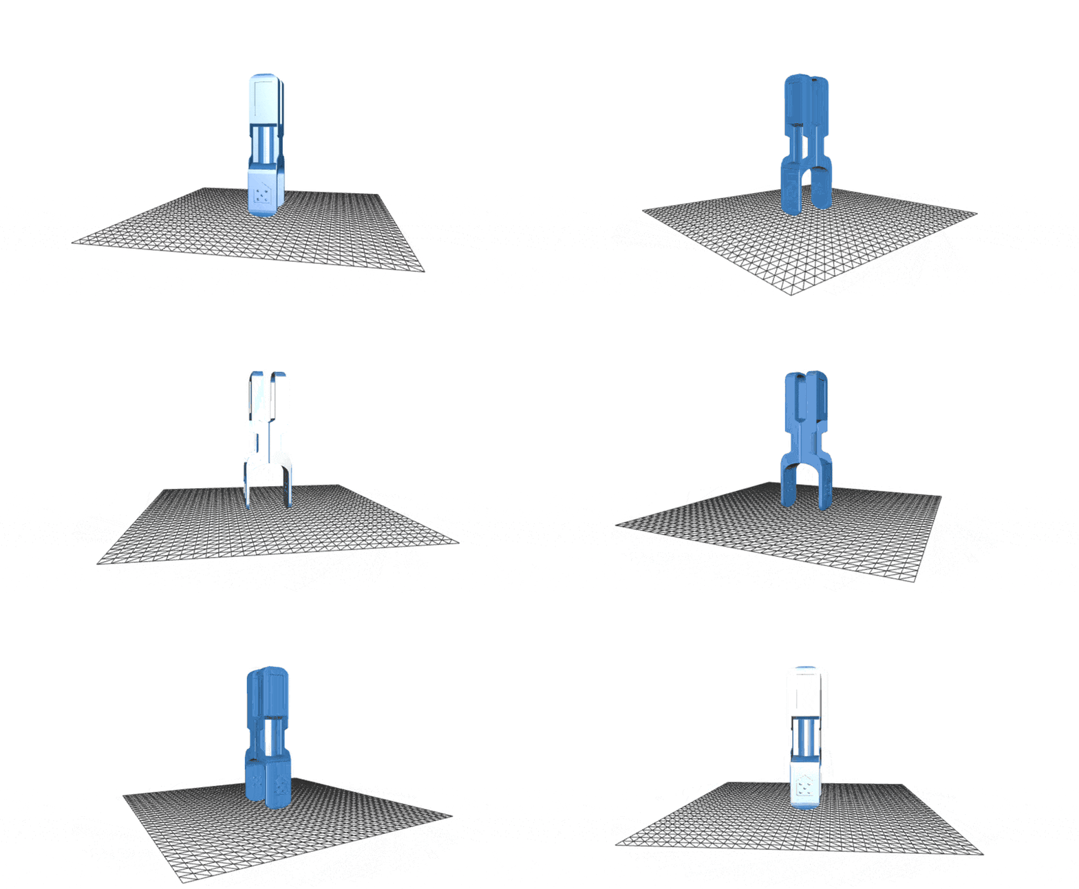
stl
moveit_resources_braccio_description to keep all STL files and URDF for reusability. The robot model URDF can be found in the GitHub repository for this project:
https://github.com/metanav/EI\_Pick\_n\_Place/tree/main/pnp\_ws/src/braccio\_description/urdf
Verify the robot model
We can verify if the URDF is functioning as expected by publishing simulated joint states and observing the changes in the robot model using the RViz 2 graphical interface. Execute the following commands to install theurdf_launch and joint_state_publisher packages and launch the visualization.
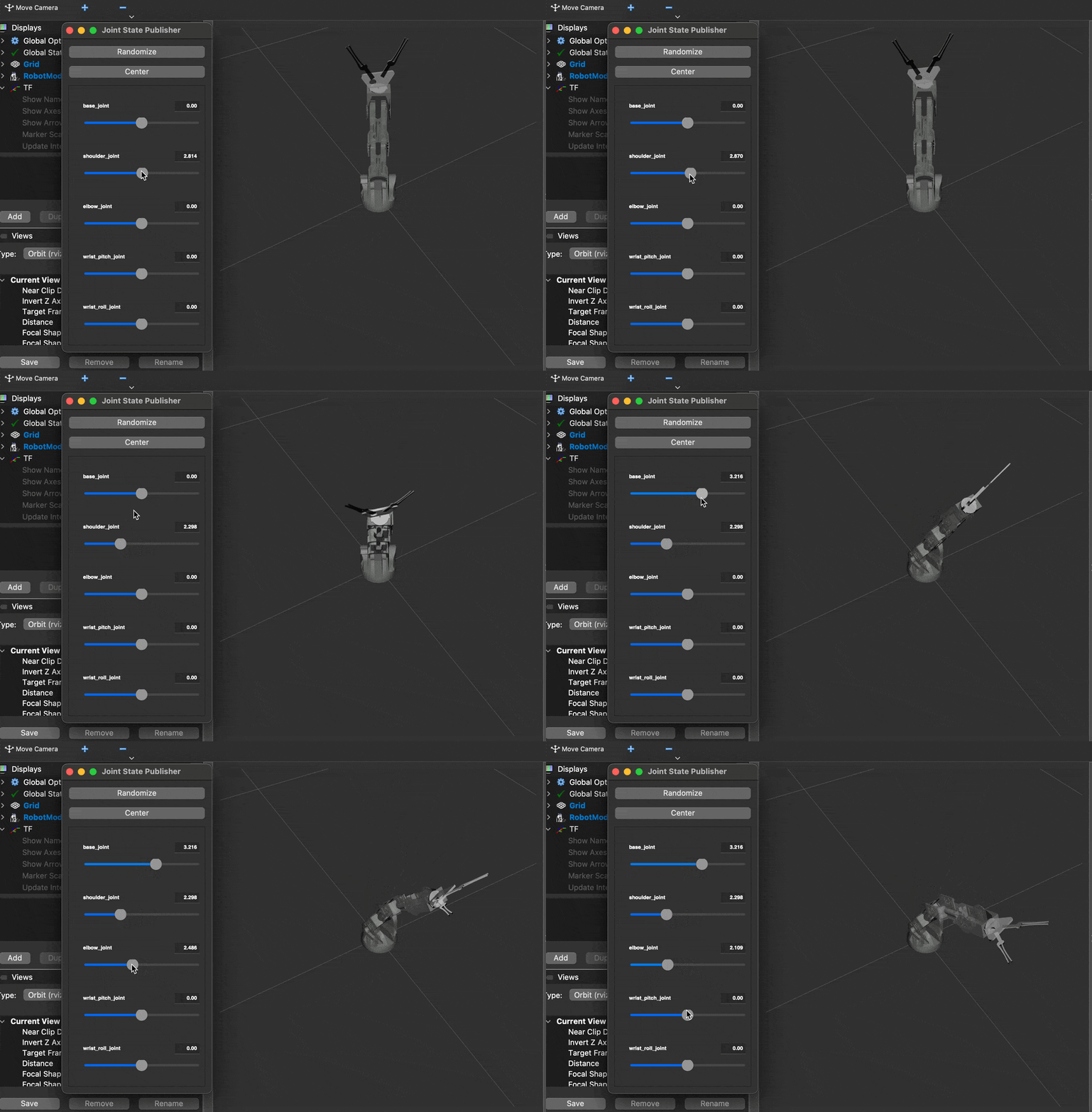
robot_urdf_rviz
Generate configuration using the MoveIt Setup Assistant 2.0
The MoveIt Setup Assistant 2.0 is a GUI for configuring the manipulator for use with MoveIt 2. Its primary function is generating a Semantic Robot Description Format (SRDF) file for the manipulator, which specifies additional information required by MoveIt 2 such as planning groups, end effectors, and various kinematic parameters. Additionally, it generates other necessary configuration files for use with the MoveIt 2 pipeline. To start the MoveIt Setup Assistant 2.0, execute the commands below.braccio.urdf file from the moveit_resources_braccio_description package.
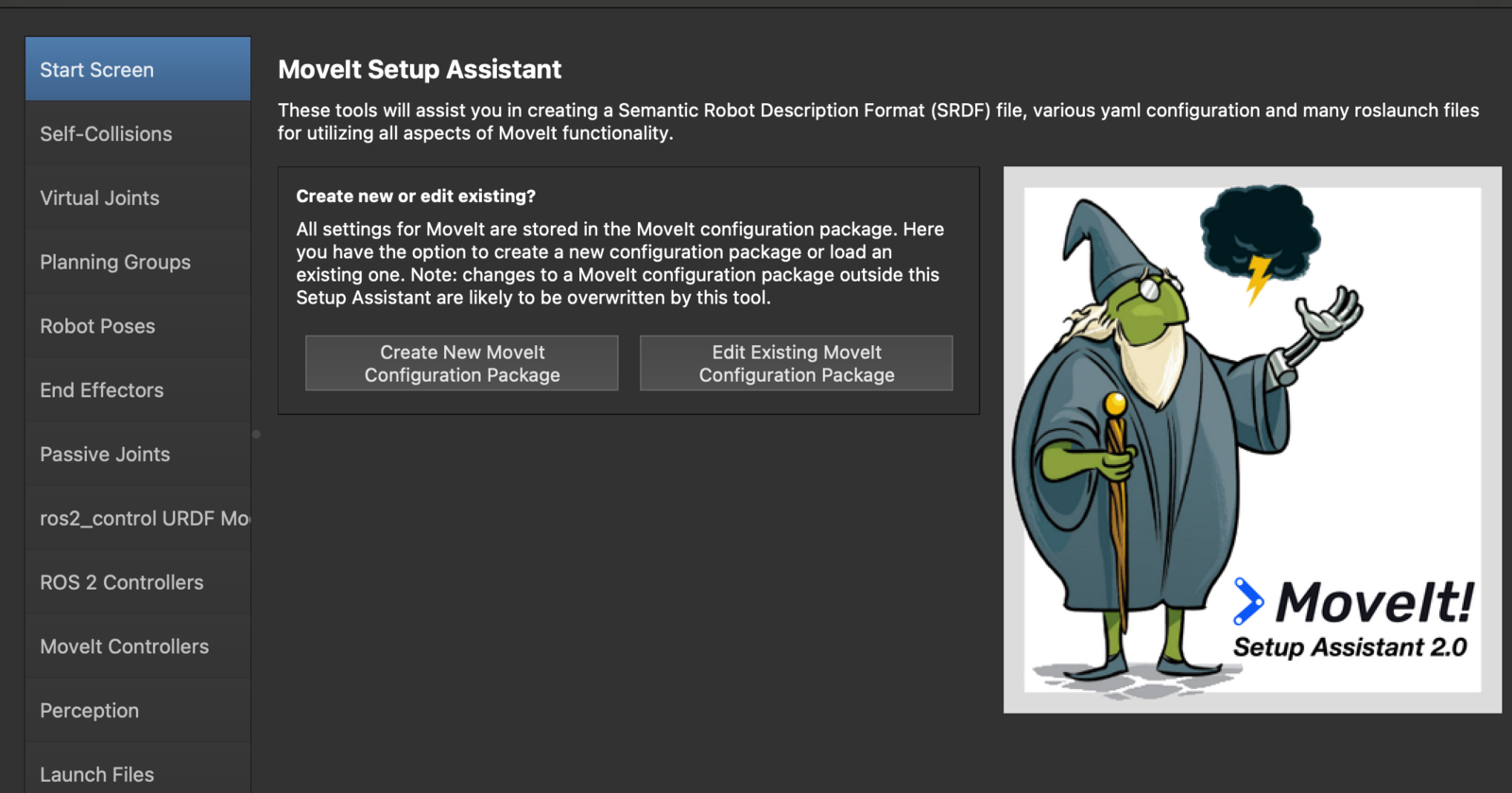
moveit2_assistant_1
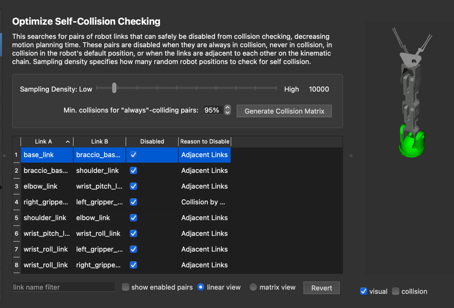
moveit2_assistant_2
fixed virtual joint that attaches the base_link of the arm to the world frame. This virtual joint signifies that the base of the arm remains stationary in the world frame.
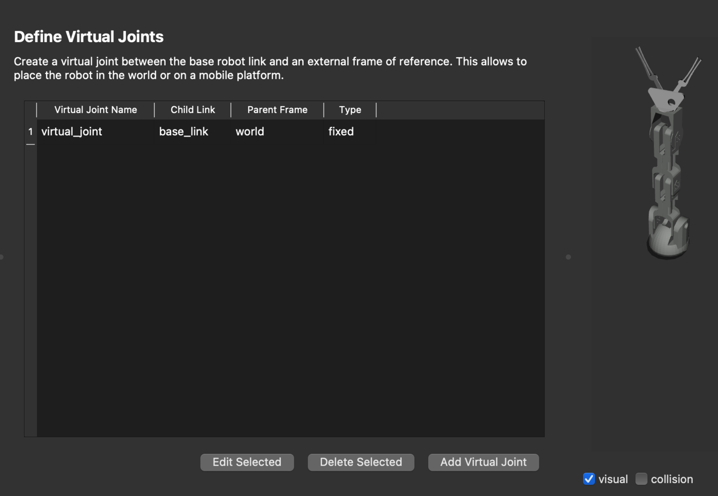
moveit2_assistant_3
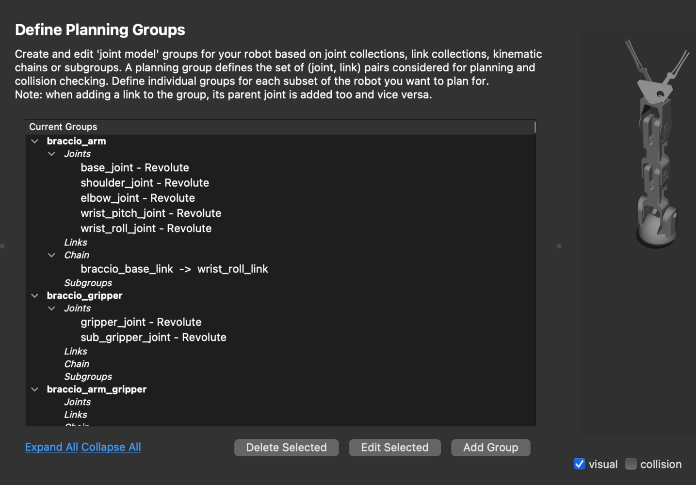
moveit2_assistant_4
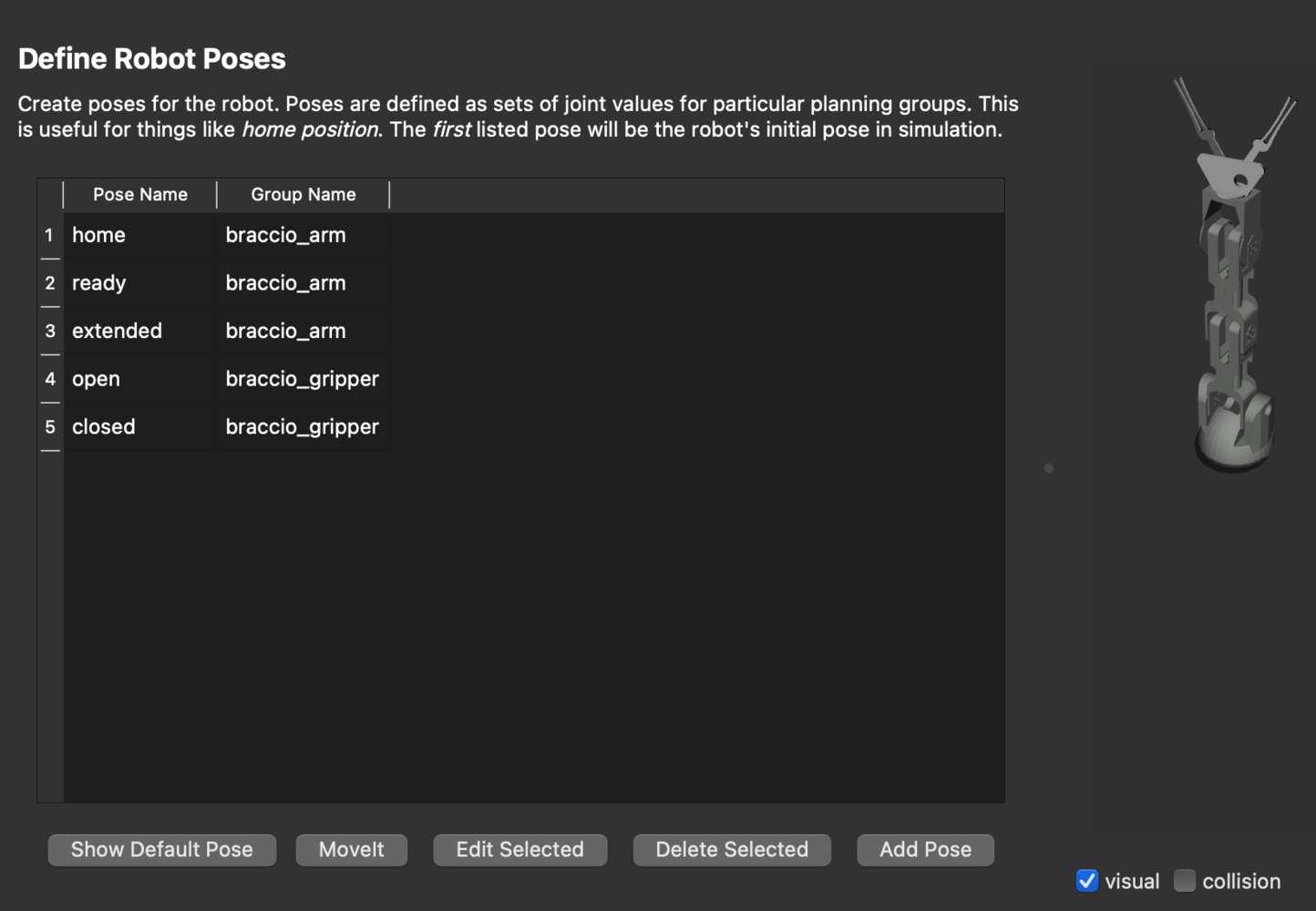
moveit2_assistant_5
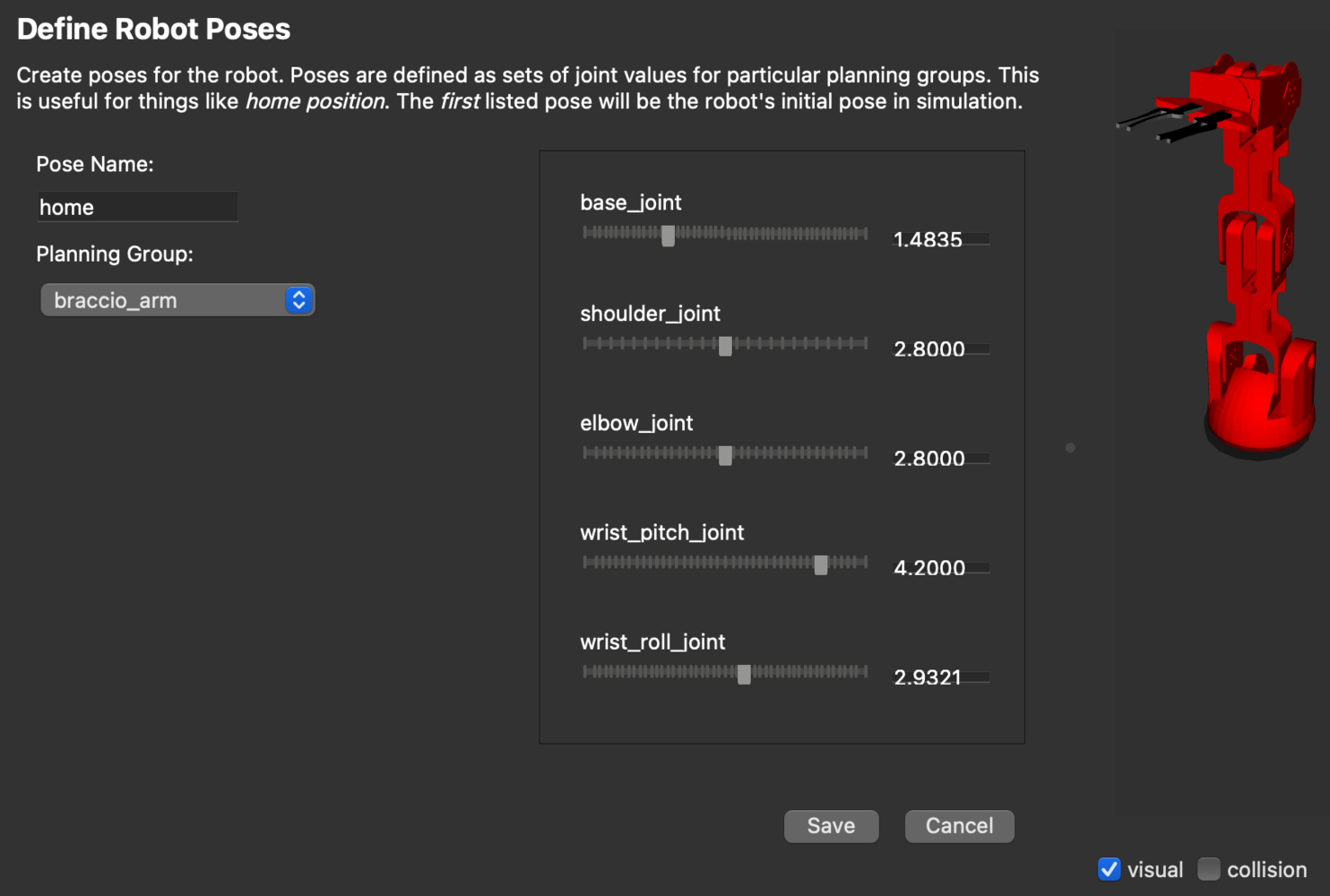
moveit2_assistant_7
braccio_gripper group as an end effector. The end effectors can be used for attaching objects to the arm while carrying out pick-and-place tasks.
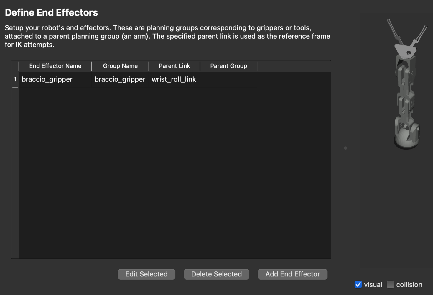
moveit2_assistant_6
Arduino Braccio++ Controller Firmware
Please follow the instructions here to download and install the Arduino IDE. After installation, open the Arduino IDE and install the board package for the Arduino Mbed OS Nano Boards by going to Tools > Board > Boards Manager. Search the board package as shown below and install it.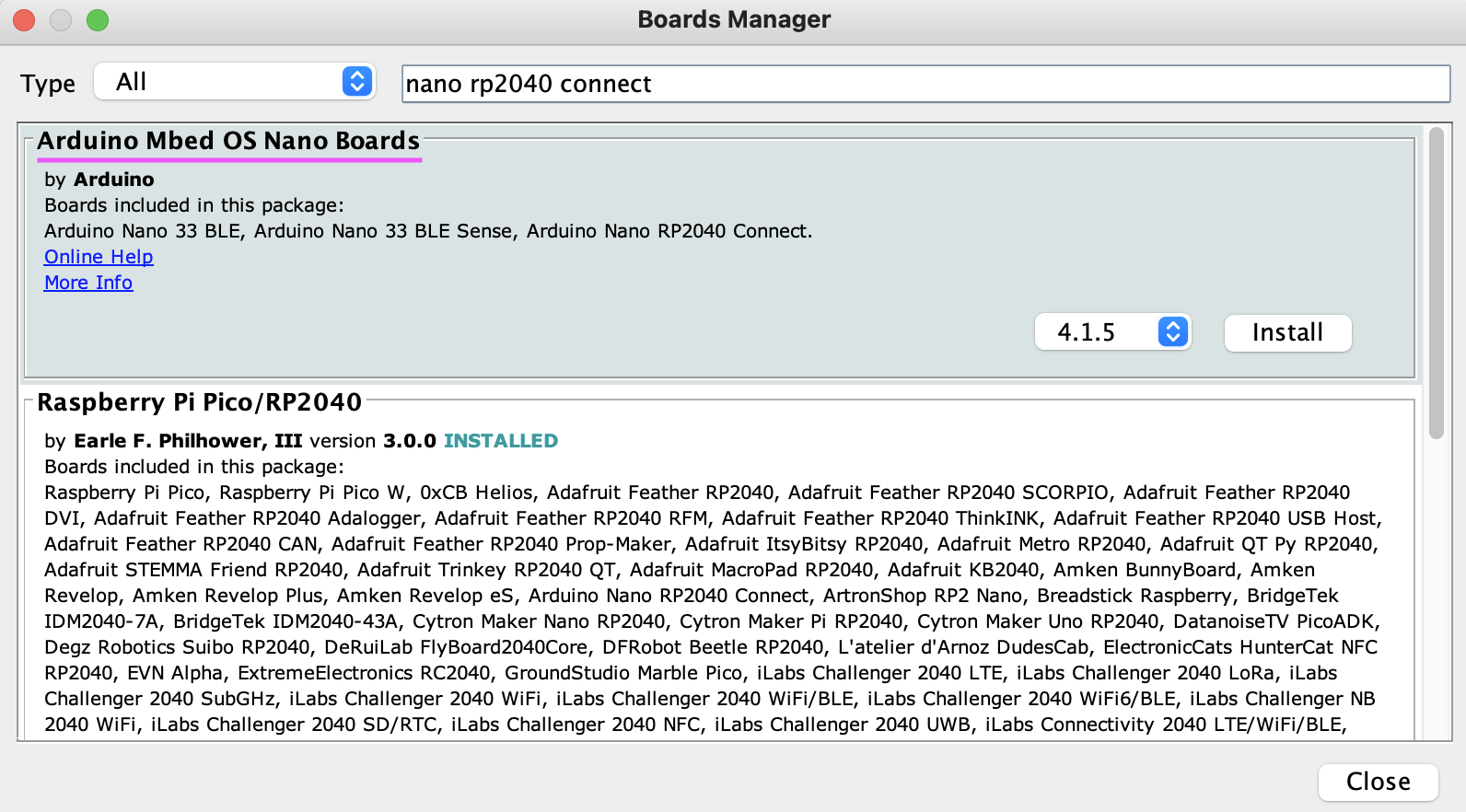
board_manager
/joint_states topic and subscribes to the /gripper/gripper_cmd and /arm/follow_joint_trajectory topics.
Launch ROS 2 Nodes
We should launch the ROS 2 nodes on separate terminals on the Raspberry Pi 5 by executing the following commands step-by-step.-
Launch micro-ROS agent
The micro-ROS agent exposes the publishers and action server running on the Braccio ++ MCU to ROS 2.
-
Launch ei_yolov5_detections node
The
ei_yolov5_detectionsnode detects the objects and publishes the detection results using the Edge Impulse trained model on the OAK-D depth camera.We can check the spatial detection message as follows. -
Launch pick_n_place node
The
pick_n_placenode plans a pick and place operation using MoveIt Task Constructor. MoveIt Task Constructor provides a way to plan for tasks that consist of multiple different subtasks (known as stages as shown in the image below).
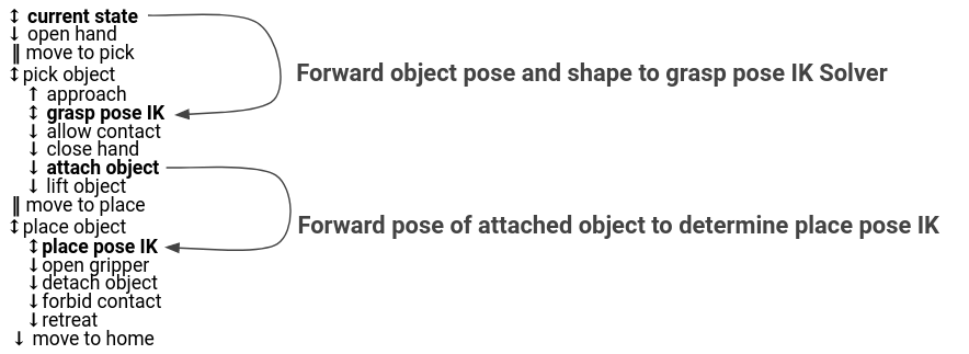
moveit2_task_stages
/ei_yolov5/spatial_detections topic and plans the pick and place operation. While bringing up this node, we need to provide command line parameters for the exact (X, Y, Z) position of the camera in meters from the base of the robot.
robot_state_publisher and move_group nodes to publish the robot model and provide MoveIt 2 actions and services respectively.
-
Launch RViz 2
We can see the real-time motion planning solution execution visualization using the RViz 2.