Introduction
Poor air quality in industrial environments can reduce productivity and raise the risk of accidents. That’s why it’s critical for industrial facilities to regularly evaluate air quality, guaranteeing that their staff is healthy and productive by doing so. Typical Air Quality dimensions that must be monitored include CO, CO2, H2, volatile organic compounds (VOC), and volatile sulphuric compounds, depending on the specific activity that is taking place within the facility. Moreover, managers may ensure that workers stay healthy at work by establishing suitable ventilation systems that reduce outside pollution to levels that are not harmful to employees while still keeping interior settings clean. When stated concentrations surpass a specific level, a traditional Air Quality monitoring system will sound an alarm. The downside of such a system is that it will only react after the threshold is surpassed, warning employees that they have been exposed to the harmful substance for a period of time.
Our Solution
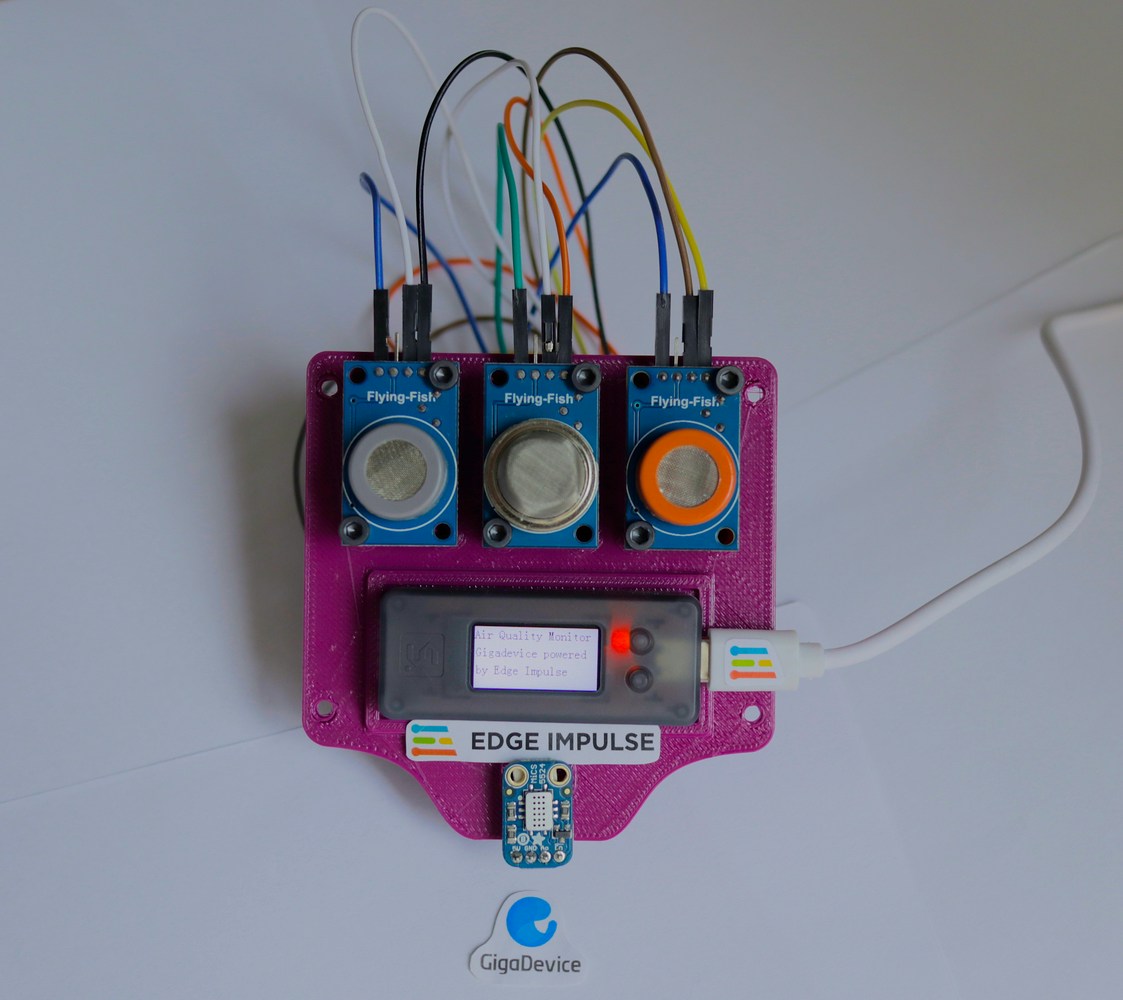
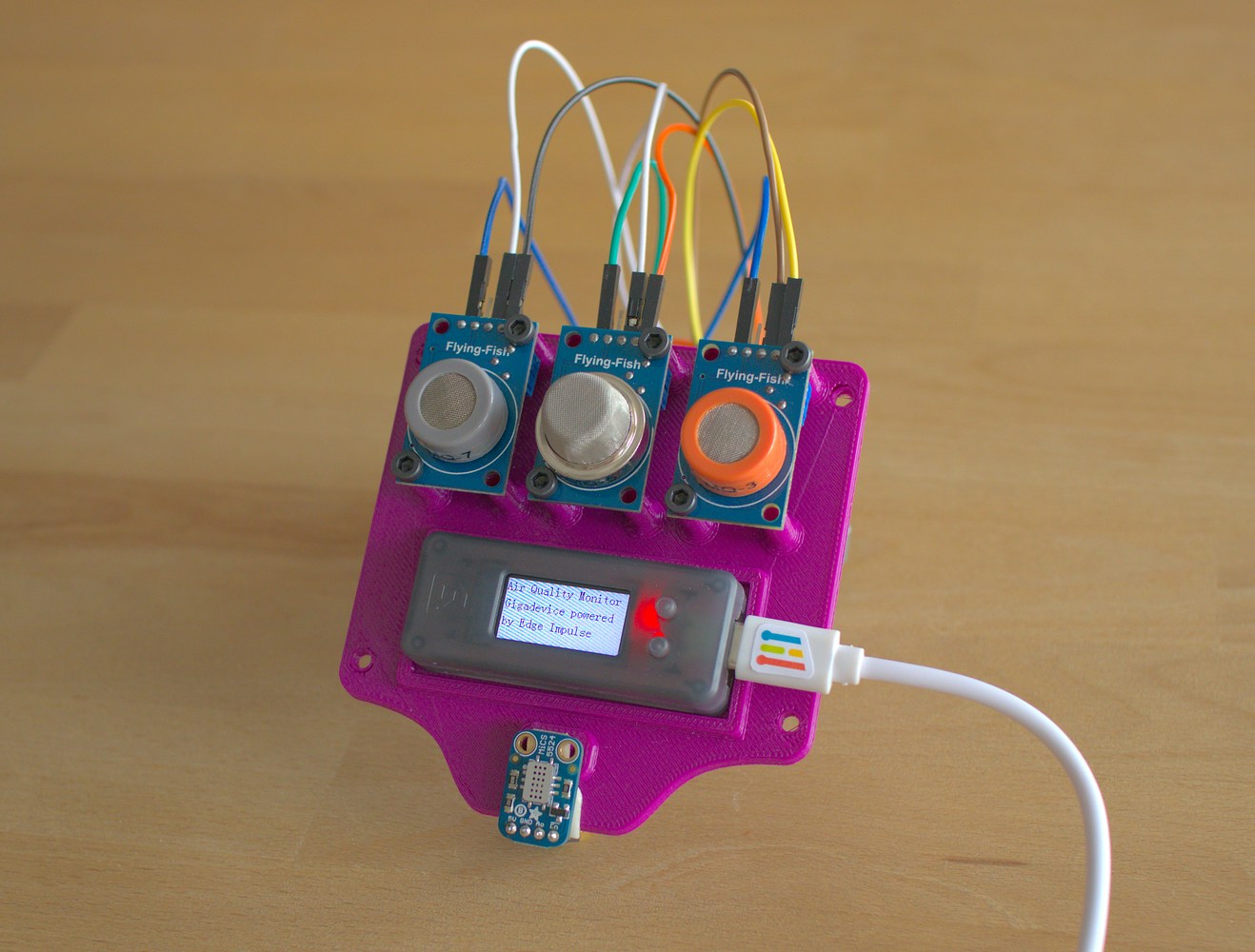
We have developed a prototype that uses a Sipeed Longan Nano V1.1 with a RISC-V Gigadevice microprocessor and gas sensors to detect trends in the variation of air quality dimensions by creating a Machine Learning model in Edge Impulse and deploying it on the device to trigger an alarm if they are headed towards a critical level. This will allow for swift intervention to prevent the air quality from reaching hazardous levels.Hardware Requirements
- SIPEED LONGAN NANO V1.1 - RISC-V
- Adafruit MiCS5524 CO, Alcohol and VOC Gas Sensor Breakout
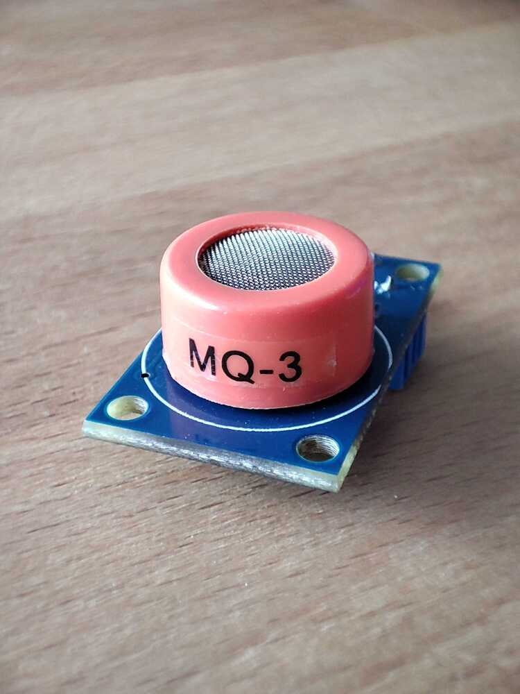
- MQ-3 - Alcohol Sensor
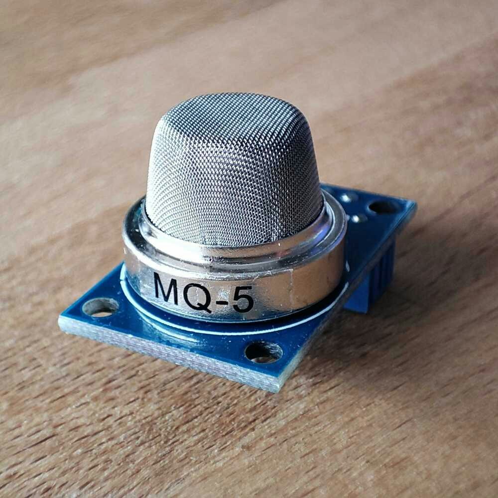
- MQ-5 METHANE GAS SENSOR MODULE
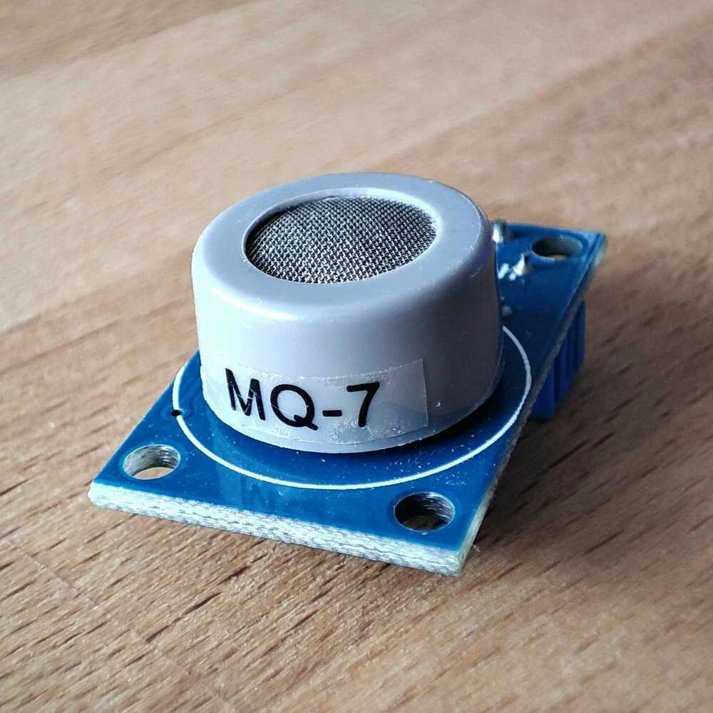
- MQ-7 Gas Sensor - Carbon Monoxide
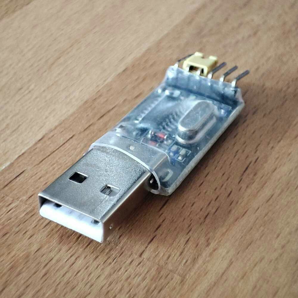
- USB to TTL Serial Cable
Software Requirements
- Edge Impulse account
- Virtual Studio Code with PlatformIO addon
- Edge Impulse CLI
- Udev rule ( for Linux Users)
Hardware Setup
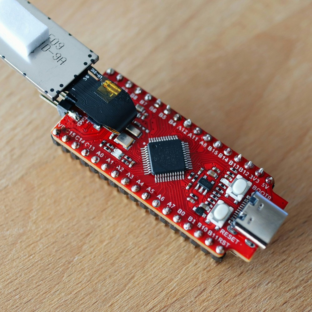
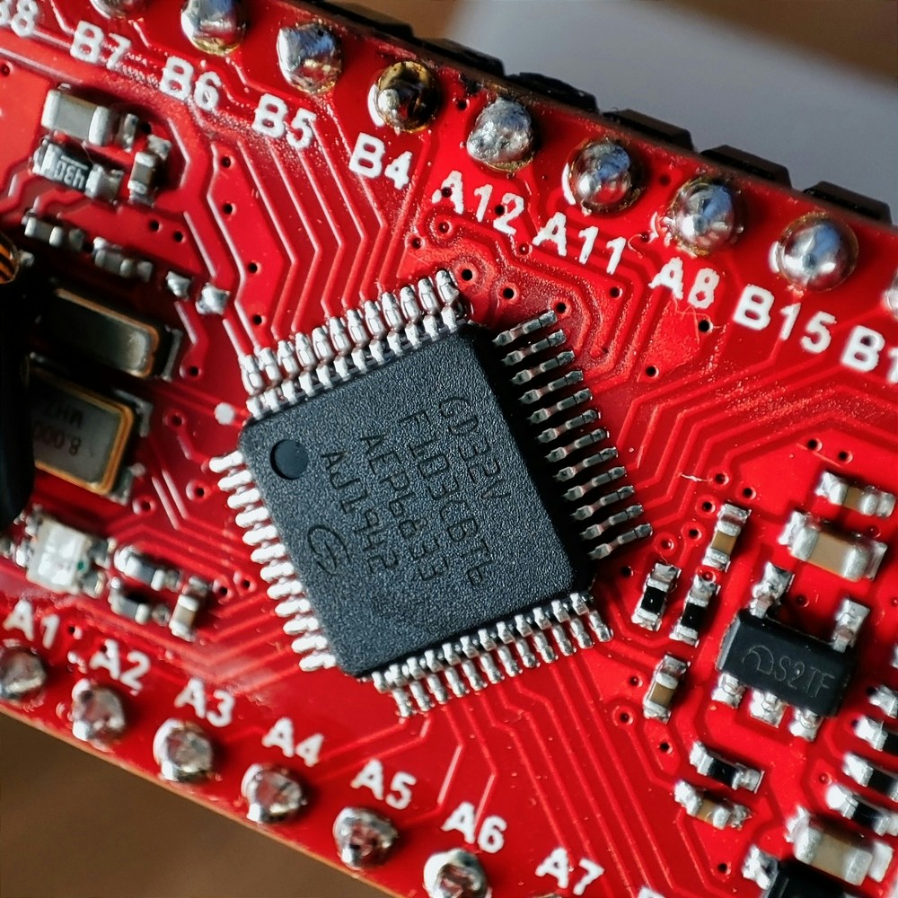
The Sipeed Longan Nano v1.1 is an updated development board based on the Gigadevices GD32VF103CBT6 MCU chip. The board has a built-in 128KB Flash and 32KB SRAM, providing ample space for students, engineers, and geek enthusiasts to tinker with the new-generation RISC-V processors. The board also features a micro USB port, allowing users to easily connect the board to their computer for programming and debugging. In addition, the board has an on-board JTAG interface, making it easy to work with various development tools. Overall, the Sipeed Longan Nano v1.1 is a convenient and affordable option for those who want to explore the world of RISC-V processors. Besides the programming ports and IOs, the development board includes two user-customizable buttons and a small screen making debugging and real-time information really easy to show locally. The GD32VF103 is a 32-bit general-purpose microcontroller based on a RISC-V core that offers an excellent blend of processing power, low power consumption, and peripheral set. This device operates at 108 MHz with zero wait states for Flash accesses to achieve optimum efficiency. It has 128 KB of on-chip Flash memory and 32 KB of SRAM memory. Two APB buses link a wide range of improved I/Os and peripherals. The device has up to two 12-bit ADCs, two 12-bit DACs, four general 16-bit timers, two basic timers, as well as standard and advanced communication interfaces: up to three SPIs, two I2Cs, three USARTs, two UARTs, two I2Ss, two CANs, and a USBFS. An Enhancement Core-Local Interrupt Controller (ECLIC), SysTick timer, and additional debug features are also intimately tied with the RISC-V processor core. The gadgets require a 2.6V to 3.6V power source and can function in temperatures ranging from –40°C to +85 °C. Several power-saving modes allow for the optimization of wakeup latency and power consumption, which is an important factor when creating low-power applications. The GD32VF103 devices are well-suited for a broad range of linked applications, particularly in industrial control, motor drives, power monitor and alarm systems, consumer and portable equipment, POS, vehicle GPS, LED display, and so on. Features- Memory configurations are flexible, with up to 128KB on-chip Flash memory and up to 32KB SRAM memory.
- A wide range of improved I/Os and peripherals are linked to two APB buses.
- SPI, I2C, USART, and I2S are among the many conventional and sophisticated communication interfaces available.
- Two 12-bit 1Msps ADCs with 16 channels, four general-purpose 16-bit timers, and one PWM advanced timer are included.
- Three power-saving modes optimize wakeup latency and energy usage for low-power applications.
Sensors
Gas sensors are electronic devices that detect and identify different types of gasses. There are a few different ways that gas sensors work but the most common type of gas sensor uses electrochemical cells. This type of sensor creates a small voltage when it comes into contact with certain gasses which is then used to identify the presence and concentration of the gas. The MQ gas sensor series are based on the Metal Oxide Semiconductor (MOS) technology, and they function by measuring the change in electrical resistance of a metal oxide film when it is exposed to certain gasses. They have been used by makers for quite a while now, and that is advantageous because they are easy to read (most of the time just an analog pin will suffice) and the options of tracked gasses are quite diverse. Here are the variants we found so far, so you can mix and match them for your own use case:Adafruit MiCS5524 CO, Alcohol, and VOC Gas Sensor
The MiCS-5524 SGX Sensortech is a robust MEMS sensor for detecting indoor carbon monoxide and natural gas leaks, as well as indoor air quality monitoring, breath checker, and early fire detection. This sensor detects CO (1-1000 ppm), Ammonia (1-500 ppm), Ethanol (10-500 ppm), H2 (1-1000 ppm), and Methane/Propane/Iso-Butane (1,000++ ppm), but it cannot tell which gas it has identified. When gasses are identified, the analog voltage rises in accordance with the amount of gas detected. When turned on, the heater consumes around 25-35mA. To save energy, use the EN pin to turn it off (bring it high to 5V to switch off). Simply wait for a second after turning on the heater to ensure that it is fully heated before obtaining readings.MQ-3 Alcohol Sensor
This sensor can detect Alcohol, Benzine, Methane (CH4), Hexane (C₆H₁₄), Liquefied Petroleum Gas (LPG), and Carbon Monoxide (CO), but it has a much higher sensitivity to alcohol than to Benzine.MQ-5 Methane Gas Sensor Module
This sensor can detect Hydrogen (H2), Liquefied Petroleum Gas (LPG), Methane (CH4), Carbon Monoxide (CO), and Alcohol.MQ-7 Carbon Monoxide Sensor
This sensor can detect Carbon Monoxide (CO).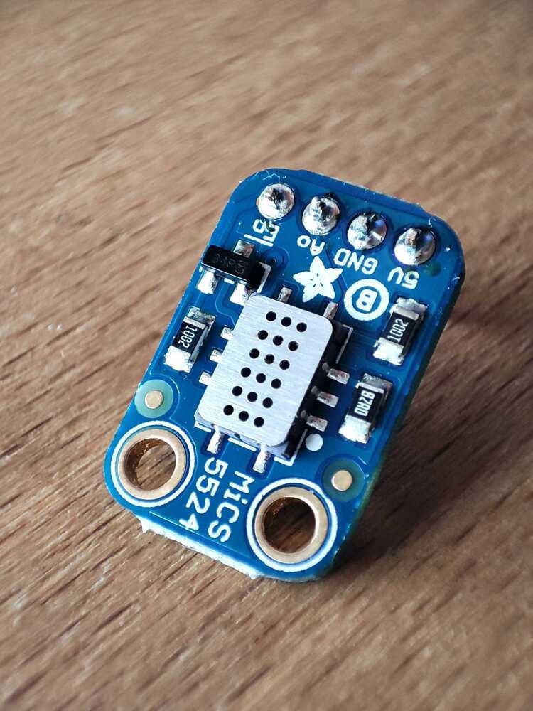
Wiring
All of the sensors map the concentration of the measured gasses to an analog voltage and have to be powered from 3.3 VDC. The following table presents the wiring connections and the schematic depicts the pinout of the Sipeed Longan Nano V1.1. Sensors —> Board GND (all sensors) —> GND VCC (all sensors) —> 3.3V AO (MQ-3) —> PB1 AO (MQ-5) —> PA7 AO (MQ-8) —> PB0 AO (MiCS 5524) —> PA6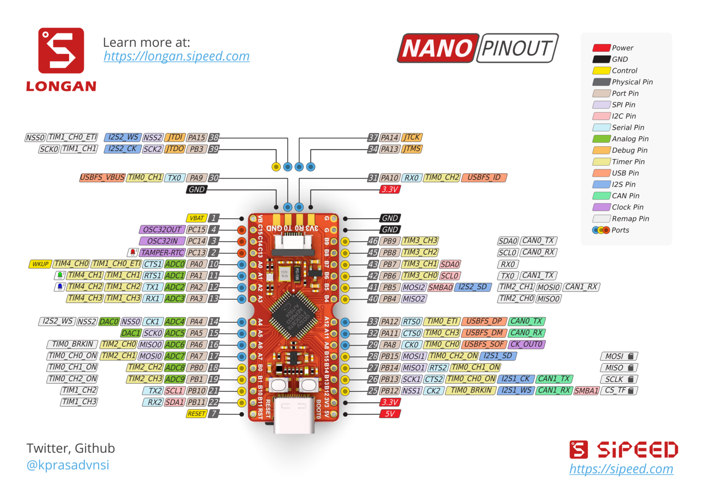
Software Setup
Edge Impulse CLI Installation
The Edge Impulse CLI is a suite of tools that enables you to control local devices, synchronize data for devices without an internet connection, and most importantly, collect data from a device over a serial connection and forward it to the Edge Impulse Platform. Edge Impulse provides comprehensive official documentation regarding the installation process of the Edge Impulse CLI tools. Let’s move on to setting up our development environment.PlatformIO Configuration
To program the Sipeed Longan Nano development board we will employ the PlatformIO addon for VS Code, an open-source ecosystem for IoT development. It includes a cross-platform build system, a package manager, and a library manager. It is used to develop applications for various microcontrollers, including the Arduino, ESP8266, Raspberry Pi, and, relevant for our use case, Gigadevice. PlatformIO is released under the permissive Apache 2.0 license, and it is available for a variety of operating systems, including Windows, macOS, and Linux.- Install Visual Studio Code: https://code.visualstudio.com
- Open VSCode, go to Extensions (on the left menu), search for PlatformIO IDE, and install the plugin. Wait for the installation to complete and restart VSCode.
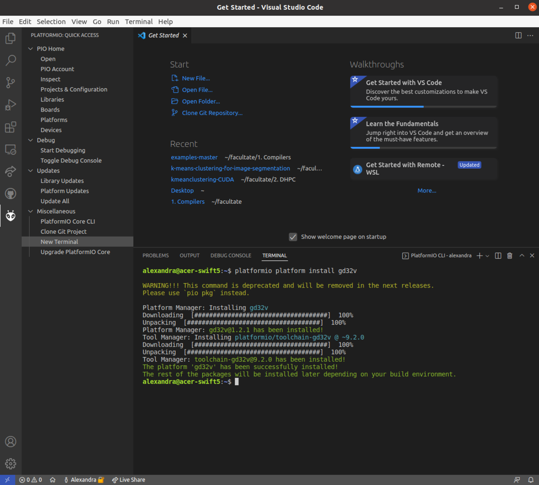
- Install the GD32V platform definition - click on the PlatformIO logo on the left, click on New Terminal at the bottom left, and execute the following installation command in the terminal window:
udev rules for PlatformIO supported boards/devices. You can find a comprehensive guide about how to do that in the official PlatformIO documentation.
Data Acquisition Firmware
With PlatformIO set up, clone the following GitHub repository in your default projects folder. Click on Files, Open folder, select LonganAnalogRead and open it. To program the Longan Nano, we have used an Arduino Framework branched off from the official Sipeed documentation, developed and maintained by scpcom, available on GitHub.picocom -b 115200 -r -l /dev/ttyUSB0
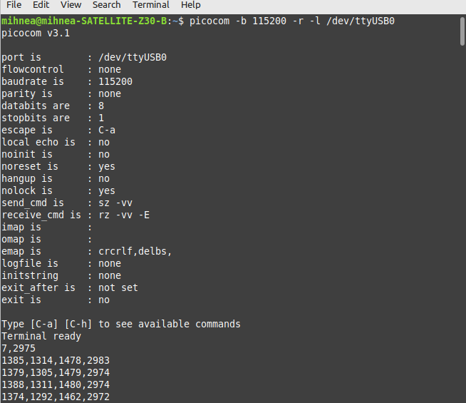
dmesg | grep tty
After we see a properly formatted output in the serial terminal, we must forward it to the Edge Impulse platform.
Creating an Edge Impulse Project
The first step towards building your TinyML Model is creating a new Edge Impulse Project. Be sure to give it a recognizable name, select Developer as your project type, and click on Create new project.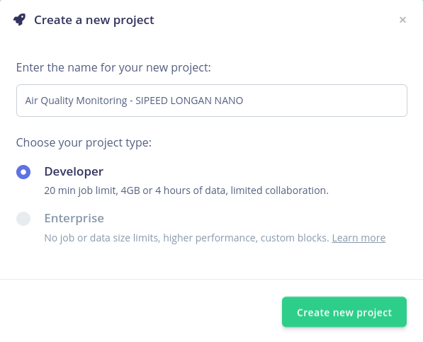
Forwarding Data via Serial Communication
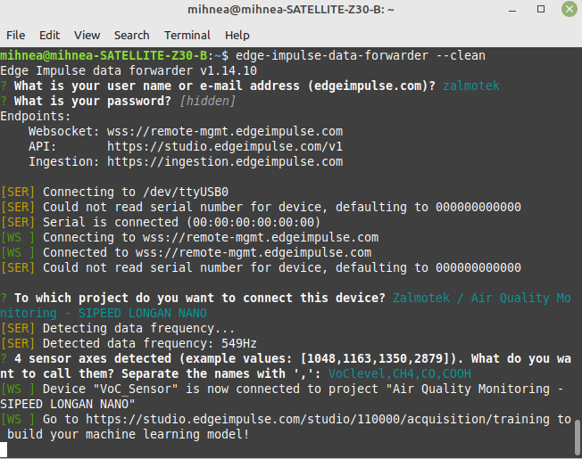
To assign the device to the newly created Edge Impulse project, run the following command:edge-impulse-data-forwarder -clean
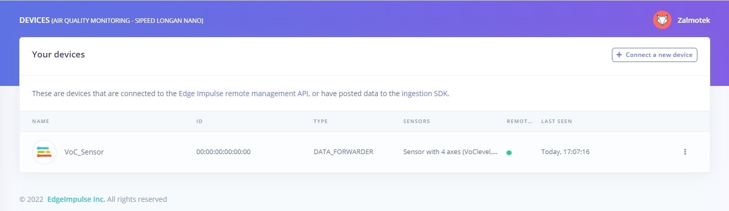
You will be prompted to fill in the email address and password used to access your Edge Impulse account. The CLI will auto-detect the data frequency and then prompt you to name the sensor axes, corresponding to each measurement and then give a fitting name to the device.
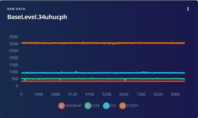
Acquiring Training Data
For this particular use case, we will be training a model to detect 2 dangerous situations that may occur in an automobile painting facility: an alcohol leakage and a methane gas leakage. Both of those can be dangerous and hazardous to employees’ health. Navigate to the Data Acquisition screen. Notice that on the right side of the screen the device is present, with the 4 axes we have previously defined in the terminal and the auto-detected data acquisition frequency. Select a sample length of 10 seconds, give the label a name, and Start sampling. When building the dataset, keep in mind that machine learning leverages data, so when creating a new class (defined by a label), try to record at least 2-3 minutes of data.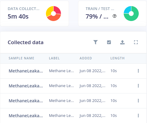
Designing an Impulse
After the data collection phase is over, the next step is to create an Impulse. An Impulse takes raw data from your dataset, divides it into digestible chunks called “windows,” extracts features using signal processing blocks, and then uses the learning block to classify new data. For this application, we are going to use a 1 second window, at a data acquisition frequency of 10 Hz and with the Zero-pad data option checked. We will be using a Flatten processing block, that is fitting for slow-moving averages and a Classification (Keras) as a learning block.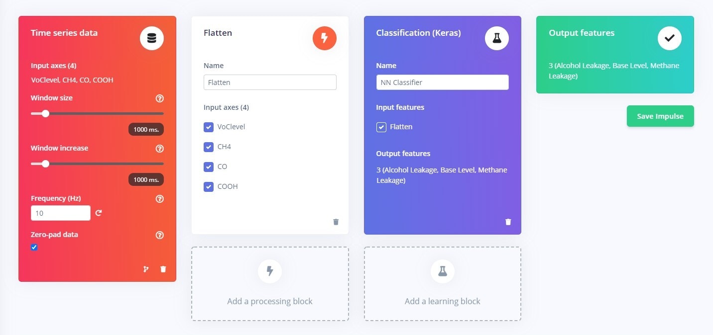
Configuring the Flatten DSP Block
Configuring the Flatten block is a straightforward procedure. Leave all the methods checked and the scale axes to default 1 and click on Save Parameters. Fundamentally, what the Flatten block does is, if the value of Scale Axes is less than 1, the Flatten block rescales the signal’s axes first. Then, depending on the number of methods chosen, statistical analysis is done on each window, computing between 1 and 7 characteristics for each axis.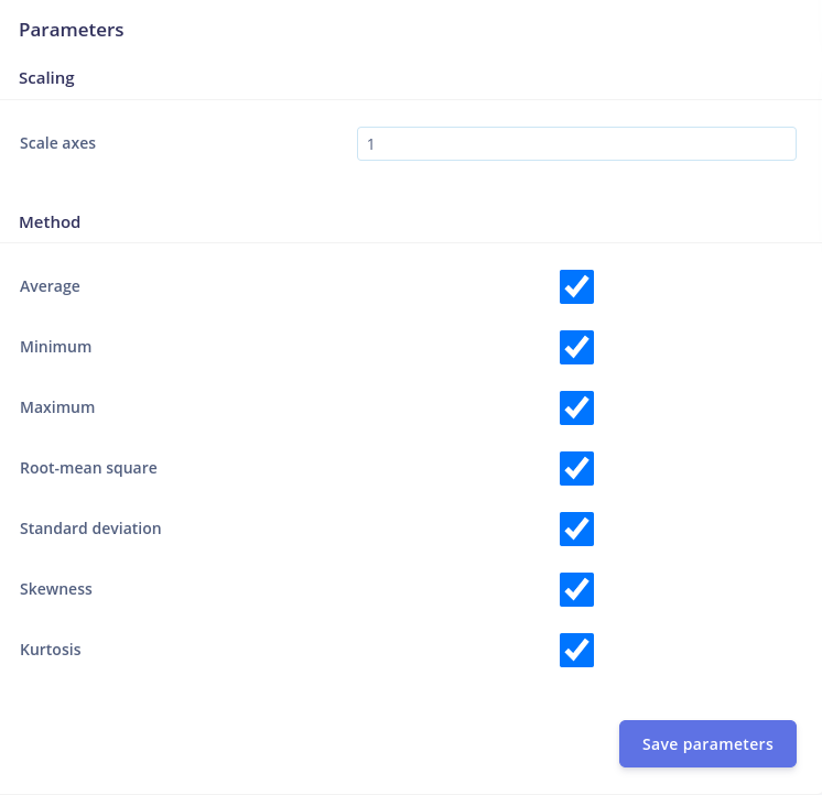
Configure the NN Classifier Learning Block
Under the Impulse Design menu, the NN Classifier tab allows us to define several parameters that influence the neural network’s training process. For the time being, the Training setting can be left at its default value. Click on the Start Training button and notice how the training process is assigned to a processing cluster.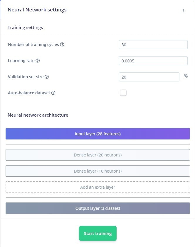
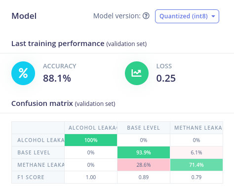
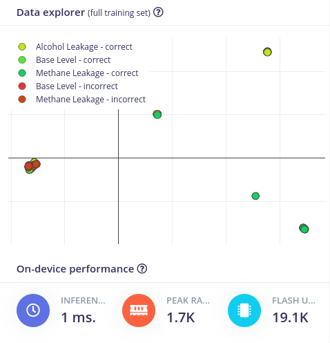
Model Testing
A great way of going about testing our model is to navigate to the Model Testing tab. You will be presented with the samples stored in the Testing data pool. Click on Classify all to run all this data through your Impulse. The Model testing tab provides the user the ability to test out and optimize the model before going through the effort of deploying it back on the edge. The possibility of going back and adding Training data, tweaking the DSP and Learning block, and fine-tuning the model shaves off an enormous amount of development time when creating an edge computing application.Deploying the Model as Arduino Library
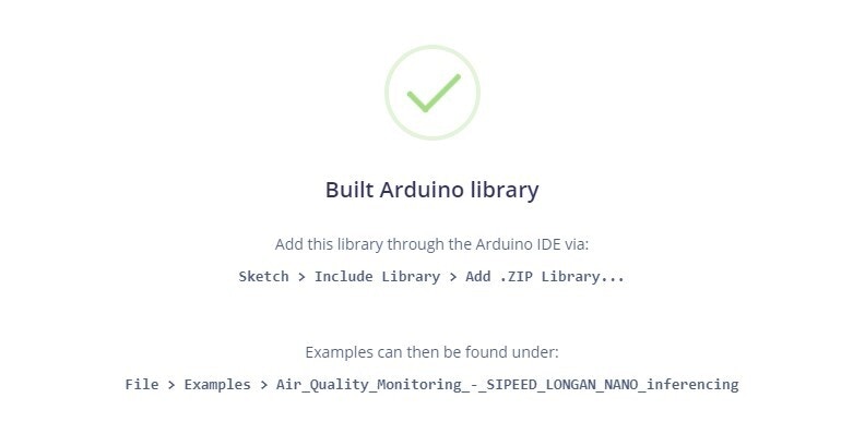
Once you are happy with the performance of the TinyML model, it’s time to deploy it back on the edge. Navigate to the Deployment tab, select Arduino library, and click Build.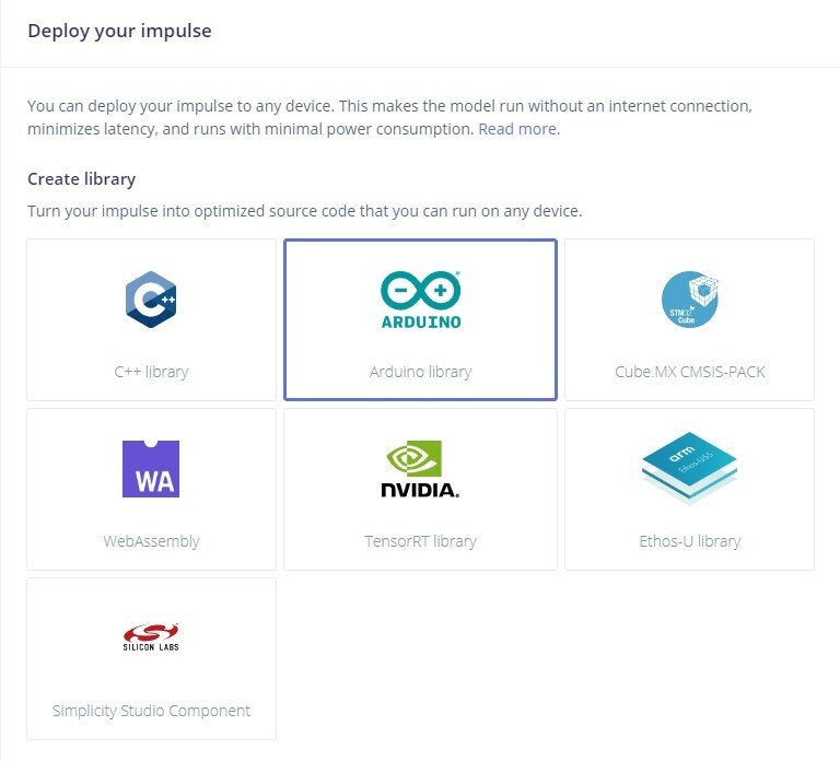
libs folder of your PlatformIO project.
Conclusion
By selecting the proper sensors for your use case and training the model accordingly, you may develop an accurate bespoke gas tracker using the methods mentioned above. The Gigadevice processor is a powerhouse, and we believe it is underutilized in this application. However, given the price and capabilities of the development board, it is a good buy, with room to grow for other applications as RISC-V processors gain popularity in industry, academia, and among hobbyists. While gas sensors are important for ensuring safety in confined spaces and for reducing environmental pollution they have many other places where they can be used besides industry. In the home, gas sensors can be used to detect leaks and to improve energy efficiency. In transportation, gas sensors can be used to monitor engine performance and to reduce emissions. In the wild they can be used to prevent wildfires as a part of an early detection system. The sensors are placed in an area and monitor the air for combustible gasses.