> ## Documentation Index
> Fetch the complete documentation index at: https://docs.edgeimpulse.com/llms.txt
> Use this file to discover all available pages before exploring further.
# Visual Inspection station for PCBs
> Edge AI Vision Inspection System: Transforming a $60 Single Board Computer into an Industrial Inspection Station
Created By: Mukesh Sankhla
Public Project Links:
* [Slot Occupancy Detection](https://studio.edgeimpulse.com/public/1123393/live)
* [PCB Defect Inspection](https://studio.edgeimpulse.com/public/1125264/live)
* [PCBA Big Component Inspection](https://studio.edgeimpulse.com/public/1125284/live)
* [PCBA Small Component Inspection](https://studio.edgeimpulse.com/public/1125307/live)
GitHub Repo: [https://github.com/MukeshSankhla/Edge-Ai-Vision-Inspection](https://github.com/MukeshSankhla/Edge-Ai-Vision-Inspection)
CAD Design (Fusion 360): [Enclosure & Turntable Model](https://a360.co/4xOSRFz)
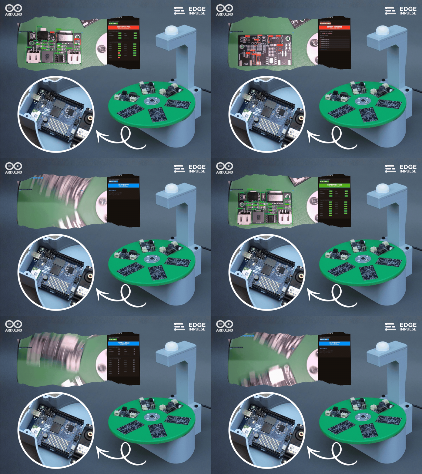 What if a \$60 single board computer could turn a simple webcam into a complete industrial vision inspection system? That was the idea behind this project. At the heart of the system is the Arduino UNO Q, a compact Linux-capable single-board computer that brings enough processing power to run modern AI workloads at the edge. Combined with Edge Impulse, it becomes possible to take computer-vision models developed on a PC and bring them directly onto an embedded device for real-time inspection—without relying on the cloud.
For this project, I built a six-slot rotating vision inspection station using the Arduino UNO Q, a webcam, and a servo motor. A board placed into one of the six slots is automatically rotated into the inspection position, where the camera captures it and the AI pipeline determines what is present and what needs to be inspected. The system first identifies whether the slot is empty, contains a bare PCB, or contains an assembled PCBA:
* **Bare PCBs** are inspected for scratches and visible surface damage.
* **Assembled PCBAs** go through component-Slevel inspection, verifying both large components (USB-C, JST connectors, switches, power ICs, inductors) and smaller 0805 components (LEDs, resistors, capacitors).
The interesting part is that the AI models were trained separately using **YOLO** and then brought into **Edge Impulse using Bring Your Own Model (BYOM)**. Edge Impulse essentially becomes the bridge between model development and deployment—it packages the models, manages the edge inference pipeline, and makes it much easier to deploy and run the vision workload directly on the UNO Q. The result is a small, self-contained inspection station combining AI vision, robotics, and edge computing into one system.
What started as an experiment with a camera, a rotating platform, and an Arduino UNO Q turned into a miniature automated quality-inspection line—the kind of system that can continuously look at physical products, make decisions locally, and trigger the next action without needing a human to inspect every board.
## Training the Machine Learning Models
As mentioned earlier, for this project I am using a custom battery charging and discharging circuit PCB, but the same approach can be applied to almost any PCB or PCBA depending on your inspection requirements.
The first step is to build the dataset for each of the four vision models. Since the final system will use the same webcam and camera position, it is important to capture the training images using the same camera and setup that will be used during the actual inspection. I connected the webcam to my PC, opened the Camera app, and captured multiple images of the different inspection conditions. I captured images of an empty slot, bare PCB, and assembled PCBA, along with different examples of the defects and components that I wanted the models to learn. In general, having more representative images for each condition gives the model more examples to learn from and can help improve its ability to generalize.
What if a \$60 single board computer could turn a simple webcam into a complete industrial vision inspection system? That was the idea behind this project. At the heart of the system is the Arduino UNO Q, a compact Linux-capable single-board computer that brings enough processing power to run modern AI workloads at the edge. Combined with Edge Impulse, it becomes possible to take computer-vision models developed on a PC and bring them directly onto an embedded device for real-time inspection—without relying on the cloud.
For this project, I built a six-slot rotating vision inspection station using the Arduino UNO Q, a webcam, and a servo motor. A board placed into one of the six slots is automatically rotated into the inspection position, where the camera captures it and the AI pipeline determines what is present and what needs to be inspected. The system first identifies whether the slot is empty, contains a bare PCB, or contains an assembled PCBA:
* **Bare PCBs** are inspected for scratches and visible surface damage.
* **Assembled PCBAs** go through component-Slevel inspection, verifying both large components (USB-C, JST connectors, switches, power ICs, inductors) and smaller 0805 components (LEDs, resistors, capacitors).
The interesting part is that the AI models were trained separately using **YOLO** and then brought into **Edge Impulse using Bring Your Own Model (BYOM)**. Edge Impulse essentially becomes the bridge between model development and deployment—it packages the models, manages the edge inference pipeline, and makes it much easier to deploy and run the vision workload directly on the UNO Q. The result is a small, self-contained inspection station combining AI vision, robotics, and edge computing into one system.
What started as an experiment with a camera, a rotating platform, and an Arduino UNO Q turned into a miniature automated quality-inspection line—the kind of system that can continuously look at physical products, make decisions locally, and trigger the next action without needing a human to inspect every board.
## Training the Machine Learning Models
As mentioned earlier, for this project I am using a custom battery charging and discharging circuit PCB, but the same approach can be applied to almost any PCB or PCBA depending on your inspection requirements.
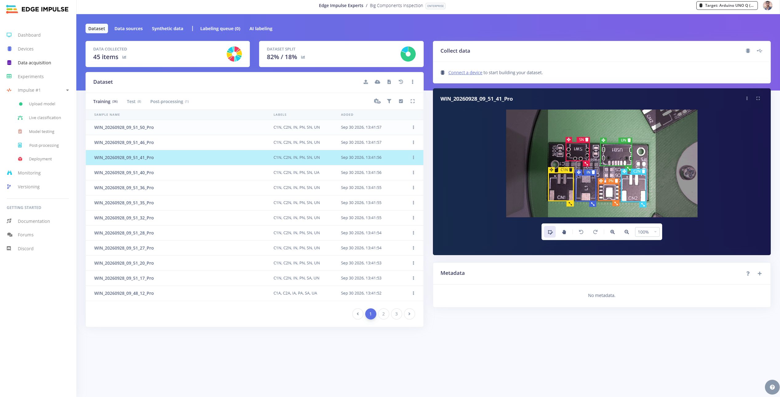
The first step is to build the dataset for each of the four vision models. Since the final system will use the same webcam and camera position, it is important to capture the training images using the same camera and setup that will be used during the actual inspection. I connected the webcam to my PC, opened the Camera app, and captured multiple images of the different inspection conditions. I captured images of an empty slot, bare PCB, and assembled PCBA, along with different examples of the defects and components that I wanted the models to learn. In general, having more representative images for each condition gives the model more examples to learn from and can help improve its ability to generalize.
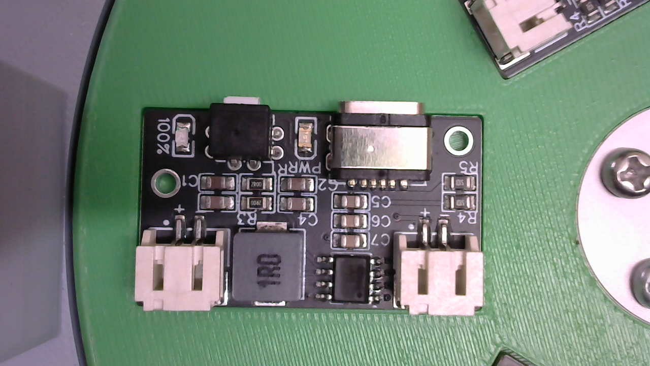
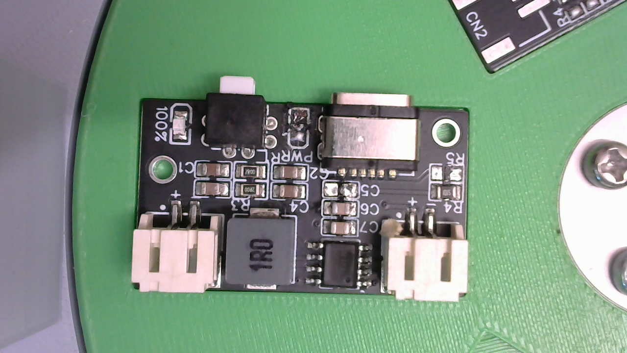
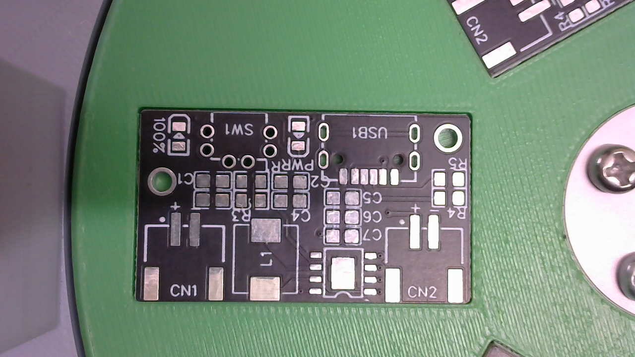
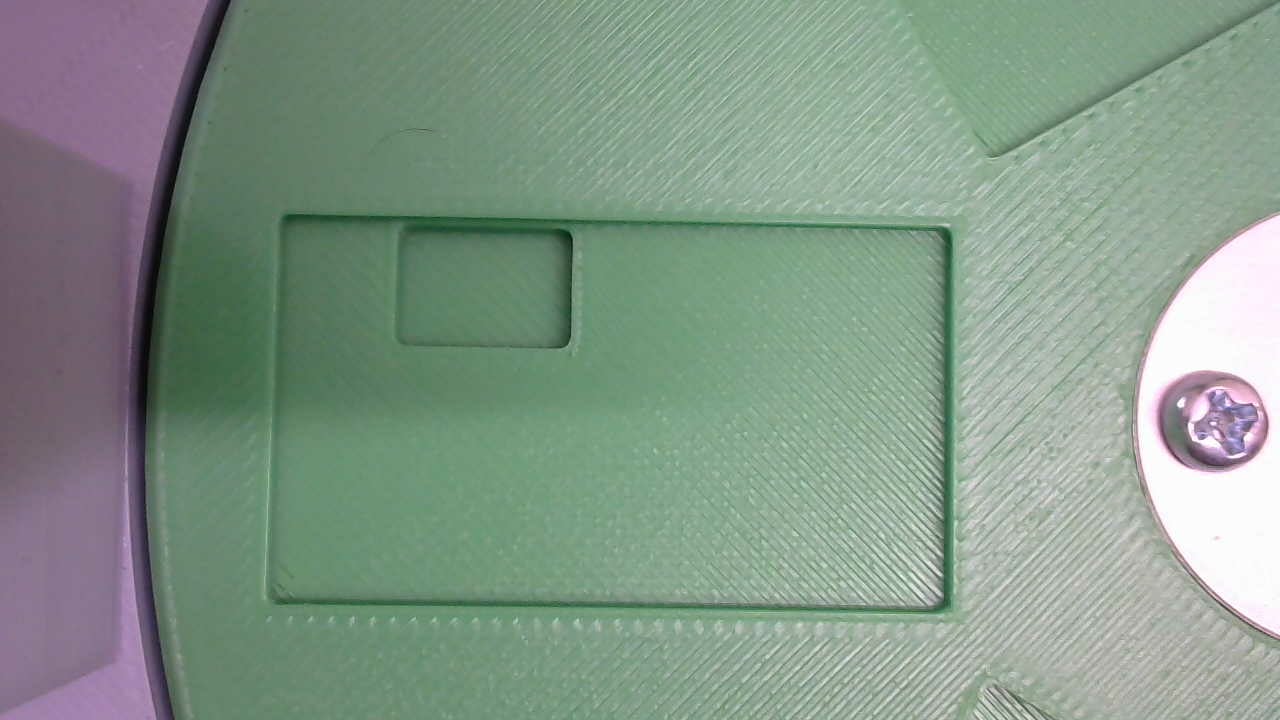 Once the images were collected, I imported the dataset into [Make Sense](https://www.makesense.ai/), an online annotation tool, and started labeling the images according to the requirements of each model.
### Model Classes & Annotations
1. **Slot Occupancy Model (Image Classification):**
* `Empty`
* `PCB`
* `PCBA`
2. **PCB Inspection Model (Object Detection):**
* `Issue / Scratch` — Used to identify visible scratches or damage on the PCB surface.
Once the images were collected, I imported the dataset into [Make Sense](https://www.makesense.ai/), an online annotation tool, and started labeling the images according to the requirements of each model.
### Model Classes & Annotations
1. **Slot Occupancy Model (Image Classification):**
* `Empty`
* `PCB`
* `PCBA`
2. **PCB Inspection Model (Object Detection):**
* `Issue / Scratch` — Used to identify visible scratches or damage on the PCB surface.
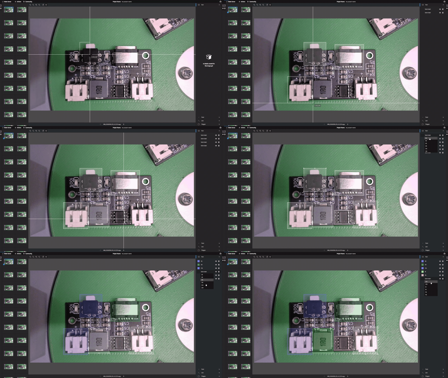 3. **PCBA Big Component Inspection Model (Object Detection):**
Classes based on the component type and whether the component is present (`A` = Available) or missing (`N` = Not Available):
* `SA` / `SN` — SMD Switch Available / Not Available
* `UA` / `UN` — USB Type-C Available / Not Available
* `C1A` / `C1N`, `C2A` / `C2N` — JST Connector 1/2 Available / Not Available
* `IA` / `IN` — Inductor Available / Not Available
* `PA` / `PN` — Power IC Available / Not Available
3. **PCBA Big Component Inspection Model (Object Detection):**
Classes based on the component type and whether the component is present (`A` = Available) or missing (`N` = Not Available):
* `SA` / `SN` — SMD Switch Available / Not Available
* `UA` / `UN` — USB Type-C Available / Not Available
* `C1A` / `C1N`, `C2A` / `C2N` — JST Connector 1/2 Available / Not Available
* `IA` / `IN` — Inductor Available / Not Available
* `PA` / `PN` — Power IC Available / Not Available
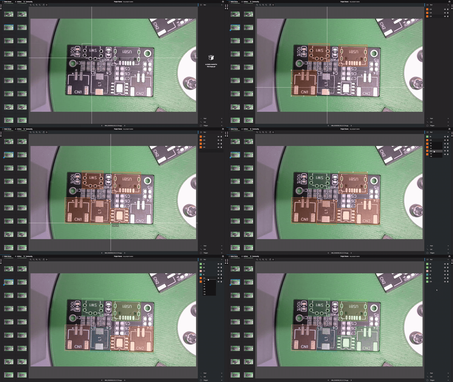 4. **PCBA Small Component Inspection Model (Object Detection for 0805 components):**
* `L1A` / `L1N`, `L2A` / `L2N` — LEDs
* `C1A` / `C1N` through `C7A` / `C7N` — Capacitors
* `R1A` / `R1N`, `R3A` / `R3N`, `R4A` / `R4N`, `R5A` / `R5N` — Resistors
This naming convention makes it easier for the final application to understand not only which component it is looking at, but also whether that component is present or missing.
After annotating all the images, I exported the annotations from Make Sense as a single CSV file. This labeled dataset is then used as the foundation for training the individual machine-learning models.
### Dataset Organization
4. **PCBA Small Component Inspection Model (Object Detection for 0805 components):**
* `L1A` / `L1N`, `L2A` / `L2N` — LEDs
* `C1A` / `C1N` through `C7A` / `C7N` — Capacitors
* `R1A` / `R1N`, `R3A` / `R3N`, `R4A` / `R4N`, `R5A` / `R5N` — Resistors
This naming convention makes it easier for the final application to understand not only which component it is looking at, but also whether that component is present or missing.
After annotating all the images, I exported the annotations from Make Sense as a single CSV file. This labeled dataset is then used as the foundation for training the individual machine-learning models.
### Dataset Organization
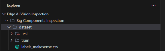 Before moving on to model training, make sure the datasets are organized properly. Since we are training four different models, I recommend keeping each model's dataset completely separate:
```text theme={"system"}
Main Folder/
│
├── Slot Occupancy/
│ └── dataset/
│ ├── training/
│ ├── testing/
│ └── Label.csv
│
├── PCB Inspection/
│ └── dataset/
│ ├── training/
│ ├── testing/
│ └── Label.csv
│
├── PCBA Big Comp Inspection/
│ └── dataset/
│ ├── training/
│ ├── testing/
│ └── Label.csv
│
└── PCBA Small Comp Inspection/
└── dataset/
├── training/
├── testing/
└── Label.csv
```
Each model has its own dataset folder, containing separate training and testing images along with the corresponding `Label.csv` file. Keeping the four datasets isolated is important because each model has a different purpose and different set of classes.
## Preparing the Dataset for YOLO Training
Once the images have been captured and annotated in MakeSense, the next step is to convert the dataset into the format required by YOLO. The original dataset contains the captured images and the `labels_makesense.csv` annotation file. For the example Big Component Inspection model, the dataset contains 44 images and 264 bounding-box annotations, split into 36 training images and 8 testing images.
The MakeSense annotations are then converted into the standard YOLO dataset structure:
```text theme={"system"}
yolo_dataset/
│
├── images/
│ ├── train/
│ └── val/
│
├── labels/
│ ├── train/
│ └── val/
│
└── data.yaml
```
Before training, run a dataset verification step to make sure the images and annotations are valid. This checks that the bounding boxes are correctly formatted and remain within the valid image boundaries.
> \[!IMPORTANT]
> One critical detail in this project is that the components are mounted in fixed physical positions on the PCB. Because of this, **horizontal and vertical image flipping were disabled during augmentation**. Flipping the image could effectively swap components from one side of the PCB to another and teach the model an incorrect spatial relationship.
## Training & Evaluating the YOLO Model
### Training the YOLO Model
For this project, I used **YOLO11 Nano (`yolo11n.pt`)**, a lightweight object-detection model that is well suited for edge deployment. The model was trained for 80 epochs with an image size of 640 × 640, a batch size of 8, and an NVIDIA RTX 5070 Ti GPU.
The training was executed using:
```bash theme={"system"}
python train.py --epochs 80 --batch 8 --device 0
```
The training process took approximately 48 seconds for 80 epochs on the RTX 5070 Ti. During training, the model learns the visual characteristics of each component and the difference between the Available (A) and Not Available/Missing (N) classes.
Before moving on to model training, make sure the datasets are organized properly. Since we are training four different models, I recommend keeping each model's dataset completely separate:
```text theme={"system"}
Main Folder/
│
├── Slot Occupancy/
│ └── dataset/
│ ├── training/
│ ├── testing/
│ └── Label.csv
│
├── PCB Inspection/
│ └── dataset/
│ ├── training/
│ ├── testing/
│ └── Label.csv
│
├── PCBA Big Comp Inspection/
│ └── dataset/
│ ├── training/
│ ├── testing/
│ └── Label.csv
│
└── PCBA Small Comp Inspection/
└── dataset/
├── training/
├── testing/
└── Label.csv
```
Each model has its own dataset folder, containing separate training and testing images along with the corresponding `Label.csv` file. Keeping the four datasets isolated is important because each model has a different purpose and different set of classes.
## Preparing the Dataset for YOLO Training
Once the images have been captured and annotated in MakeSense, the next step is to convert the dataset into the format required by YOLO. The original dataset contains the captured images and the `labels_makesense.csv` annotation file. For the example Big Component Inspection model, the dataset contains 44 images and 264 bounding-box annotations, split into 36 training images and 8 testing images.
The MakeSense annotations are then converted into the standard YOLO dataset structure:
```text theme={"system"}
yolo_dataset/
│
├── images/
│ ├── train/
│ └── val/
│
├── labels/
│ ├── train/
│ └── val/
│
└── data.yaml
```
Before training, run a dataset verification step to make sure the images and annotations are valid. This checks that the bounding boxes are correctly formatted and remain within the valid image boundaries.
> \[!IMPORTANT]
> One critical detail in this project is that the components are mounted in fixed physical positions on the PCB. Because of this, **horizontal and vertical image flipping were disabled during augmentation**. Flipping the image could effectively swap components from one side of the PCB to another and teach the model an incorrect spatial relationship.
## Training & Evaluating the YOLO Model
### Training the YOLO Model
For this project, I used **YOLO11 Nano (`yolo11n.pt`)**, a lightweight object-detection model that is well suited for edge deployment. The model was trained for 80 epochs with an image size of 640 × 640, a batch size of 8, and an NVIDIA RTX 5070 Ti GPU.
The training was executed using:
```bash theme={"system"}
python train.py --epochs 80 --batch 8 --device 0
```
The training process took approximately 48 seconds for 80 epochs on the RTX 5070 Ti. During training, the model learns the visual characteristics of each component and the difference between the Available (A) and Not Available/Missing (N) classes.
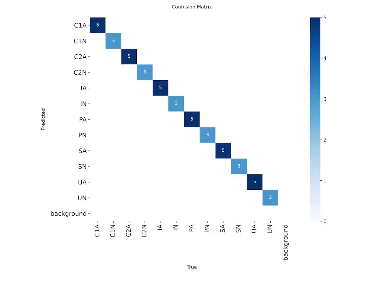
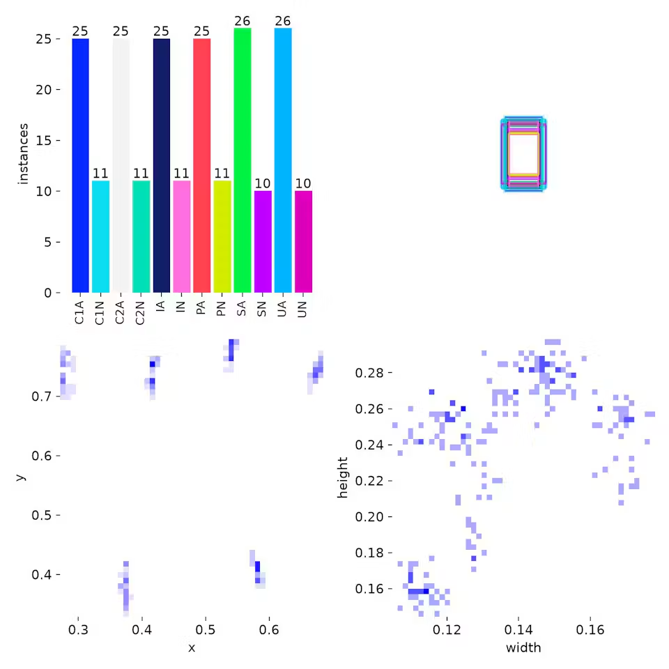
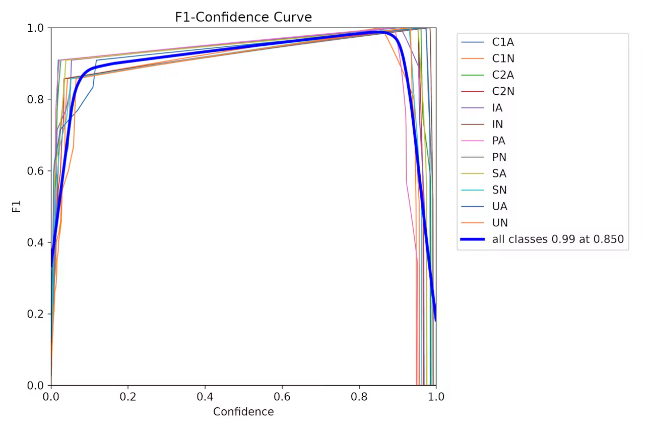
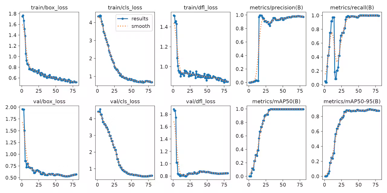
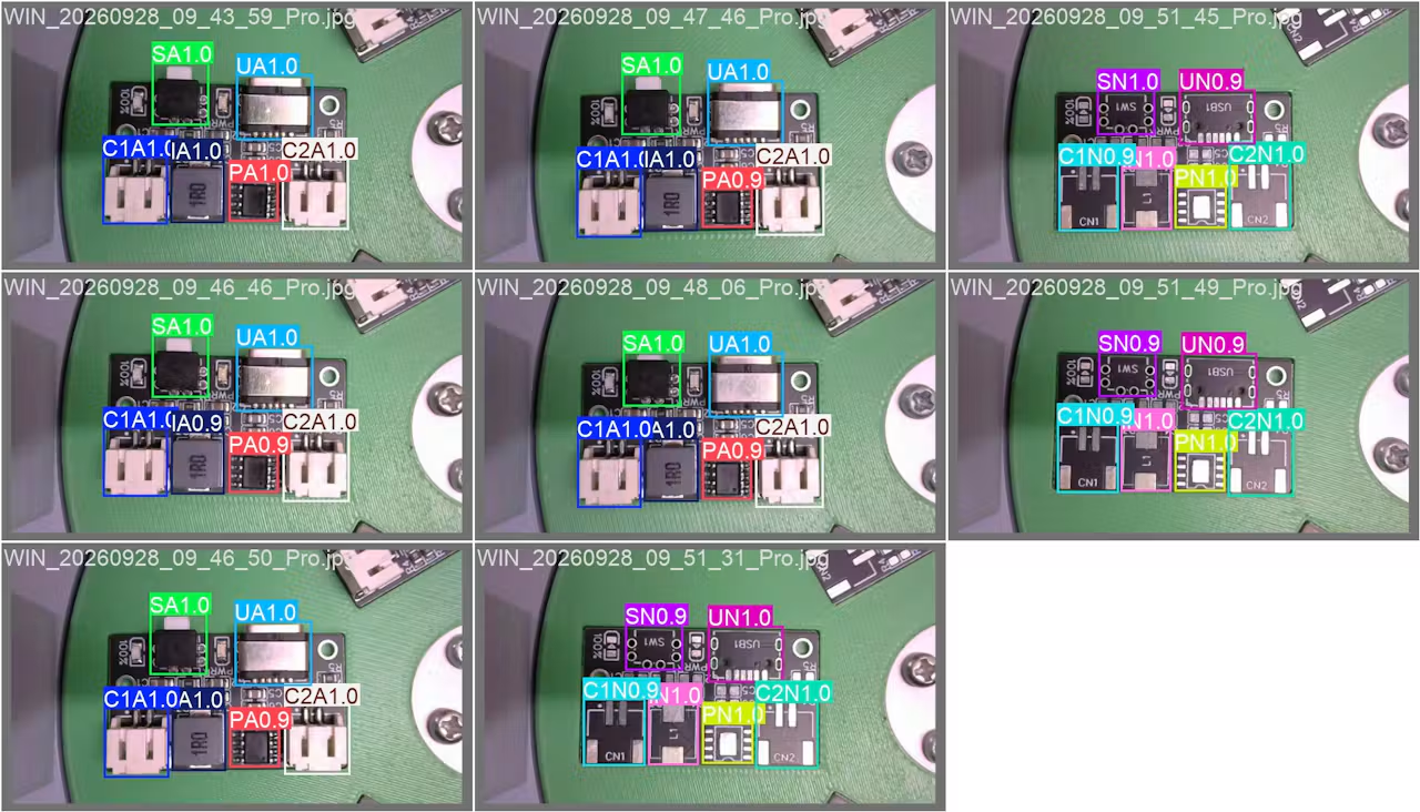 ### Evaluating and Testing the YOLO Model
After training the YOLO model, the next step is to evaluate its performance using the validation dataset.
For the example Big Component Inspection model:
* **Precision:** 97.94%
* **Recall:** 100%
* **mAP\@0.5:** 99.50%
* **mAP\@0.5:0.95:** 89.60%
### Evaluating and Testing the YOLO Model
After training the YOLO model, the next step is to evaluate its performance using the validation dataset.
For the example Big Component Inspection model:
* **Precision:** 97.94%
* **Recall:** 100%
* **mAP\@0.5:** 99.50%
* **mAP\@0.5:0.95:** 89.60%
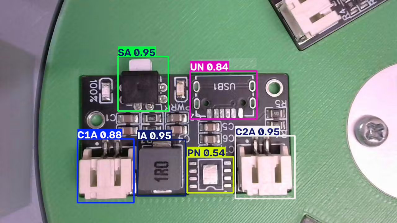
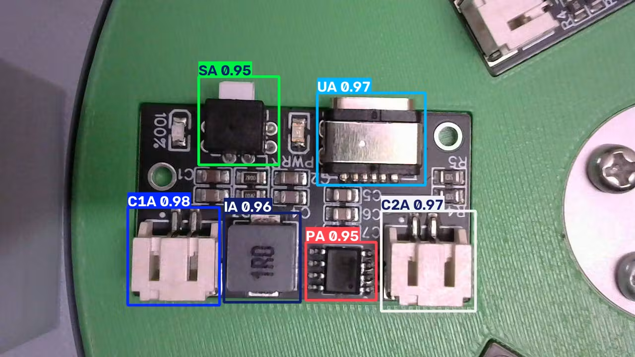
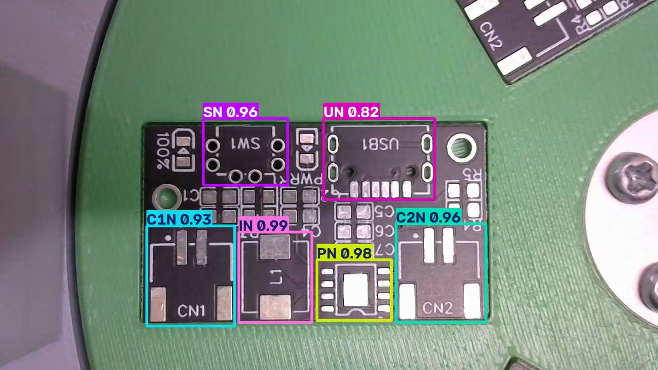 After checking the numerical metrics, I also performed test inference on the images to visually verify the detections. The model correctly identified all six large components on fully populated boards and classified the corresponding components as missing on bare/unpopulated boards. Visual verification confirms that bounding boxes are correctly positioned and that the model detects the expected components before moving to deployment.
## Exporting the YOLO Model to ONNX
Once the YOLO model has been trained and tested successfully, the next step is to export the best model into ONNX (Open Neural Network Exchange) format:
* **Saved Path:** `runs/train/weights/best.onnx`
* **Model Size:** \~10.1 MB
* **Opset Version:** 17/18
* **Graph Optimization:** Optimized using `onnxslim` to reduce unnecessary overhead while keeping the trained model intact.
* **Input Shape:** `[1, 3, 640, 640]` in `float32` format.
* **Output Shape:** `[1, 16, 8400]`, containing bounding-box coordinates and confidence scores for the 12 large-component classes.
* **Inference Speed:** \~3.2 ms per image in ONNX Runtime.
## Importing the YOLO Model into Edge Impulse (BYOM)
The same training process is followed for the other inspection models. Once the models are exported to ONNX, we bring them into Edge Impulse using Bring Your Own Model (BYOM).
### Creating the Edge Impulse Project
After checking the numerical metrics, I also performed test inference on the images to visually verify the detections. The model correctly identified all six large components on fully populated boards and classified the corresponding components as missing on bare/unpopulated boards. Visual verification confirms that bounding boxes are correctly positioned and that the model detects the expected components before moving to deployment.
## Exporting the YOLO Model to ONNX
Once the YOLO model has been trained and tested successfully, the next step is to export the best model into ONNX (Open Neural Network Exchange) format:
* **Saved Path:** `runs/train/weights/best.onnx`
* **Model Size:** \~10.1 MB
* **Opset Version:** 17/18
* **Graph Optimization:** Optimized using `onnxslim` to reduce unnecessary overhead while keeping the trained model intact.
* **Input Shape:** `[1, 3, 640, 640]` in `float32` format.
* **Output Shape:** `[1, 16, 8400]`, containing bounding-box coordinates and confidence scores for the 12 large-component classes.
* **Inference Speed:** \~3.2 ms per image in ONNX Runtime.
## Importing the YOLO Model into Edge Impulse (BYOM)
The same training process is followed for the other inspection models. Once the models are exported to ONNX, we bring them into Edge Impulse using Bring Your Own Model (BYOM).
### Creating the Edge Impulse Project
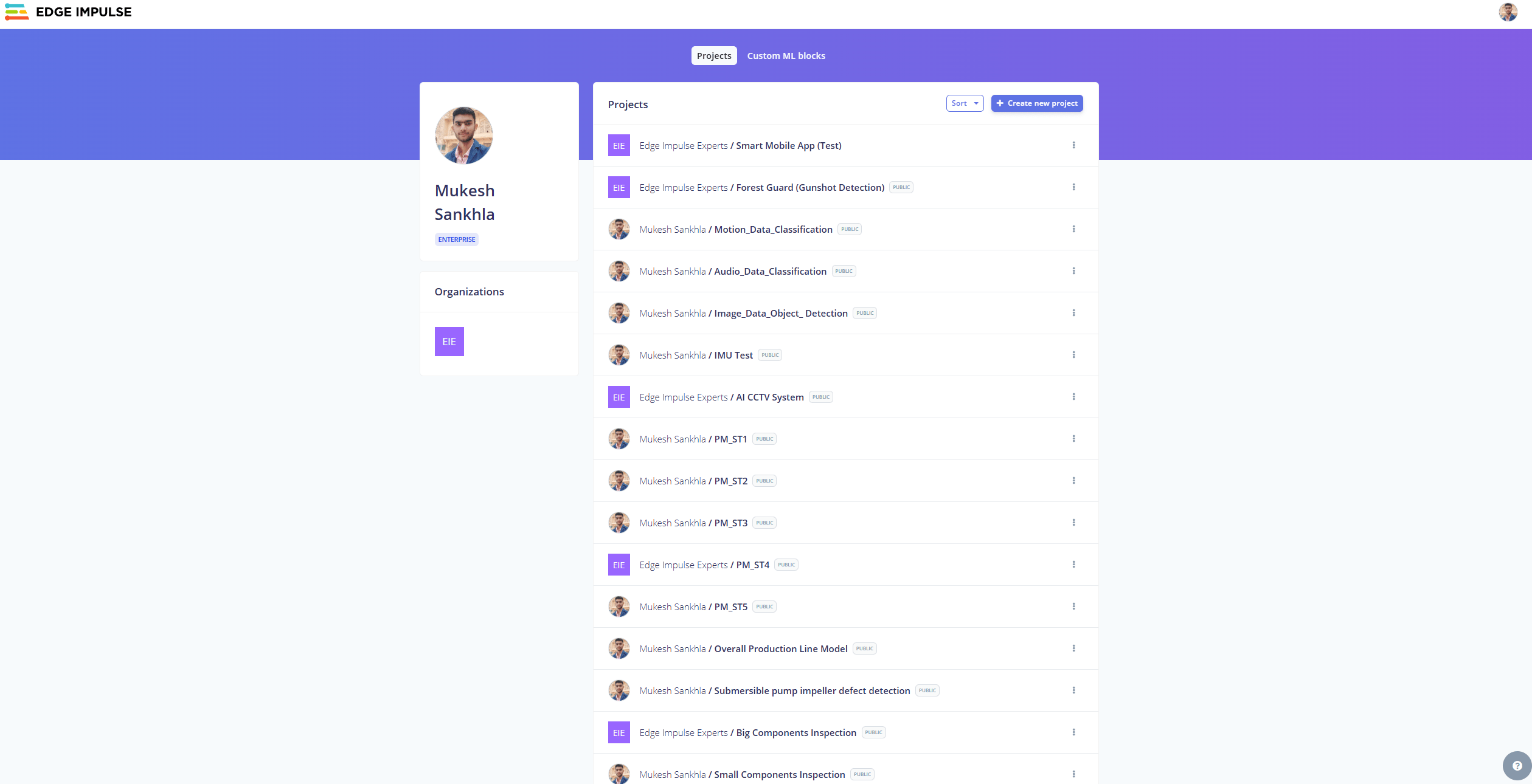
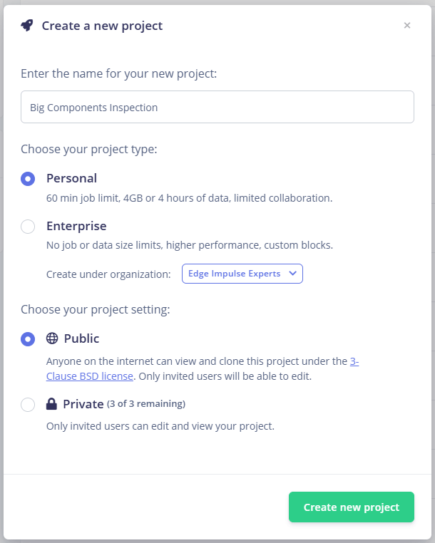 1. Open [Edge Impulse Studio](https://studio.edgeimpulse.com/) and log into your account.
2. Click **Create New Project** and enter a name.
3. In the project dashboard, click **Upload your Model**.
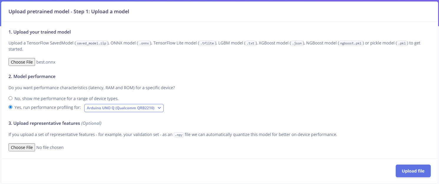
4. Select the `weights/best.onnx` file generated during the YOLO training process.
5. When Edge Impulse asks whether you want performance characteristics (latency, RAM, ROM) for a specific device, select **Yes**.
6. Select **Arduino Uno Q** as the target device.
7. Click **Upload**.
1. Open [Edge Impulse Studio](https://studio.edgeimpulse.com/) and log into your account.
2. Click **Create New Project** and enter a name.
3. In the project dashboard, click **Upload your Model**.
4. Select the `weights/best.onnx` file generated during the YOLO training process.
5. When Edge Impulse asks whether you want performance characteristics (latency, RAM, ROM) for a specific device, select **Yes**.
6. Select **Arduino Uno Q** as the target device.
7. Click **Upload**.
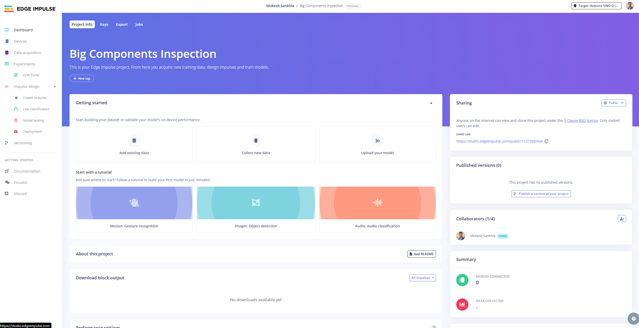
 ### Configuring the Imported Model
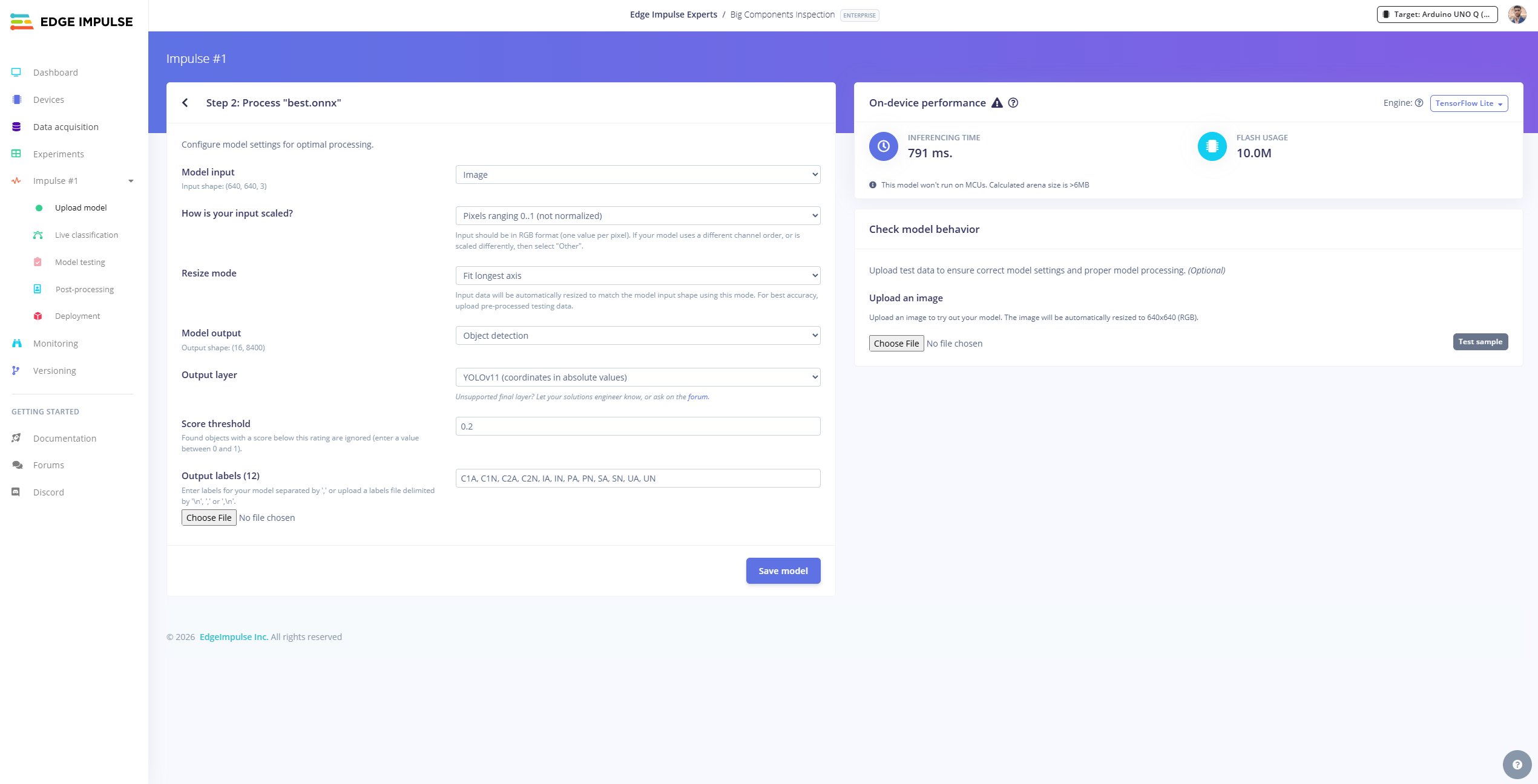 Use the following settings:
* **Model Input:** Image
* **Model Output:** Object Detection
* **Resize Mode:** Fit Long Axis
* **Output Layer:** YOLOv11 (Coordinates in absolute values)
* **Output Labels:** Match the class names used when training the YOLO model.
* Click **Save**.
### Why Use Edge Impulse If We Already Have a YOLO Model?
1. **Customization:** With BYOM, we are not restricted to only models trained inside Edge Impulse. We can train separate YOLO models specifically for slot occupancy, PCB inspection, and PCBA component inspection using standard PyTorch/Ultralytics pipelines.
2. **Performance Optimization:** Edge Impulse profiles and optimizes the model specifically for the target hardware (Qualcomm QRB2210 Linux MPU on the Arduino UNO Q).
3. **Faster Deployment:** Packaging models into standalone `.eim` executable binaries removes external Python runtime overhead and makes deployment seamless.
4. **Flexibility:** Keeps a modular workflow:
$\text{Custom Dataset} \rightarrow \text{YOLO Training} \rightarrow \text{Validation} \rightarrow \text{ONNX} \rightarrow \text{Edge Impulse BYOM} \rightarrow \text{Arduino UNO Q Deployment}$
### Testing and Building the Model
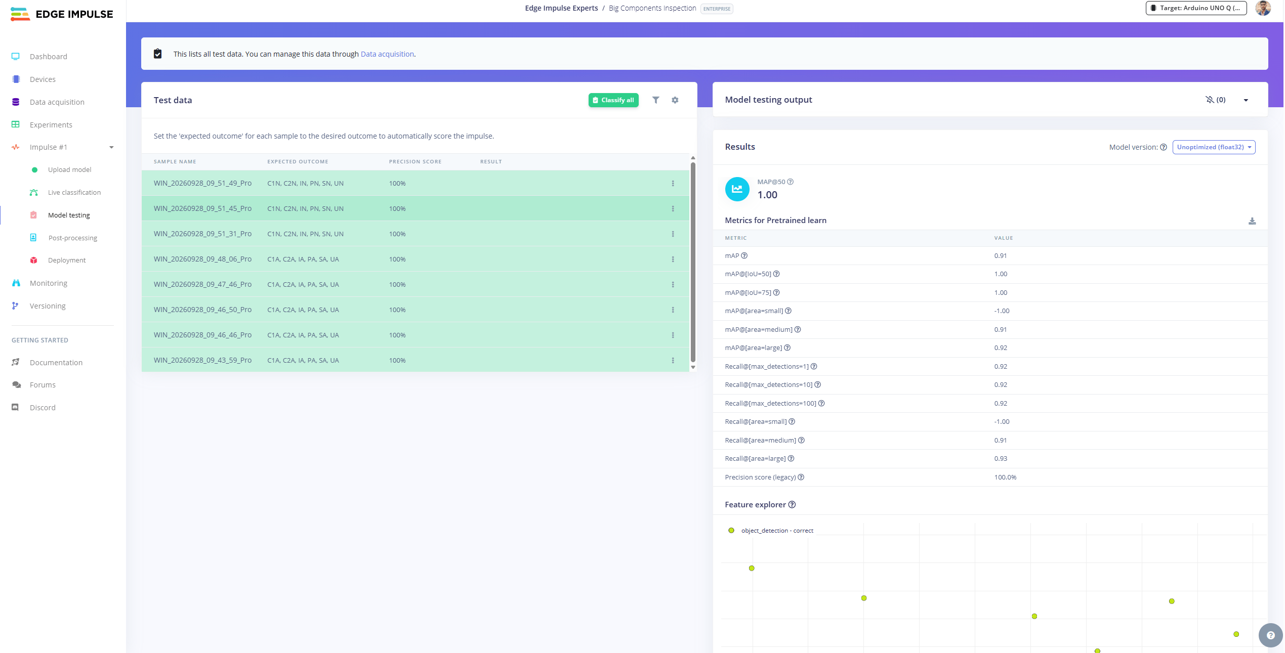
In Edge Impulse, upload validation images to **Data Acquisition**, go to **Model Testing**, and click **Classify All**.
Use the following settings:
* **Model Input:** Image
* **Model Output:** Object Detection
* **Resize Mode:** Fit Long Axis
* **Output Layer:** YOLOv11 (Coordinates in absolute values)
* **Output Labels:** Match the class names used when training the YOLO model.
* Click **Save**.
### Why Use Edge Impulse If We Already Have a YOLO Model?
1. **Customization:** With BYOM, we are not restricted to only models trained inside Edge Impulse. We can train separate YOLO models specifically for slot occupancy, PCB inspection, and PCBA component inspection using standard PyTorch/Ultralytics pipelines.
2. **Performance Optimization:** Edge Impulse profiles and optimizes the model specifically for the target hardware (Qualcomm QRB2210 Linux MPU on the Arduino UNO Q).
3. **Faster Deployment:** Packaging models into standalone `.eim` executable binaries removes external Python runtime overhead and makes deployment seamless.
4. **Flexibility:** Keeps a modular workflow:
$\text{Custom Dataset} \rightarrow \text{YOLO Training} \rightarrow \text{Validation} \rightarrow \text{ONNX} \rightarrow \text{Edge Impulse BYOM} \rightarrow \text{Arduino UNO Q Deployment}$
### Testing and Building the Model
In Edge Impulse, upload validation images to **Data Acquisition**, go to **Model Testing**, and click **Classify All**.
 ## Deploying the Vision Inspection System on Arduino UNO Q
You can also use **Live Classification** directly in the browser to point your webcam at the PCB/PCBA and inspect real-time predictions.
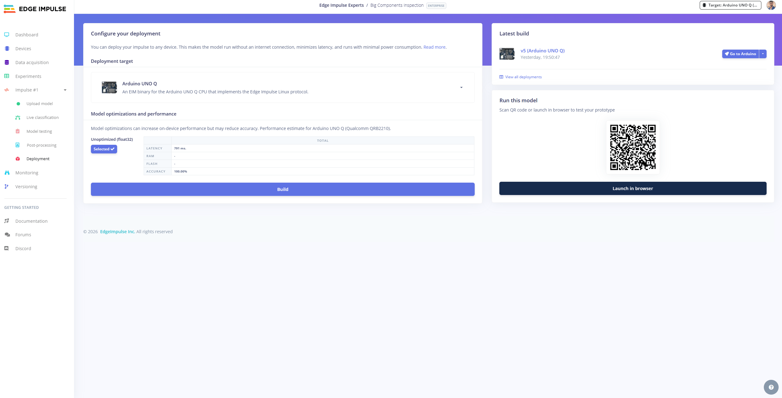
On the **Deployment** page, select **Arduino UNO Q** and click **Build** to download the standalone `.eim` executable binary.
## Deploying the Vision Inspection System on Arduino UNO Q
You can also use **Live Classification** directly in the browser to point your webcam at the PCB/PCBA and inspect real-time predictions.
On the **Deployment** page, select **Arduino UNO Q** and click **Build** to download the standalone `.eim` executable binary.
 With all four `.eim` files ready, we deploy the complete system to the Arduino UNO Q:
```text theme={"system"}
BMS EIM Vision Inspection/
│
├── arduino_firmware/
│ └── bms_servo_led/
│ └── bms_servo_led.ino
│
├── models/
│ ├── slot-occupancy.eim
│ ├── pcb-inspection.eim
│ ├── big-components-inspection.eim
│ └── small-components-inspection.eim
│
├── snapshots/
├── bms_eim_vision_inspection.py
├── requirements.txt
└── README.md
```
With all four `.eim` files ready, we deploy the complete system to the Arduino UNO Q:
```text theme={"system"}
BMS EIM Vision Inspection/
│
├── arduino_firmware/
│ └── bms_servo_led/
│ └── bms_servo_led.ino
│
├── models/
│ ├── slot-occupancy.eim
│ ├── pcb-inspection.eim
│ ├── big-components-inspection.eim
│ └── small-components-inspection.eim
│
├── snapshots/
├── bms_eim_vision_inspection.py
├── requirements.txt
└── README.md
```
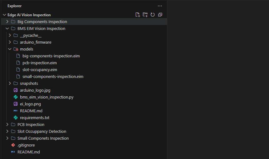 ### Inspection Pipeline Flow
1. **Camera Acquisition:** The webcam continuously captures the inspection area.
2. **Slot Occupancy:** Stage 1 runs `slot-occupancy.eim`.
* If **Empty**: Inspection for this slot is skipped.
* If **PCB**: Runs `pcb-inspection.eim` to check for scratches and defects.
* If **PCBA**: Runs `big-components-inspection.eim` and `small-components-inspection.eim` to verify all components.
3. **PASS / FAIL Logic:** Determines pass/fail status based on missing parts or detected defects.
4. **Hardware Action:** Sends RPC commands to the Arduino firmware to set the WS2812B RGB LED color and rotate the servo turntable to the next slot.
5. **Web Dashboard:** Hosts a live interface on port 5000 to display camera frames, bounding boxes, and pass/fail counts.
```
Camera ──> Slot Occupancy ──> PCB/PCBA Inspection ──> PASS/FAIL ──> RGB LED ──> Rotate to Next Slot
```
### Arduino UNO Q Dual-Domain Architecture (MPU + MCU)
The UNO Q features two separate processors:
* **Qualcomm MPU (Linux):** Runs the Python application, webcam capture, Edge Impulse `.eim` models, inspection logic, and Flask web dashboard.
* **STM32U585 MCU (Zephyr / Arduino):** Handles real-time hardware execution: servo motor PWM on Pin 9 and WS2812B addressable LED data on Pin 8.
Communication uses Arduino's **MessagePack RPC bridge** via a Unix domain socket:
```
Python Application (MPU)
↓
Arduino Router (/var/run/arduino-router.sock)
↓
MessagePack RPC
↓
STM32U585 MCU (Zephyr)
↓
Servo (Pin 9) + WS2812B RGB LED (Pin 8)
```
This clean separation allows the Linux MPU to focus on computer vision and inference, while the MCU handles deterministic real-time hardware timing.
## Step-by-Step Setup & Execution
### Flash Arduino Firmware
### Inspection Pipeline Flow
1. **Camera Acquisition:** The webcam continuously captures the inspection area.
2. **Slot Occupancy:** Stage 1 runs `slot-occupancy.eim`.
* If **Empty**: Inspection for this slot is skipped.
* If **PCB**: Runs `pcb-inspection.eim` to check for scratches and defects.
* If **PCBA**: Runs `big-components-inspection.eim` and `small-components-inspection.eim` to verify all components.
3. **PASS / FAIL Logic:** Determines pass/fail status based on missing parts or detected defects.
4. **Hardware Action:** Sends RPC commands to the Arduino firmware to set the WS2812B RGB LED color and rotate the servo turntable to the next slot.
5. **Web Dashboard:** Hosts a live interface on port 5000 to display camera frames, bounding boxes, and pass/fail counts.
```
Camera ──> Slot Occupancy ──> PCB/PCBA Inspection ──> PASS/FAIL ──> RGB LED ──> Rotate to Next Slot
```
### Arduino UNO Q Dual-Domain Architecture (MPU + MCU)
The UNO Q features two separate processors:
* **Qualcomm MPU (Linux):** Runs the Python application, webcam capture, Edge Impulse `.eim` models, inspection logic, and Flask web dashboard.
* **STM32U585 MCU (Zephyr / Arduino):** Handles real-time hardware execution: servo motor PWM on Pin 9 and WS2812B addressable LED data on Pin 8.
Communication uses Arduino's **MessagePack RPC bridge** via a Unix domain socket:
```
Python Application (MPU)
↓
Arduino Router (/var/run/arduino-router.sock)
↓
MessagePack RPC
↓
STM32U585 MCU (Zephyr)
↓
Servo (Pin 9) + WS2812B RGB LED (Pin 8)
```
This clean separation allows the Linux MPU to focus on computer vision and inference, while the MCU handles deterministic real-time hardware timing.
## Step-by-Step Setup & Execution
### Flash Arduino Firmware
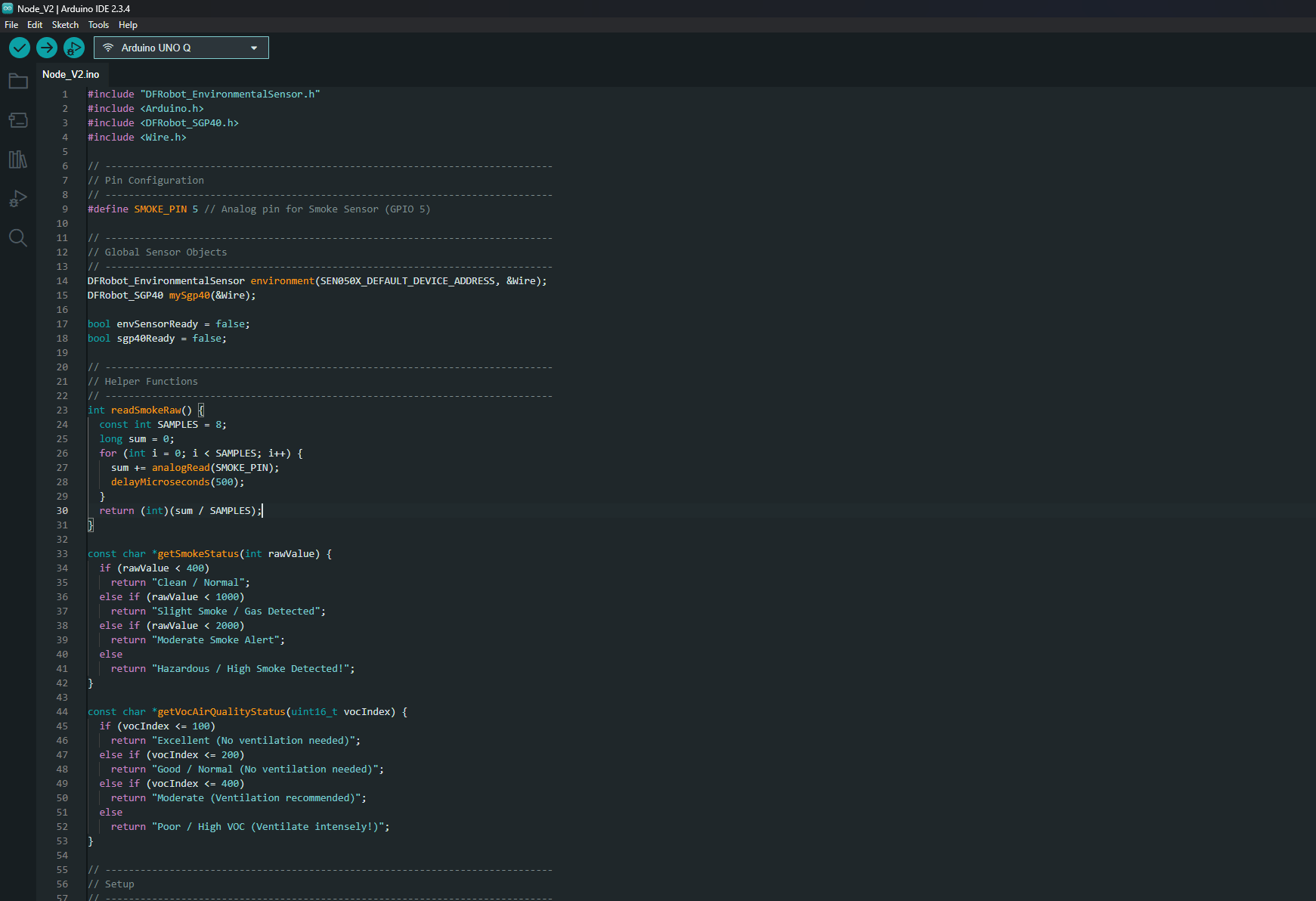 1. Open the Arduino IDE on your computer.
2. Open [`bms_servo_led.ino`](https://github.com/MukeshSankhla/Edge-Ai-Vision-Inspection/blob/main/BMS%20EIM%20Vision%20Inspection/arduino_firmware/bms_servo_led/bms_servo_led.ino) located in:
`BMS EIM Vision Inspection/arduino_firmware/bms_servo_led/bms_servo_led.ino`
3. Select board **Arduino UNO Q** and the corresponding port.
4. Click **Upload**.
5. Once complete, the RGB LED illuminates **green** and the turntable positions itself to **home (0°)**.
### Aligning the Rotating Plate
Check whether the first slot is aligned with the camera. If it is slightly off, loosen the center servo horn screw, manually rotate the plate to exact center, and re-tighten. This sets the mechanical home position.
### Deploying to the Arduino UNO Q
1. Connect the Arduino UNO Q to a powered USB hub and connect the webcam to the same hub.
2. Identify your UNO Q's IP address (e.g., `192.168.1.18`).
3. Copy the project folder to the UNO Q using `scp`:
```bash theme={"system"}
scp -r "BMS EIM Vision Inspection" arduino@192.168.1.18:~/Downloads/
```
4. SSH into the UNO Q:
```bash theme={"system"}
ssh arduino@192.168.1.18
```
5. Set up the Python environment:
```bash theme={"system"}
cd ~/Downloads/"BMS EIM Vision Inspection"
sudo apt update
sudo apt install python3 python3-venv python3-pip -y
python3 -m venv .venv
source .venv/bin/activate
pip install -r requirements.txt
chmod +x models/*.eim
```
6. Start the inspection application:
```bash theme={"system"}
python bms_eim_vision_inspection.py --source 0
```
*(If your webcam is assigned to a different index, try `--source 1` or `--source 2`).*
1. Open the Arduino IDE on your computer.
2. Open [`bms_servo_led.ino`](https://github.com/MukeshSankhla/Edge-Ai-Vision-Inspection/blob/main/BMS%20EIM%20Vision%20Inspection/arduino_firmware/bms_servo_led/bms_servo_led.ino) located in:
`BMS EIM Vision Inspection/arduino_firmware/bms_servo_led/bms_servo_led.ino`
3. Select board **Arduino UNO Q** and the corresponding port.
4. Click **Upload**.
5. Once complete, the RGB LED illuminates **green** and the turntable positions itself to **home (0°)**.
### Aligning the Rotating Plate
Check whether the first slot is aligned with the camera. If it is slightly off, loosen the center servo horn screw, manually rotate the plate to exact center, and re-tighten. This sets the mechanical home position.
### Deploying to the Arduino UNO Q
1. Connect the Arduino UNO Q to a powered USB hub and connect the webcam to the same hub.
2. Identify your UNO Q's IP address (e.g., `192.168.1.18`).
3. Copy the project folder to the UNO Q using `scp`:
```bash theme={"system"}
scp -r "BMS EIM Vision Inspection" arduino@192.168.1.18:~/Downloads/
```
4. SSH into the UNO Q:
```bash theme={"system"}
ssh arduino@192.168.1.18
```
5. Set up the Python environment:
```bash theme={"system"}
cd ~/Downloads/"BMS EIM Vision Inspection"
sudo apt update
sudo apt install python3 python3-venv python3-pip -y
python3 -m venv .venv
source .venv/bin/activate
pip install -r requirements.txt
chmod +x models/*.eim
```
6. Start the inspection application:
```bash theme={"system"}
python bms_eim_vision_inspection.py --source 0
```
*(If your webcam is assigned to a different index, try `--source 1` or `--source 2`).*
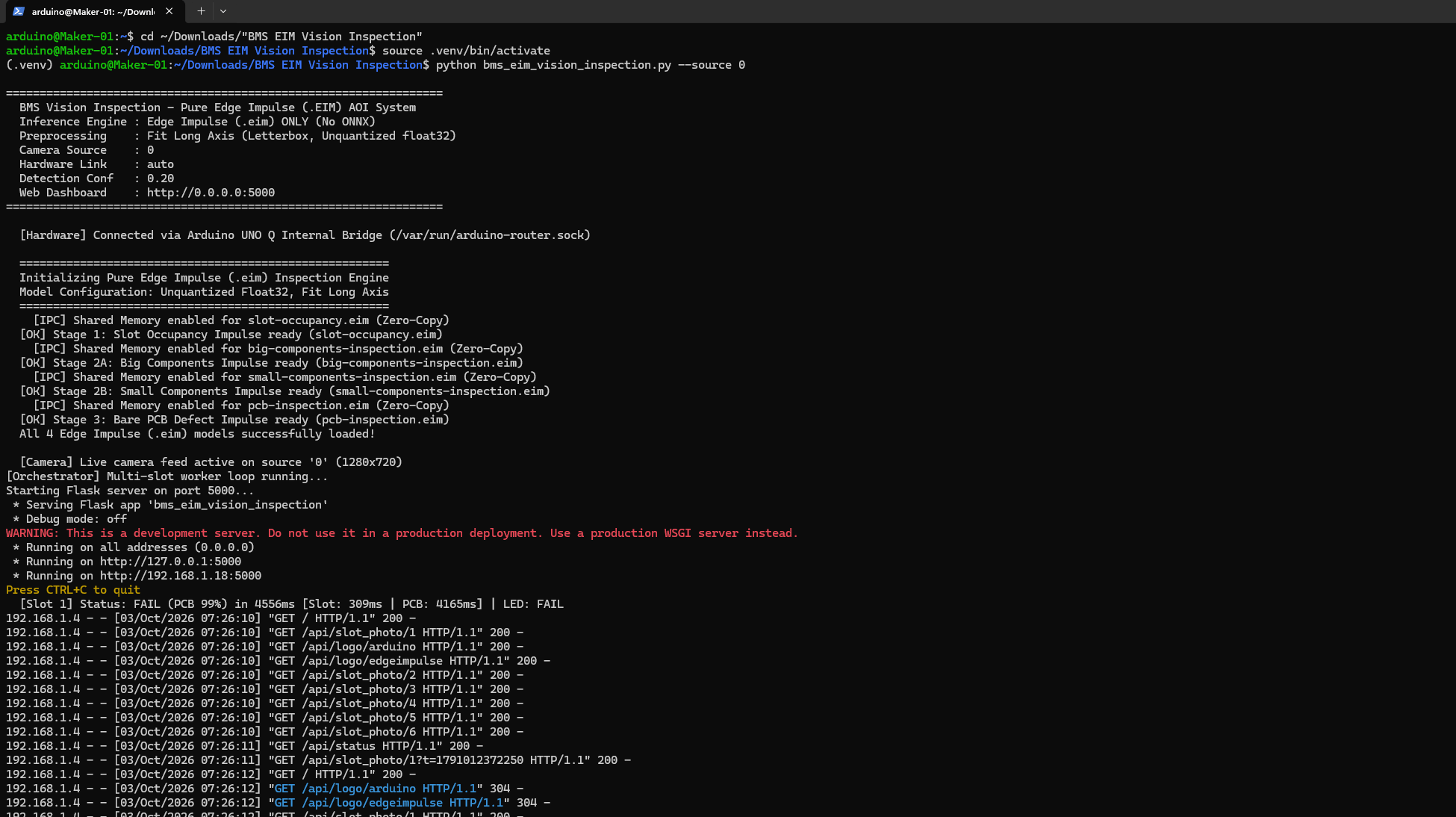 ### Running the Application on Subsequent Boots
```bash theme={"system"}
ssh arduino@192.168.1.18
cd ~/Downloads/"BMS EIM Vision Inspection"
source .venv/bin/activate
python bms_eim_vision_inspection.py --source 0
```
### Accessing the Web Dashboard
Open any browser on the local network and navigate to:
```text theme={"system"}
http://192.168.1.18:5000/
```
### Running the Application on Subsequent Boots
```bash theme={"system"}
ssh arduino@192.168.1.18
cd ~/Downloads/"BMS EIM Vision Inspection"
source .venv/bin/activate
python bms_eim_vision_inspection.py --source 0
```
### Accessing the Web Dashboard
Open any browser on the local network and navigate to:
```text theme={"system"}
http://192.168.1.18:5000/
```
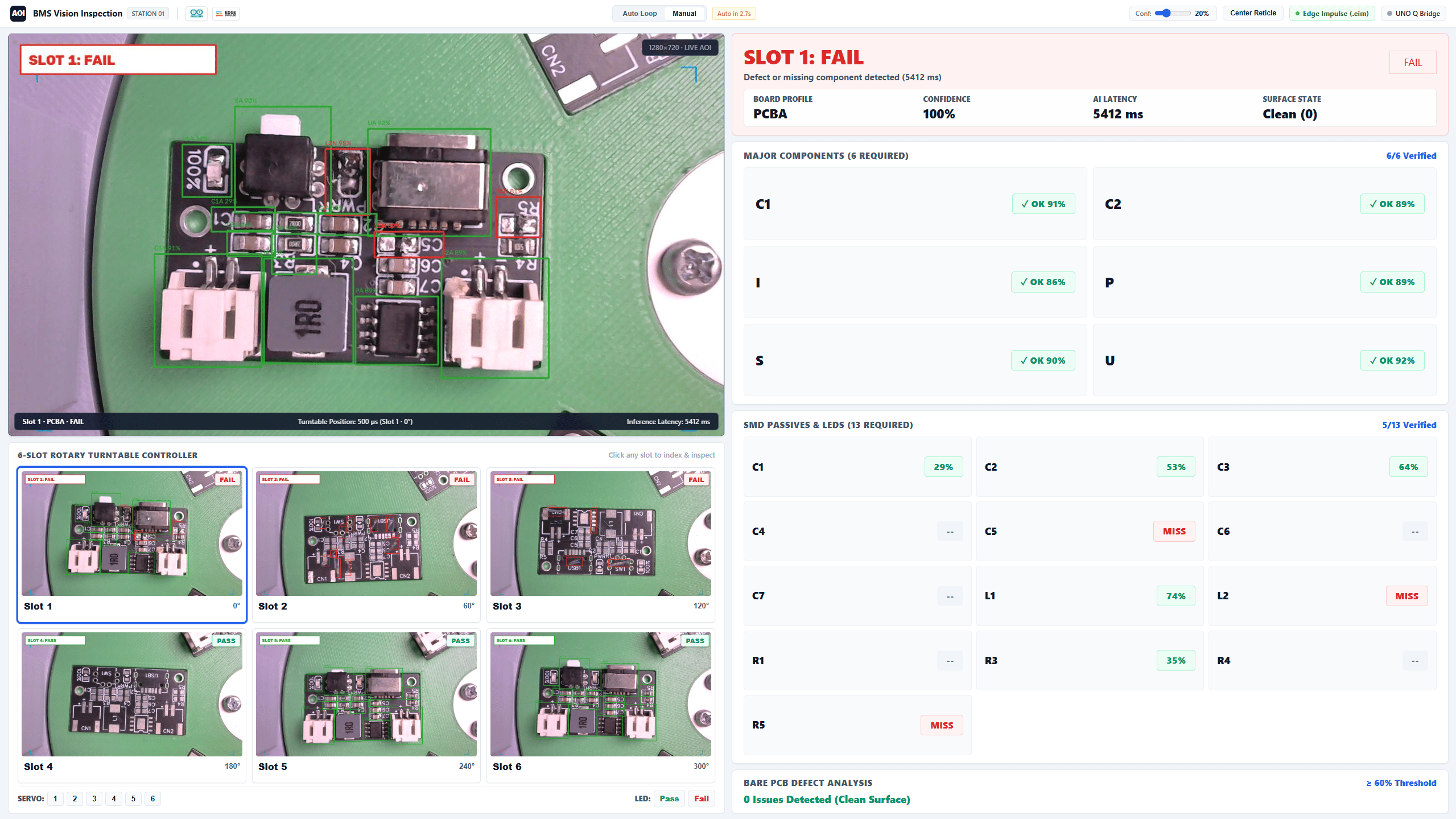
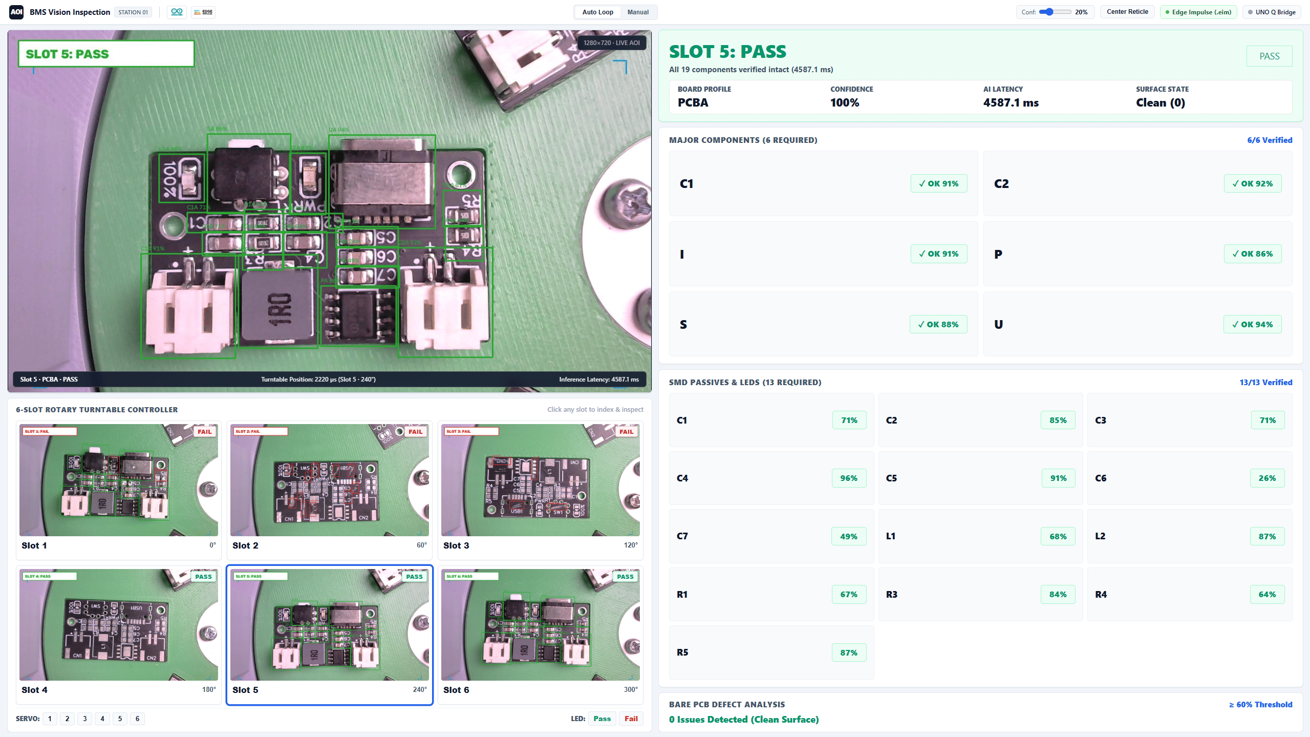
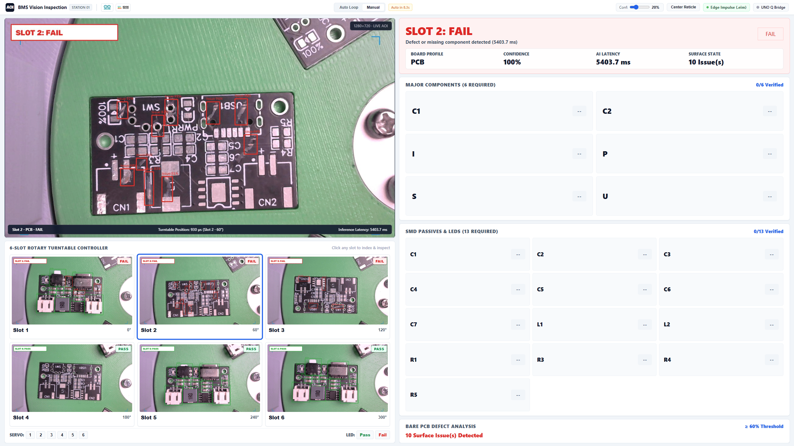
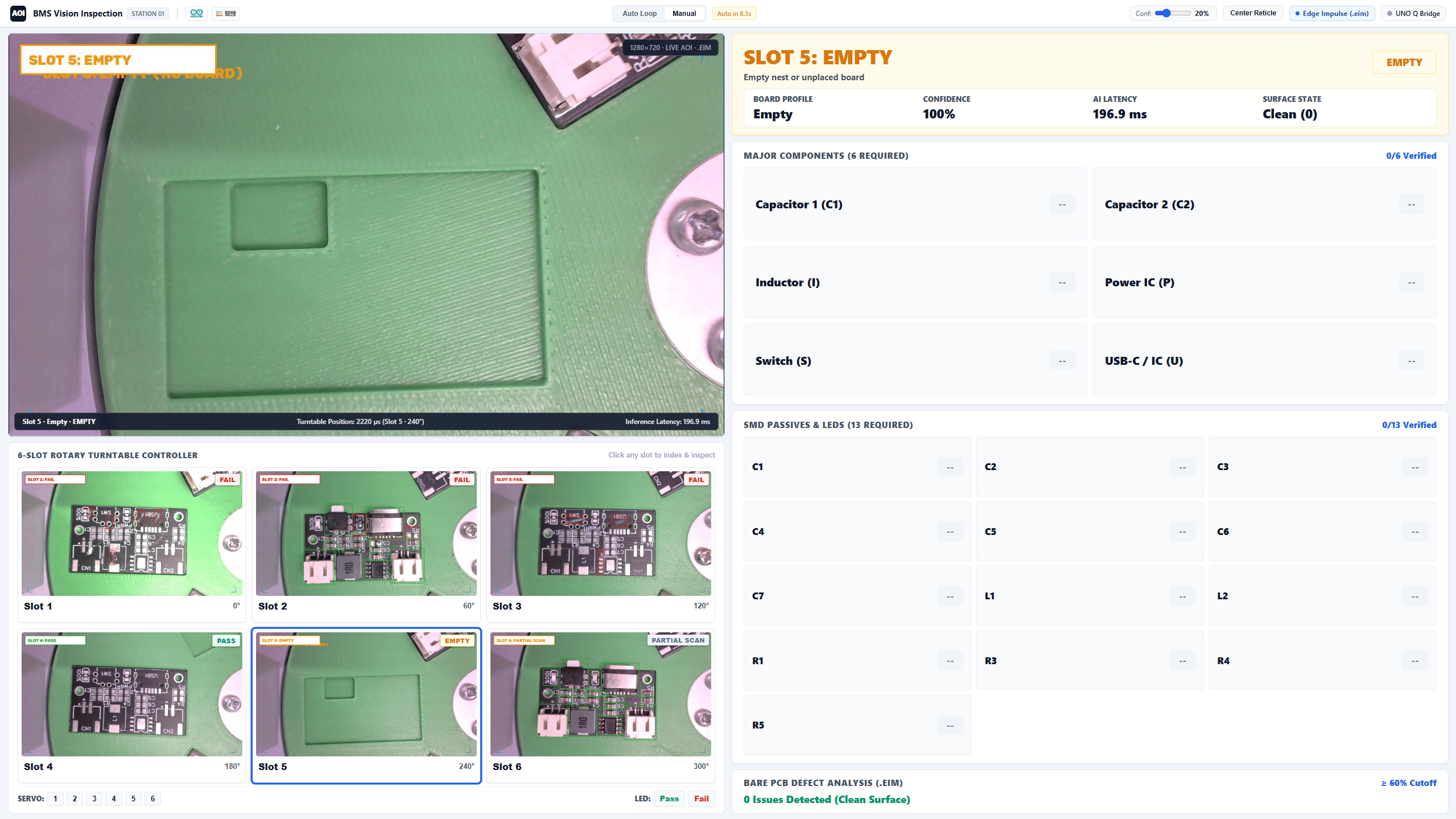 The web dashboard displays:
* Live inspection camera stream with detection overlays
* Current slot number and inspection status (Empty, PCB, PCBA, Pass/Fail)
* Manual turntable indexing and home calibration controls
* Captured defect snapshots and inspection history
## Conclusion
The web dashboard displays:
* Live inspection camera stream with detection overlays
* Current slot number and inspection status (Empty, PCB, PCBA, Pass/Fail)
* Manual turntable indexing and home calibration controls
* Captured defect snapshots and inspection history
## Conclusion
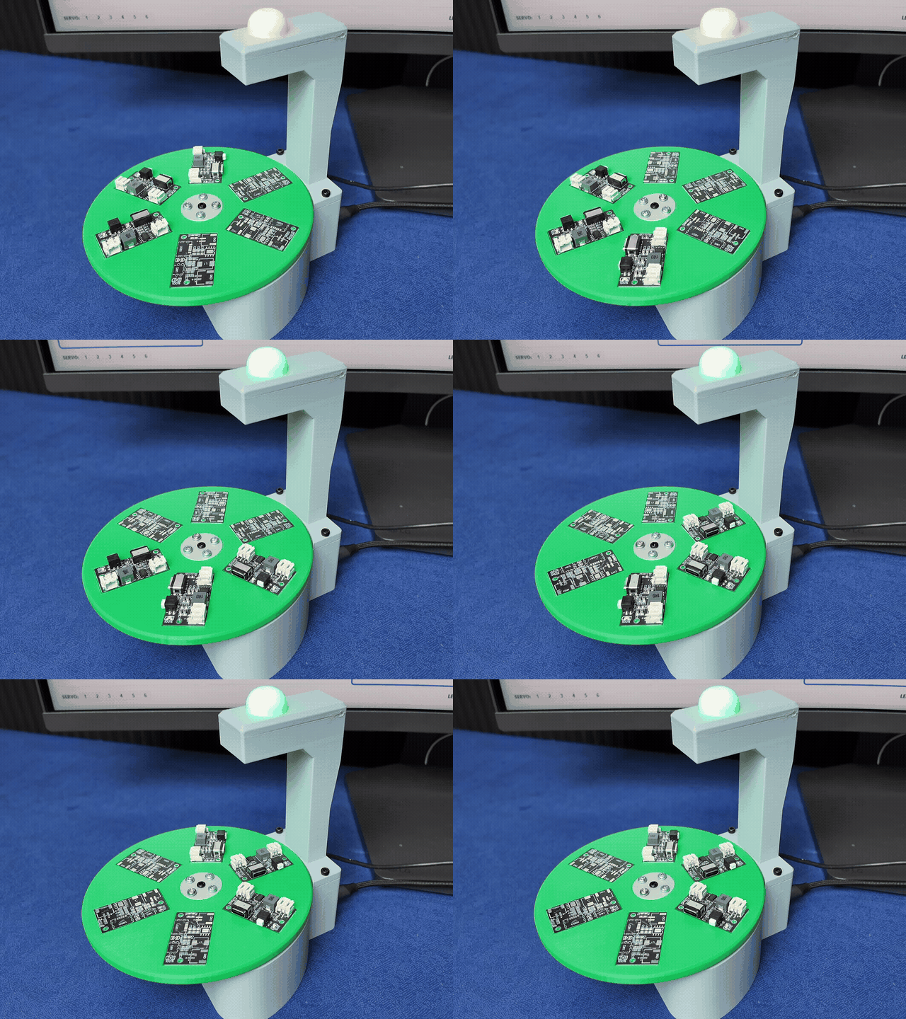 This project demonstrates how edge AI turns low-cost hardware into an industrial-grade vision inspection station. By combining mechanical 3D design, custom YOLO11 models, Edge Impulse BYOM packaging, and the dual-brain Arduino UNO Q, we created a self-contained, real-time AOI (Automated Optical Inspection) system that operates entirely offline without cloud dependencies.
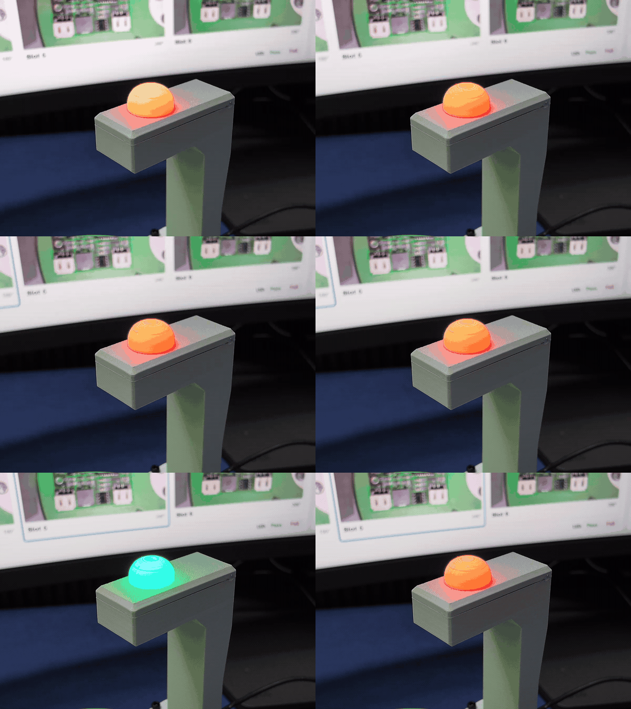 The core workflow:
$\text{Define Inspection} \rightarrow \text{Design Hardware} \rightarrow \text{Collect Data} \rightarrow \text{Train YOLO} \rightarrow \text{Optimize via BYOM} \rightarrow \text{Deploy to UNO Q} \rightarrow \text{Automate}$
This blueprint can be directly adapted for manufacturing quality control, assembly verification, packaging inspection, sorting, and edge robotics.
The core workflow:
$\text{Define Inspection} \rightarrow \text{Design Hardware} \rightarrow \text{Collect Data} \rightarrow \text{Train YOLO} \rightarrow \text{Optimize via BYOM} \rightarrow \text{Deploy to UNO Q} \rightarrow \text{Automate}$
This blueprint can be directly adapted for manufacturing quality control, assembly verification, packaging inspection, sorting, and edge robotics.