> ## Documentation Index
> Fetch the complete documentation index at: https://docs.edgeimpulse.com/llms.txt
> Use this file to discover all available pages before exploring further.
# Cyclist Blind Spot Detection - Himax WE-I Plus
Created By: Adam Taylor, Adam Fry
Public Project Link: [https://studio.edgeimpulse.com/public/108632/latest](https://studio.edgeimpulse.com/public/108632/latest)
 ## Introduction
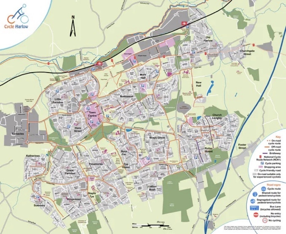
Like many countries, the UK encourages people to cycle, with many cycle paths and cycle-to-work programs. Ideally for safety, the cycle paths are isolated from the main flow of traffic, and my home town of Harlow does pretty well at this.
## Introduction
Like many countries, the UK encourages people to cycle, with many cycle paths and cycle-to-work programs. Ideally for safety, the cycle paths are isolated from the main flow of traffic, and my home town of Harlow does pretty well at this.
 However, Harlow is new town, and as such these paths could be easily planned and built. In the larger cities and older towns such as London, cyclists have to share the road with other users. Sadly each year this leads to fatalities and injuries on the roads, one case which is especially troublesome is when cyclists are on the inside of large vehicles such as trucks, vans, buses etc. When the cyclist is on the inside of the vehicle and the the vehicle is turning left (or right in the most other countries) there exists the conditions for the driver to not see the cyclist and turn into their path. Unfortunately, this leads to many injuries and deaths.
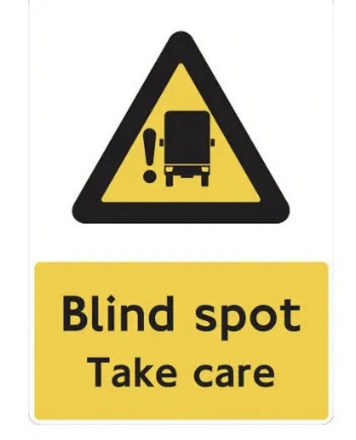
One of the major cause of these incidents is driver visibility. It is difficult for the driver to see down the side of the vehicle. There are attempts to prevent these events, one thing which is used in London on many large vehicles is a warning to Cyclists that they may be in the blind spot of the vehicle.
However, Harlow is new town, and as such these paths could be easily planned and built. In the larger cities and older towns such as London, cyclists have to share the road with other users. Sadly each year this leads to fatalities and injuries on the roads, one case which is especially troublesome is when cyclists are on the inside of large vehicles such as trucks, vans, buses etc. When the cyclist is on the inside of the vehicle and the the vehicle is turning left (or right in the most other countries) there exists the conditions for the driver to not see the cyclist and turn into their path. Unfortunately, this leads to many injuries and deaths.
One of the major cause of these incidents is driver visibility. It is difficult for the driver to see down the side of the vehicle. There are attempts to prevent these events, one thing which is used in London on many large vehicles is a warning to Cyclists that they may be in the blind spot of the vehicle.
 Of course, it would be better for a system which would alert the driver that a cyclist was in their blind spot. This led to me thinking about how it could possibly be achieved, and retrofit into vehicles. Ideally the system would be low cost, small, capable of operating off a battery, and able to give a fast and timely warning to the driver. And, the system needs to be nearly self contained.
My idea was to use a little camera, which would be able to raise an indication or alert to the driver that there was a cyclist in the blind spot. Ideally, this would be audible such that the driver could not fail to see it. For this reason I chose the Himax WE-I Plus camera from SparkFun. This device includes a simple grey-scale VGA camera, and has the ability to break out GPIO such that a buzzer or other warning could be generated.
Of course, it would be better for a system which would alert the driver that a cyclist was in their blind spot. This led to me thinking about how it could possibly be achieved, and retrofit into vehicles. Ideally the system would be low cost, small, capable of operating off a battery, and able to give a fast and timely warning to the driver. And, the system needs to be nearly self contained.
My idea was to use a little camera, which would be able to raise an indication or alert to the driver that there was a cyclist in the blind spot. Ideally, this would be audible such that the driver could not fail to see it. For this reason I chose the Himax WE-I Plus camera from SparkFun. This device includes a simple grey-scale VGA camera, and has the ability to break out GPIO such that a buzzer or other warning could be generated.
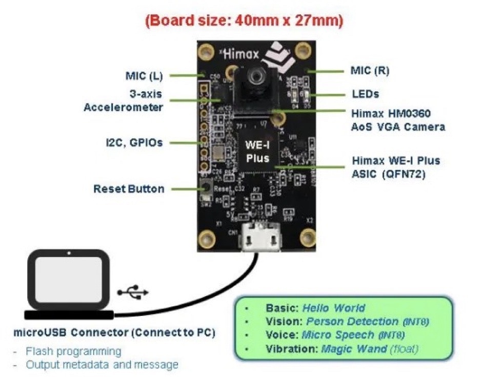 The USB connector can be used for powering the device, and it is small enough to be easily packaged and deployed.
The best way to be able to detect cyclists is to capture an image and analyse if a Cyclist is present. This is a perfect job for machine learning, specifically object detection. As we want to deploy at the edge on a small, power-constrained microprocessor, it is an ideal use case for Edge Impulse and their Faster Objects, More Objects (FOMO) algorithm.
## What is FOMO
Image classification, where we say if an item is present in a image, works well as long as there is only a single object in the image.
Alternatively, object detection is able to provide the class, number of objects and positions in the image. This is what we need for cyclist detection as real world conditions mean there will be many objects in the image and there may be several cyclists also in the same image. It is crucial when this occurs we do detect the cyclist, for this reason we need a object detection algorithm.
However, object detection algorithms are very computationally intensive and therefore struggle to be as responsive as necessary for this use case on a microcontroller.
This is where the FOMO algorithm developed by Edge Impulse comes into play, it provides a simplified version of object detection.
## Dataset
Like with all ML/AI projects, one of the largest challenges is in collecting a dataset. There is not a large, publicly available, dataset so we started to collect a small dataset to enable training and proof of concept. If the concept works we can create a larger dataset which addresses more conditions such as low light, weather, etc.
The initial dataset used consisted of 100 images of cyclists in different conditions tagged from around the world. These images were collected from open source images available across the web.
Once the dataset is collected we are able to create the Edge Impulse project.
## Edge Impulse Project
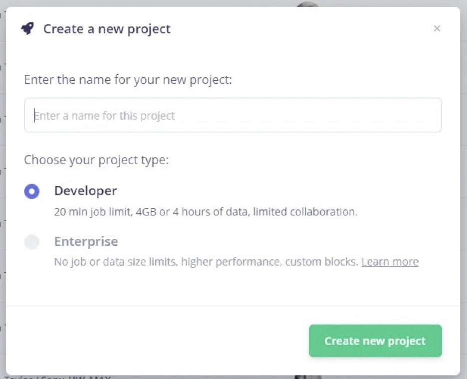
The first thing do is log into your [Edge Impulse account](https://www.edgeimpulse.com) and create a new project.
The USB connector can be used for powering the device, and it is small enough to be easily packaged and deployed.
The best way to be able to detect cyclists is to capture an image and analyse if a Cyclist is present. This is a perfect job for machine learning, specifically object detection. As we want to deploy at the edge on a small, power-constrained microprocessor, it is an ideal use case for Edge Impulse and their Faster Objects, More Objects (FOMO) algorithm.
## What is FOMO
Image classification, where we say if an item is present in a image, works well as long as there is only a single object in the image.
Alternatively, object detection is able to provide the class, number of objects and positions in the image. This is what we need for cyclist detection as real world conditions mean there will be many objects in the image and there may be several cyclists also in the same image. It is crucial when this occurs we do detect the cyclist, for this reason we need a object detection algorithm.
However, object detection algorithms are very computationally intensive and therefore struggle to be as responsive as necessary for this use case on a microcontroller.
This is where the FOMO algorithm developed by Edge Impulse comes into play, it provides a simplified version of object detection.
## Dataset
Like with all ML/AI projects, one of the largest challenges is in collecting a dataset. There is not a large, publicly available, dataset so we started to collect a small dataset to enable training and proof of concept. If the concept works we can create a larger dataset which addresses more conditions such as low light, weather, etc.
The initial dataset used consisted of 100 images of cyclists in different conditions tagged from around the world. These images were collected from open source images available across the web.
Once the dataset is collected we are able to create the Edge Impulse project.
## Edge Impulse Project
The first thing do is log into your [Edge Impulse account](https://www.edgeimpulse.com) and create a new project.
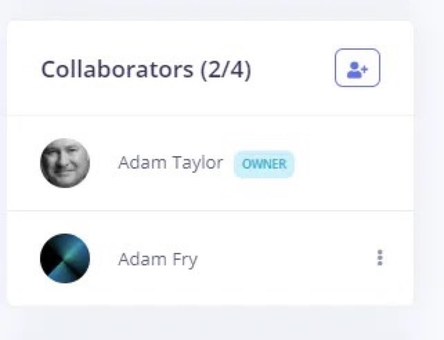
 Once the project is created we need to get started working on it. I had a work experience student with me this week from the local high school. He helped me create the dataset and train the model, we were able to work collaboratively on the project due to Edge Impulse's new collaboration feature.
On the project Dashboard, select "Add collaborator" and in the dialog add in either the username or email of the individual.
Once the project is created we need to get started working on it. I had a work experience student with me this week from the local high school. He helped me create the dataset and train the model, we were able to work collaboratively on the project due to Edge Impulse's new collaboration feature.
On the project Dashboard, select "Add collaborator" and in the dialog add in either the username or email of the individual.
 Once they are added you can then easily work together on the project. This enabled Adam F. to work on uploading and labelling the dataset, while I attended meetings.
 Each of the images is uploaded and labeled with the location of the Cyclist.
As you upload the images you will notice the labeling queue in the data acquisition page displays the number of items to be labeled.
Each of the images is uploaded and labeled with the location of the Cyclist.
As you upload the images you will notice the labeling queue in the data acquisition page displays the number of items to be labeled.
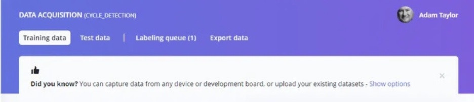 By clicking on the labelling queue you can label each image.
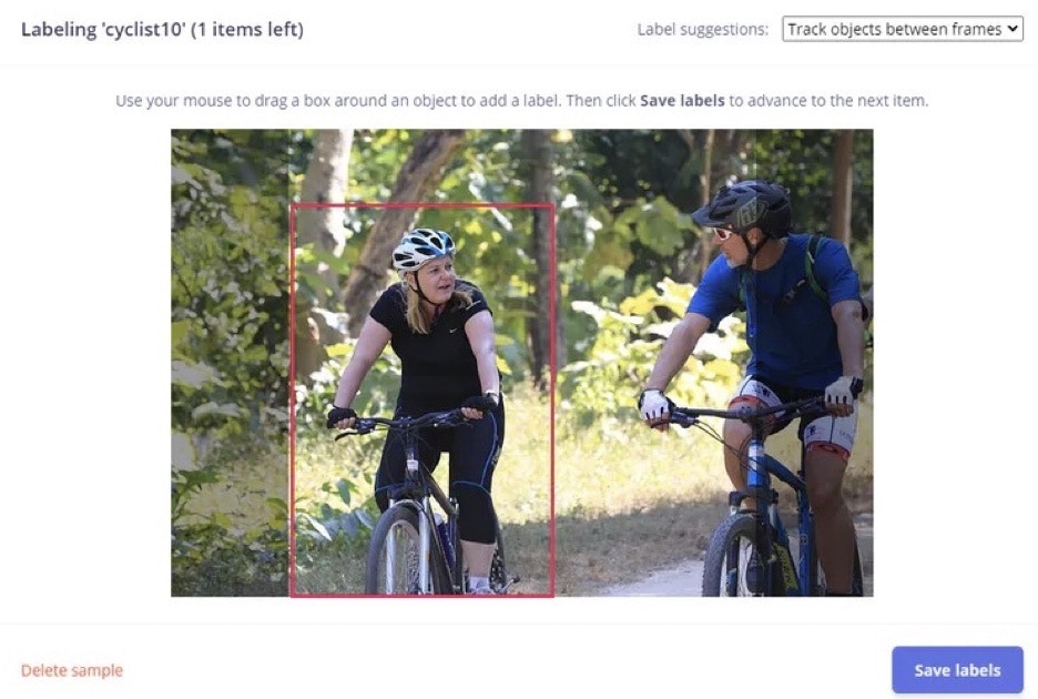 Once the bounding box is drawn around the object, the next step is to enter the label.
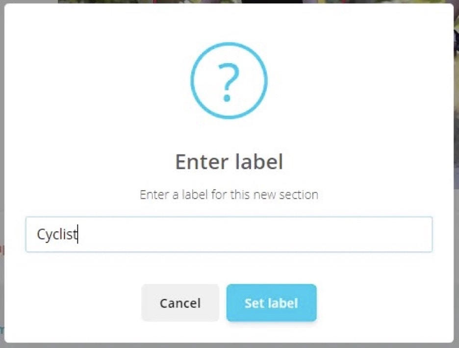 Using this view we can work through each of the images which needs to be labeled.
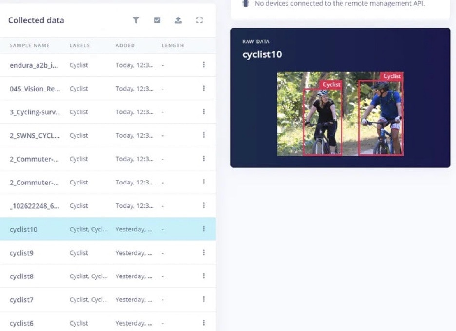 The next step with the data labeled is to create the impulse.
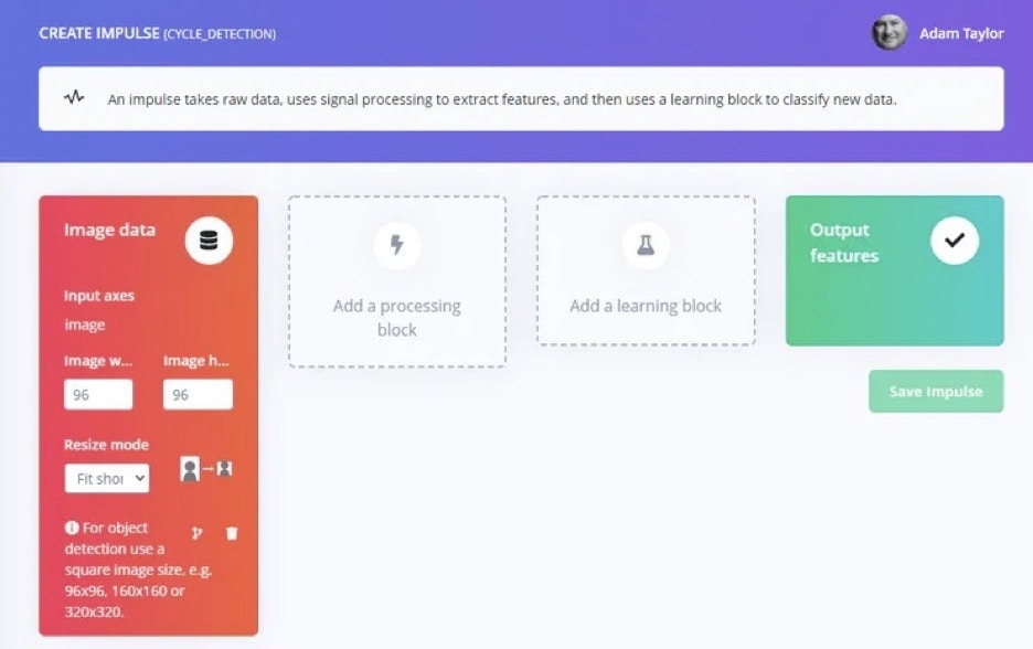 The first step is to add a processing block - Select "Image Processing" block.
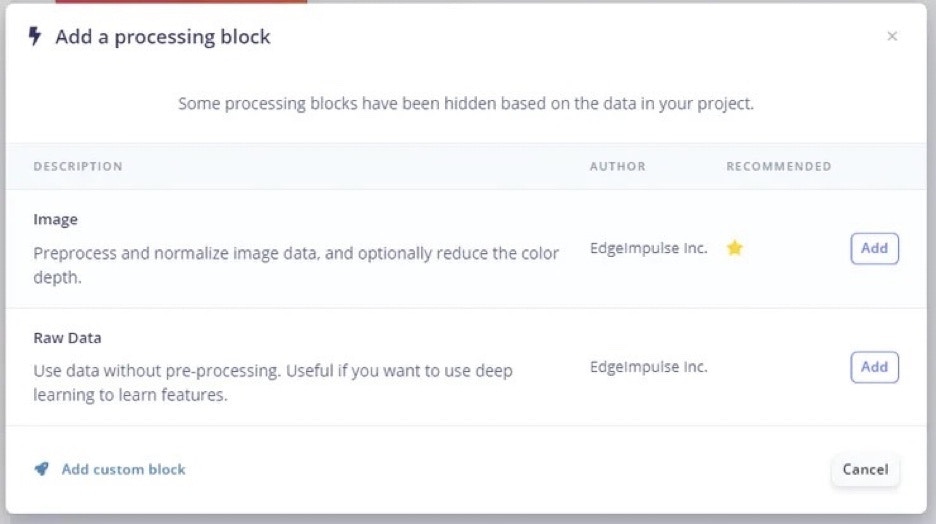 Then we can add the processing block.
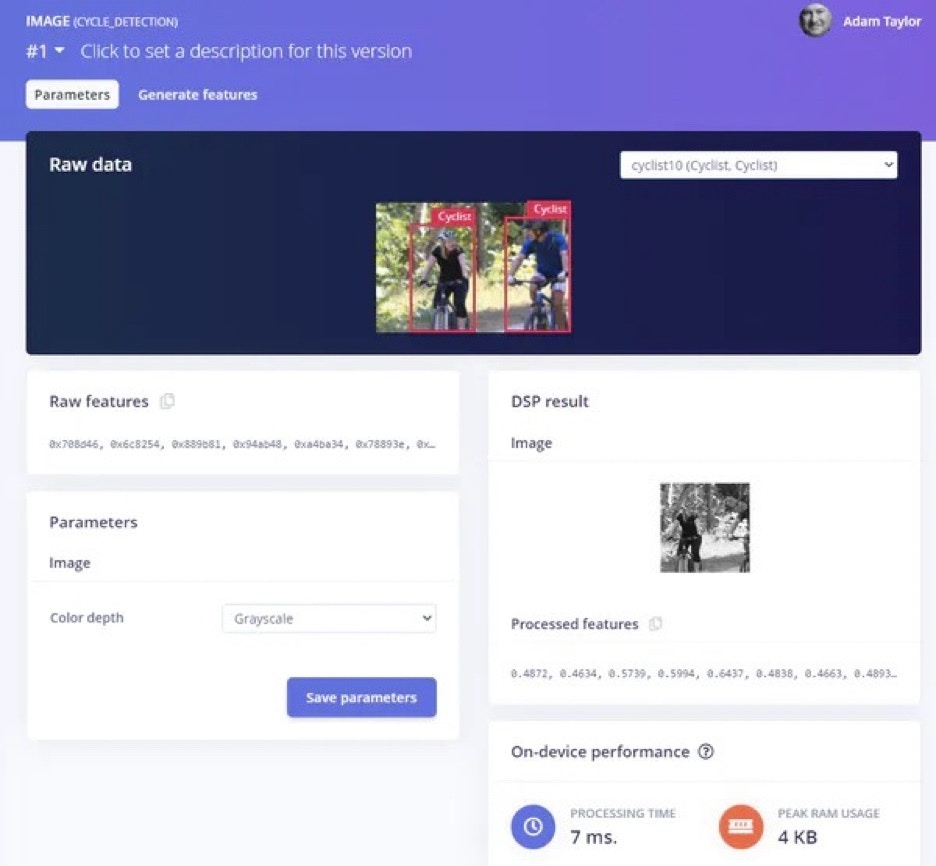
 With the impulse created the next stage is to configure the image processing block. Change the color depth to Black and White.
 Select the "Generate Features" tab and click "Generate features".
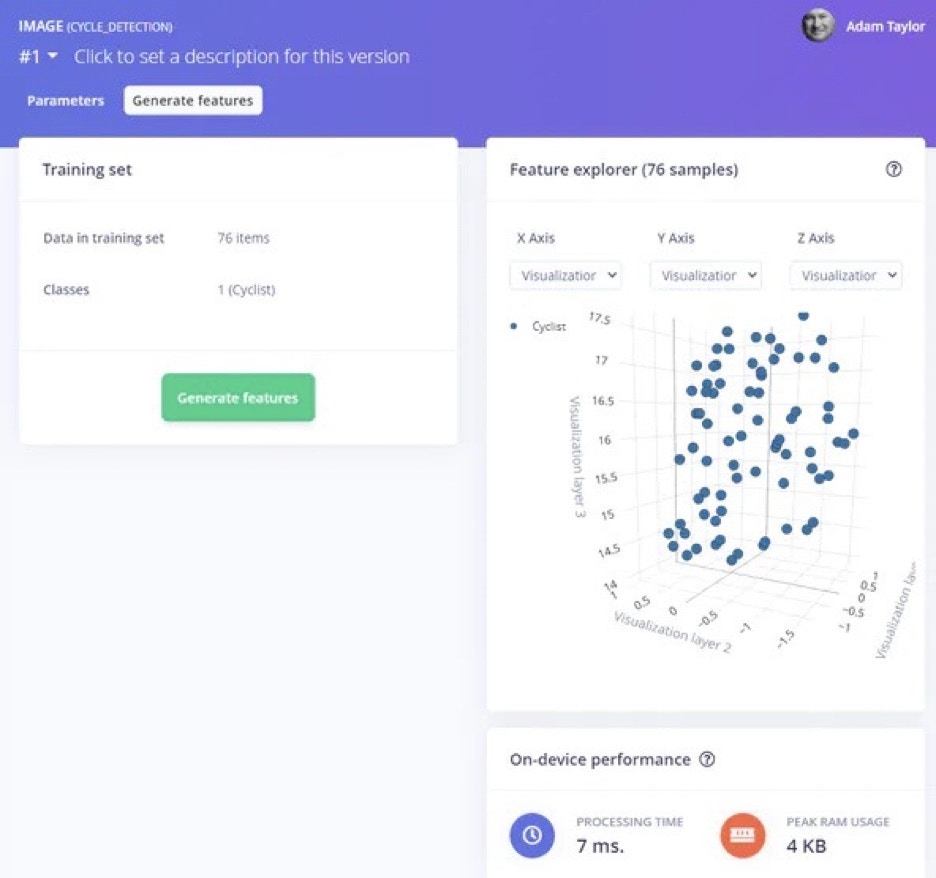 These are the features which will be taken forward for training in the processing block.
The final stage is to train the model.
These are the features which will be taken forward for training in the processing block.
The final stage is to train the model.
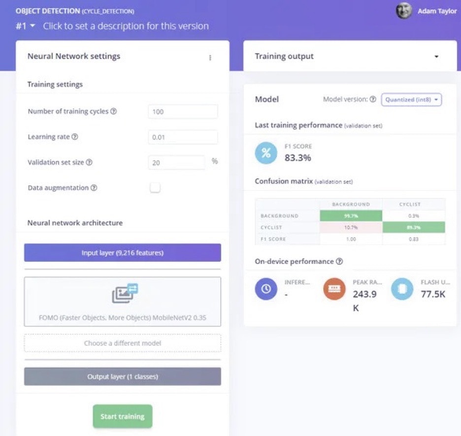
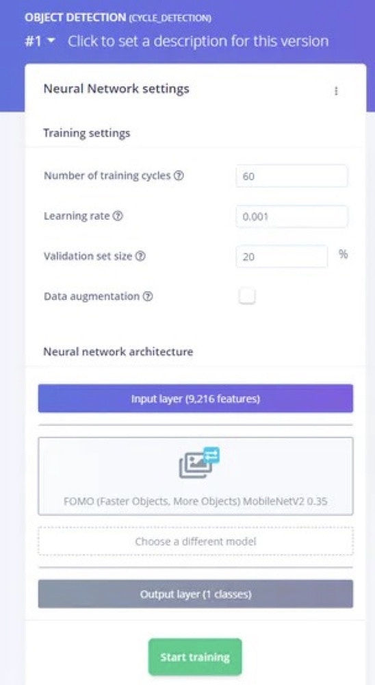 Once the model is trained we will see a confusion matrix which shows the performance. The initial training was good but the F1 score (which is the a key indication of the result) was too low.
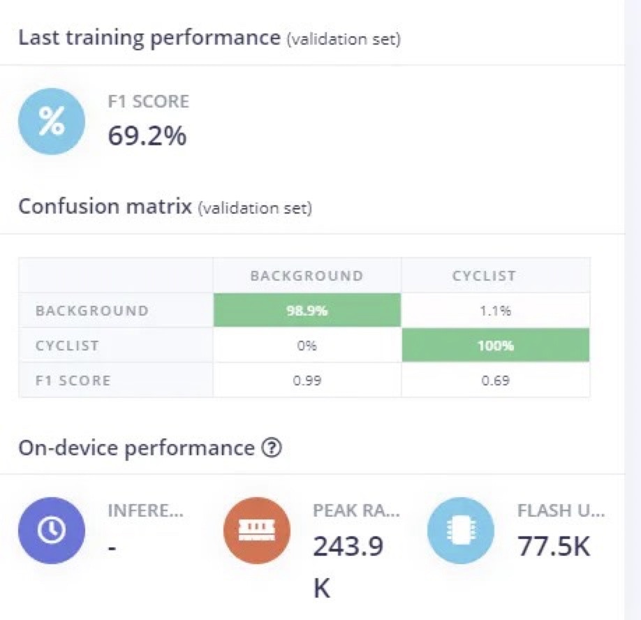 While it looks good on individual images like below.
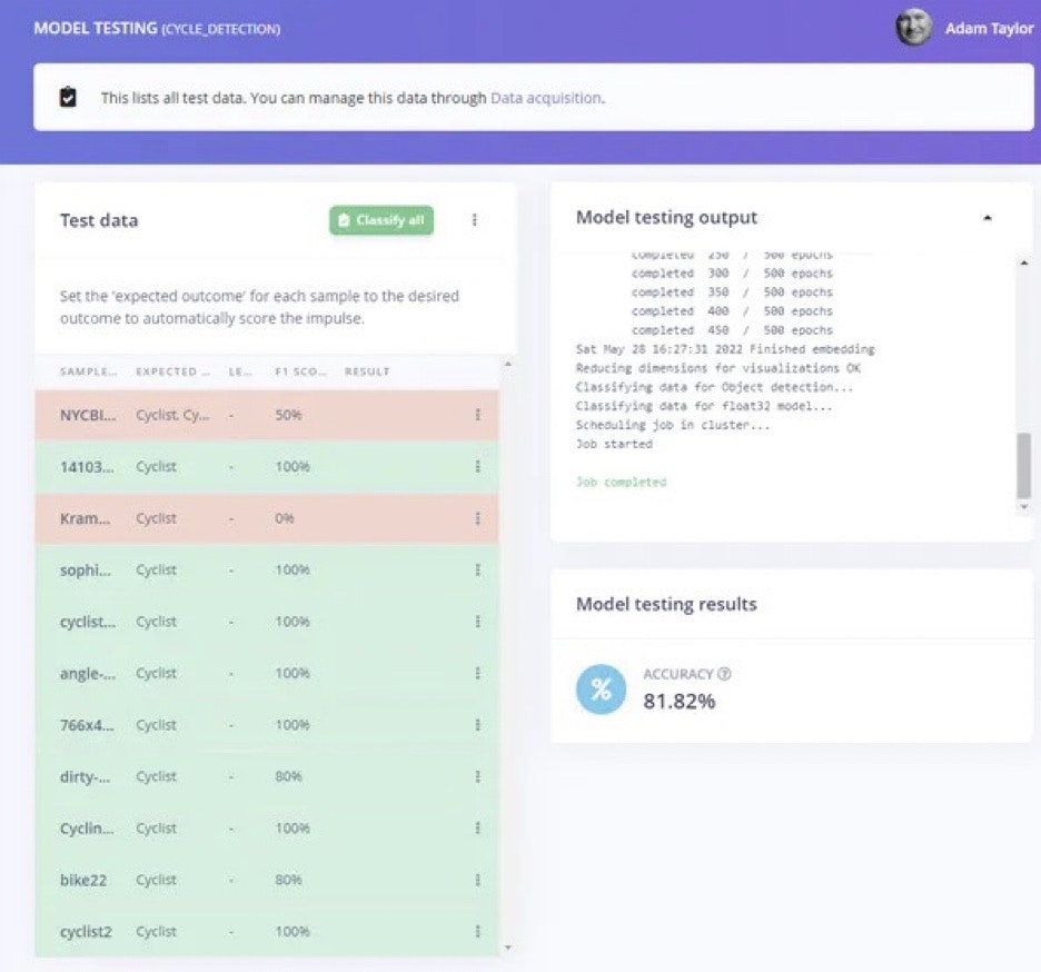
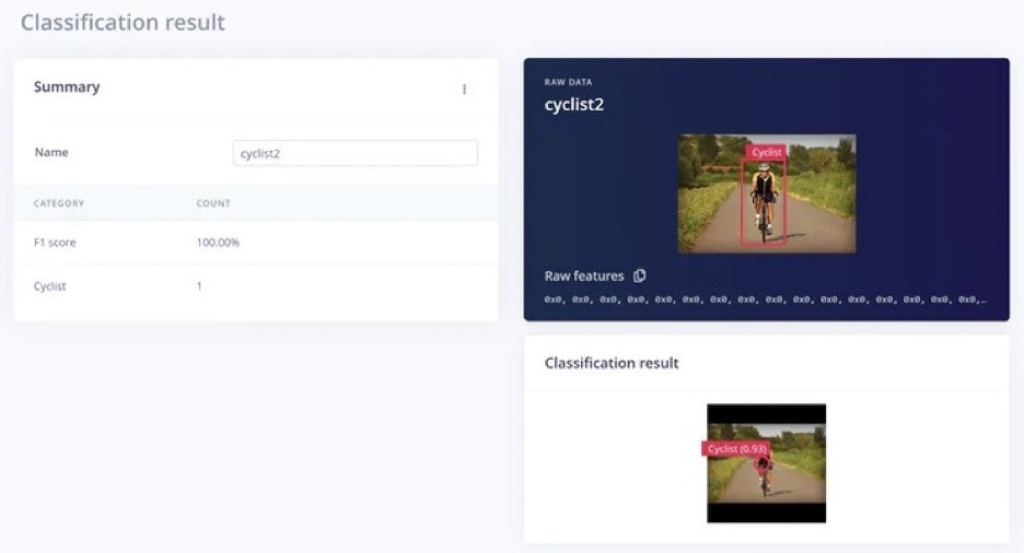 When we test it on the entire validation set the accuracy score was very low, only 36%, which is not acceptable.
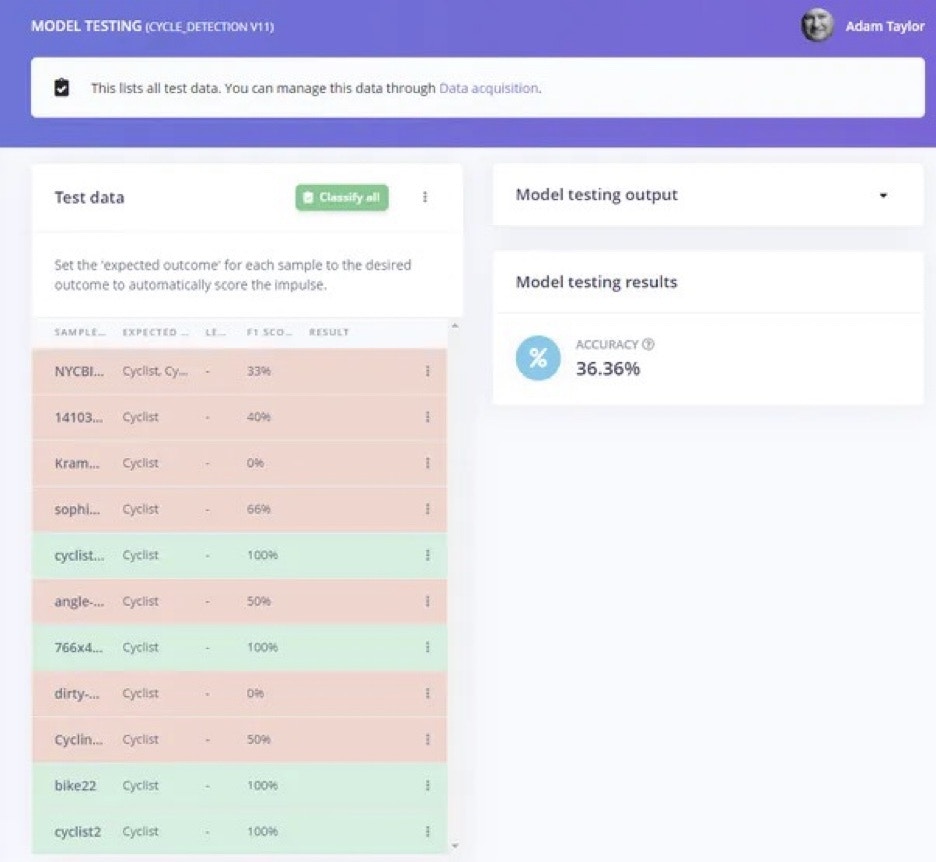 We can get better performance than this. However, before we change the settings of the project, we will save a version of it. This will allow us to save the current state of the project, so we have a version we can revert to if necessary.
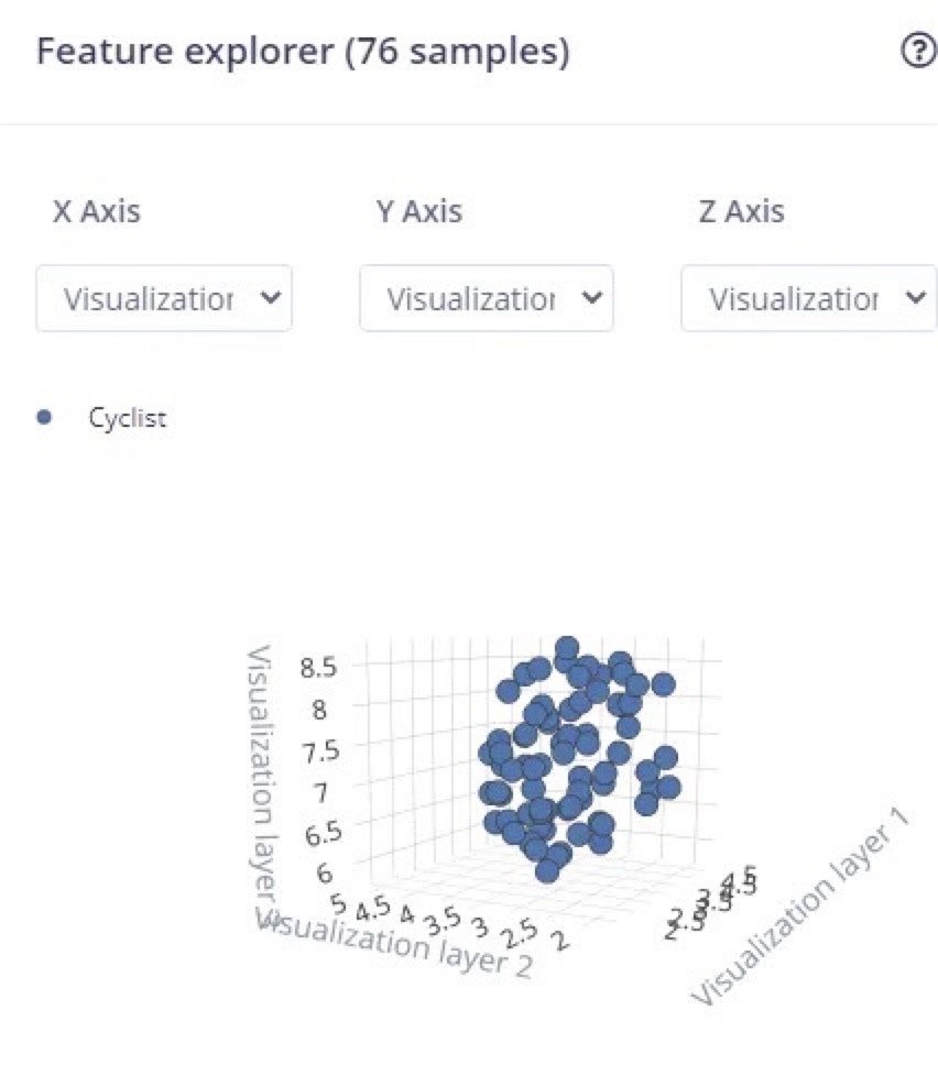
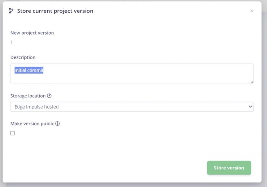 With the version saved, the next step is to change some of the project settings. Investigating the project settings, the generated features are not closely clustered.
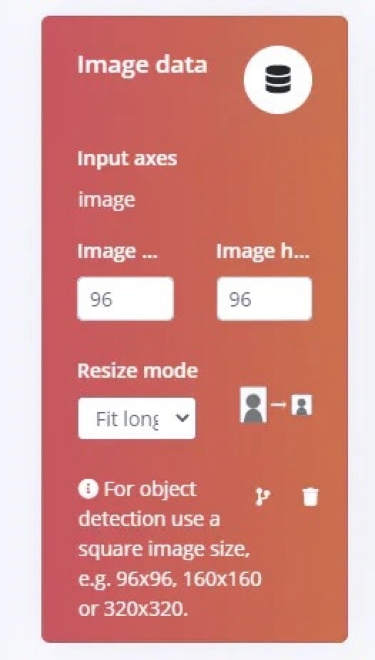
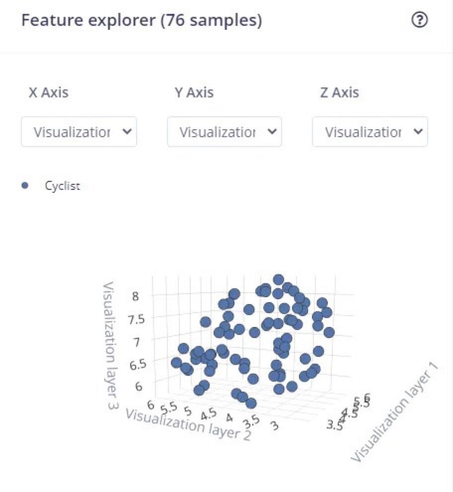 We can change the setting on the resize, to resize with respect to the longest side.
 Regenerating the features shows a much closer clustering in the Feature Explorer.
 I also changed the number of training cycles, and the learning rate. This resulted in a better F1 score, though a slightly reduced accuracy compared to previously.
 This resulted in much better performance when tested against the validation set.
 To deploy the algorithm on the target hardware we select "Deploy" and choose the Himax WE-i Plus camera from the options.
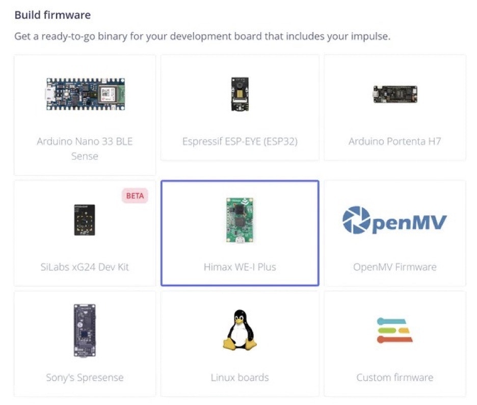 This will generate an application directly for the target device.
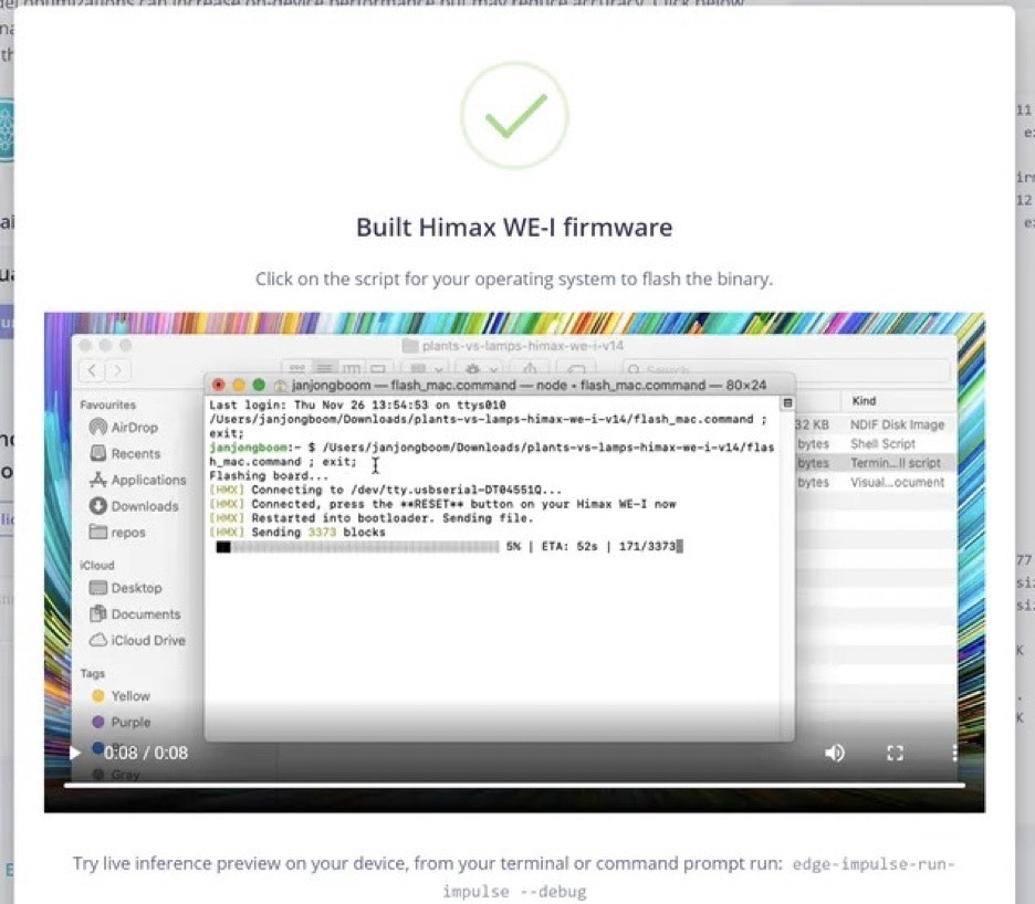 To load the application onto the Himax WE-I Plus, extract the downloaded folder and run the batch file for your operating system, then follow the on-screen commands.
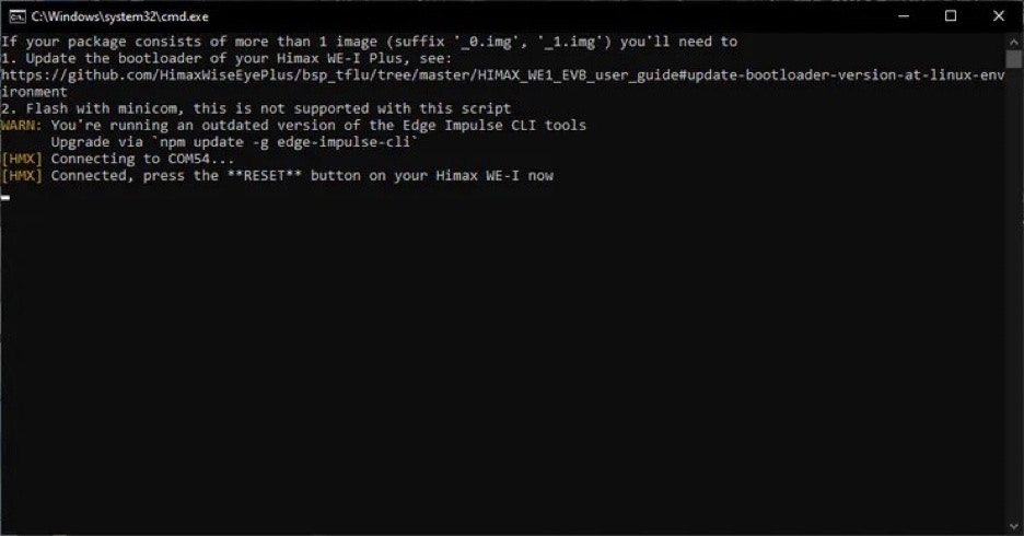 Press the Reset button on the device when instructed.
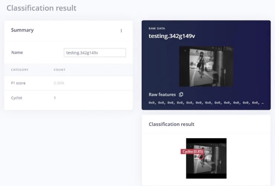
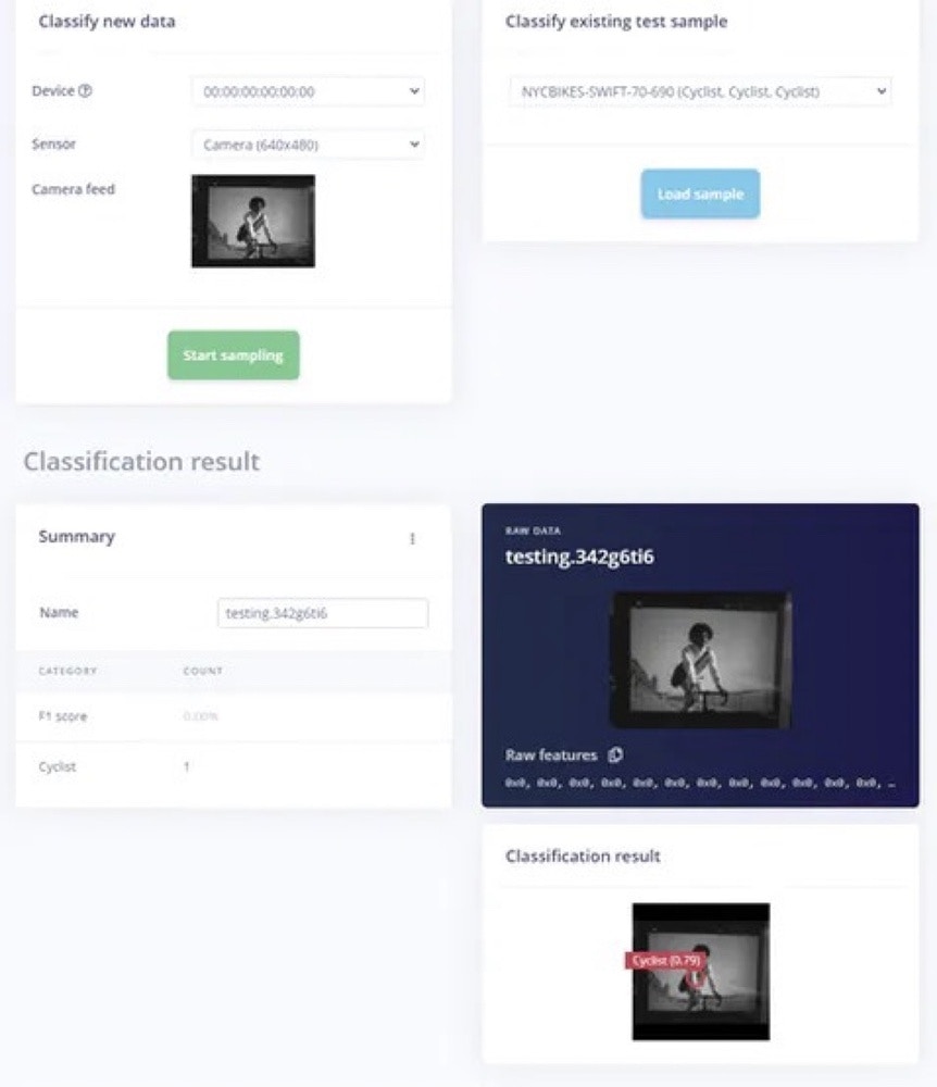
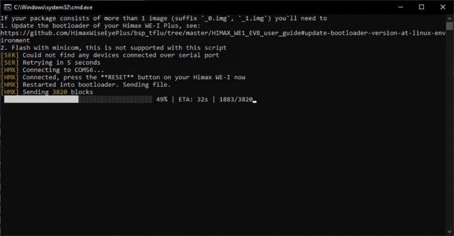 With the application flashed, we are able to run some tests using the camera against images, using live Classification.
Both images were correctly identified as a cyclists.
With the application flashed, we are able to run some tests using the camera against images, using live Classification.
Both images were correctly identified as a cyclists.
 Second classification:
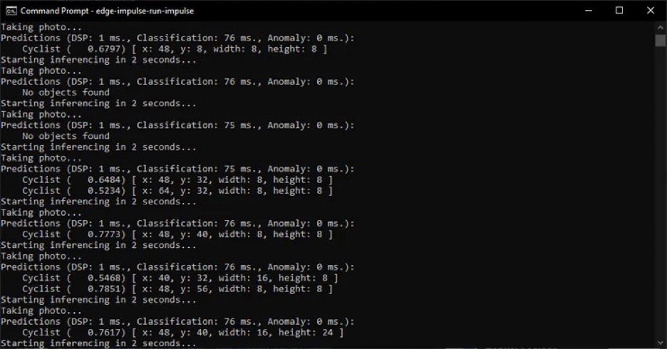
 The final step is run the application on the board, standalone. Testing this against a range of images shows cyclists detected.
 ## Wrap Up
This project shows that tinyML can be used in a small microcontroller-based image processing system to detect cyclists. This approach can be further developed to produce a system which can be used to increase road safety.
## Wrap Up
This project shows that tinyML can be used in a small microcontroller-based image processing system to detect cyclists. This approach can be further developed to produce a system which can be used to increase road safety.